www.arpnjournals.com
A CIRCULARLY POLARIZED APERTURE-COUPLED PATCH ELEMENT
FOR FLAT LENS ANTENNAS
Abdisamad A. Awaleh and Samsul H. Dahlan
Research Centre for Applied Electromagnetics, Faculty of Electrical and Electronics Engineering, Universiti Tun Hussein Onn Malaysia (UTHM), 86400 Parit Raja, Batu Pahat, Johor, Malaysia
E-Mail: [email protected], [email protected]
ABSTRACT
A circularly polarized flat lens antenna element is presented in this article. The element is designed by using aperture-coupled patches with a common ground plane. A pair of identical cross-shaped slots is loaded on the common ground plane to realize circular polarization (CP). The desired phase error compensation and axial ratio performance for CP are achieved by tuning the slots dimensions. The proposed element achieves a very good 3 dB axial ratio bandwidth of 21%, phase shift range of 225° and low transmission coefficient of only 1.9 dB.This element employs a simple and less fabrication complexity mechanism for polarization conversion.
Key words: Array Lens Circular Polarization Aperture-Coupled Cross-shaped Slot
INTRODUCTION
Circularly polarized antennas are required in modern wireless communications systems such as space communications. Flat lens antenna has potential benefits and effective antenna solutions for airborne application (Thornton and Huang, 2012). It has a high gain, light weight and low-cost compared to the bulky and high cost conventional dielectric lenses (Godi et al., 2007).A feed antenna usually horn or Microstip patch is used to illuminate one side of the array lens to create a space-fed antenna system as shown in Figure 1(a) (Thornton and Huang, 2012). The subject attracted significant interest for the last decade and researchers widely studied the performance improvement and less manufacturing complexity of this antenna (Awaleh and Dahlan, 2014), (Ryan et al., 2010), (Kaouach et al., 2009). High performance linearly polarized flat lens antennas based on different phase controlling techniques are reported in literature (Pozar, 1996), (Awaleh and Dahlan, 2014), (Padilla et al., 2010).
However, realization of circularly polarized flat lens antenna array has been a challenging task. Most of the design efforts for circularly polarized lens planar array use element patch rotation to generate two orthogonal field components (Phillion and Okoniewski, 2011), (Kaouach et al., 2011). Furthermore, using metallic vias to connect the element patches or the cascaded antenna layers have some manufacturing complexities.
The aim of this paper is to design a circularly polarized element by using simple and compact structure for planar lens antenna array. Two cross-shaped slots loaded on the common ground plane were used to achieve the desired axial ratio performance and phase error compensation. The effect of several parameters for the element operation and performance were examined. Details about unit cell design configurations and analysis are presented in the second section, followed by parametric studies and discussion of results in third and fourth sections respectively. Finally, the conclusion of the work is given in the last section.
PROPOSED UNIT CELL DESIGN
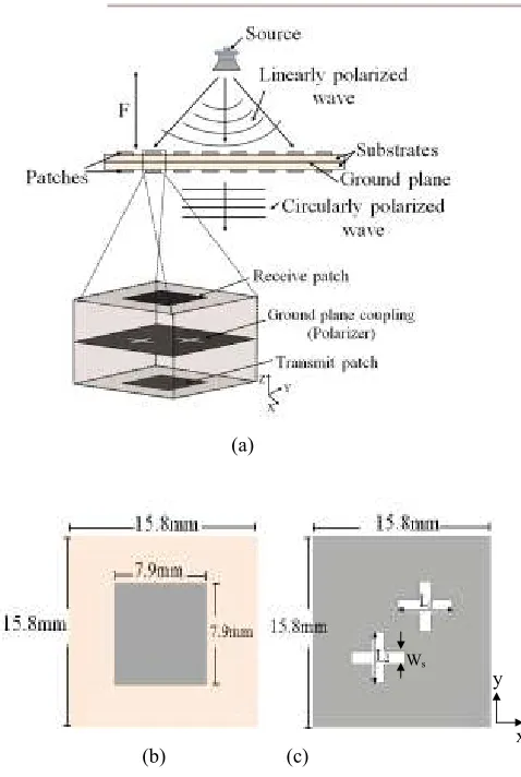
The geometry of the proposed aperture-coupled element for circularly polarized flat lens antenna is shown in Figure 1. The unit cell structure consists of two back-to-back square patches with non-resonating aperture-coupled common ground plane. Two identical cross-shaped apertures are diagonally placed at the center of the common ground plane. The element dimensions are organized in a square pattern, where the unit cell size equals 15.8×15.8 mm2 (λ°/2×λ°/2 at 9.5 GHz). Two square patches of size 7.9×7.9 mm2 are printed on two standard FR4 substrates having relative permittivity (εr) of 4.3, dielectric loss tangent (tan δ) of 0.02 and physical thickness of 1.6 mm.
(a)
[image:2.612.71.310.66.422.2](b) (c)
Figure 1: Geometry of the proposed unit cell (a) Flat lens antenna and unit cell illustrations (b) square patch (c) Slotted
common ground plane.
The linearly polarized incident wave that impinges on the receiving surface of the element has two orthogonal electric field modes (Eix and Eiy) with constant magnitude and phase. The signal is coupled through the cross-shaped apertures (polarizer) to achieve a circularly polarized radiated wave. Figure 2 illustrates waveguide simulator model where the unit cell boundary condition is properly defined to create an infinite array lens behavior. The magnitude of the transmission coefficients radiated by the element are represented as Tx and Ty for x and y polarization components respectively.
The antenna unit cells have been simulated and analyzed by using the commercially available CST Microwave Studio software. A linearly polarized incident wave oriented at 45° along the x-axis (see Figure 2) and travelling into the negative z-direction was fed into the unit cell. The incident wave can be expressed as the superposition of the transverse electric (TE) and transverse magnetic (TM) modes. Therefore, in order to obtain circularly polarized (CP) radiated modes, a common technique is to excite two orthogonal linearly polarized field components with a constant magnitude and a 90° phase difference.
To realize this polarization conversion technique, the incident field components can be decomposed into two orthogonal modes, in which one E field component is perpendicular to the receiving patch of the unit cell while the other is parallel to the patch. However, as the signal passes through the cross-shaped coupling apertures; the mode with E field parallel to the patch tends to be delayed more than the other component. Thus, due to the delaying effect, the two modes will be 90° out of phase. Hence, creates a circularly polarized mode at the back of the aperture.
Figure 2: Unit cell boundary condition setup showing the incident wave angle and field
components.
As mentioned, the outgoing wave has two orthogonal modes which have the same amplitude, but 90° out of phase. Therefore, by considering the circular polarization requirements, the scattering transmission parameters of the outgoing wave can be expressed as
|S21,x| = |S21,y| (1)
∆Φ = ∠S21,x - ∠S21,y (2)
where ∆Φ is the differential phase of the components.
The radiated circularly polarized wave may be referred to as right-handed circular polarization (RHCP) or left-handed circular polarization (LHCP), depending on the rotation of the electric and magnetic field vectors. For instance, the wave will be indicated by RHCP if the TM mode is reflected with 90° (±360°) phase advanced with respect to the TE component and LHCP if the TE mode is reflected with 90° (±360°) phase advance with respect to the TM component (Sohail et al., 2013). The unit cell |S21,x| and |S21,y| transmission coefficients are shown in Figure 3. Notice that they achieve equal amplitude at the design frequency (9.5 GHz).
Ws
y
[image:2.612.351.544.203.387.2]Figure 3: Predicted transmission coefficients for x and y polarizations
RESULTS AND DISCUSSION
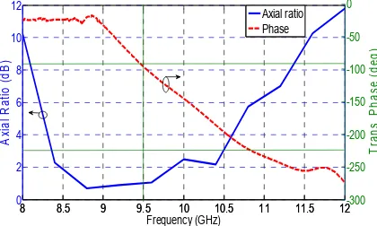
In order to realize the circular polarization of the unit cell, systematic variations of slots dimensions are carried out. The cross-shaped apertures have dimensions of L1, L2 and Ws in which the slot length (L1) controls the amount of coupling or contributes the phase shift performance of the element, while the second slot length (L2) and slot width (Ws) have much lesser effect as explained in Section IV. As shown in Figure 3 in Section II, the element excites two orthogonal modes with an equal transmission magnitude at the design frequency (9.5 GHz). Figure 4 also illustrates the phase difference (-90°) between the two orthogonal components with a wideband axial ratio performance. The designed element uses simple technique to produce circular polarization with a reflection coefficient of better than -10 dB, transmission coefficient of around 1.9 dB (see Figure 5), phase shift range of 225° and axial ratio of less than 3 dB.
Figure 4: Axial ratio performance of the element and phase difference between the two orthogonal modes.
Figure 5: S-parameters of the element (L1 = L2 = 4.5 mm, Ws = 1.5 mm)
PARAMETRIC STUDIES
This unit cell design has several adjustable parameters that need to be studied. This provides further comprehension on the unit cell functionality and performance. Therefore, careful parametric optimizations improve the element performance and exhibit the potential benefits of using this element design in flat lens antenna for airborne application. The unit cell parametric studies have been carried out using the electromagnetic simulation software CST microwave Studio.
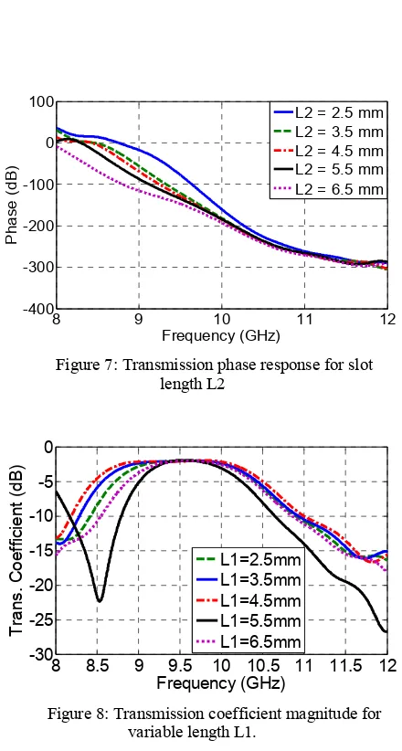
[image:3.612.332.542.119.252.2]The effect of the cross slots lengths (L1 and L2) on unit cell s-parameters and axial ratio performance are thoroughly examined. The lengths are varied from 2.5 mm to 6.5 mm while the slots width (Ws) is kept constant as it shows lesser effect on s-parameters performances. Figure 6 shows the transmission phase response of the slot length L1 while the slot length L2 variation result is shown in Figure 7. It can be seen from Figure 6 that varying the aperture length L1 achieves a distribution phase range of 225° with transmission magnitude of better than -1.9 dB (see Figure 8). It is also found that tuning slot length L2 demonstrates a very small phase change effect as illustrated in Figure 7.
Figure 6: Transmission phase performance for slot length L1
8.5 9 9.5 10 10.5 11 11.5
[image:3.612.86.296.501.627.2] [image:3.612.334.547.574.717.2]-30 -25 -20 -15 -10 -5 0 Frequency (GHz) |S 2 1 ,x |, |S 2 1 ,y | (d B ) |S21,x| |S21,y|
8 8.5 9 9.5 10 10.5 11 11.5 12
0 2 4 6 8 10 12 Frequency (GHz) A x ia l R a ti o ( d B )
8 8.5 9 9.5 10 10.5 11 11.5 12-300 -250 -200 -150 -100 -50 0 T ra n s . P h a s e ( d e g ) Axial ratio Phase
9 9.5 10 10.5 11
-40 -30 -20 -10 0 Frequency (GHz) S 1 1 /S 2 1 ( d B ) S11 S21
8 9 10 11 12
-400 -300 -200 -100 0 100 Frequency (GHz) P h a s e ( d B )
L1 = 2.5 mm L1 = 3.5 mm L1 = 4.5 mm L1 = 5.5 mm L1 = 6.5 mm
Figure 7: Transmission phase response for slot length L2
Figure 8: Transmission coefficient magnitude for variable length L1.
In order to evaluate the circular polarization capability of the unit cell, a full-wave axial ratio simulation for incident angle θ = 45° was calculated. Figure 9 illustrates the frequency response of the axial ratio for L1 and L2 which are varied simultaneously. Similar to the phase response of slot length L1 (see Figure 6), the aperture length L1 has also the most effect on axial ratio performance. The result in Figure 9 reveals that as the slot length increase the axial ratio deteriorates. Besides, the effect of the cross-shaped slots separation distance (s) on axial ratio was examined. Figure 10 shows the simulated axial ratio results of the proposed unit cell with cross slots separation distances (s) of 4 mm, 5 mm, 5.6 mm, 6 mm and 7 mm. It can be seen from Figure 10 that the slots separation distance has no effect on resonance frequency range but mainly controls the deepness of the axial ratio. A 3 dB axial ratio bandwidth of 21% was achieved with an optimized values of L1= 4.5 mm and s = 5.6 mm.
[image:4.612.328.533.140.280.2]Figure 9: Simulated axial ratio response for slot length L1 variations
Figure 10: Simulated axial ratio response for slot separation variations (L1 = L2 = 4.5 mm, Ws = 1.5 mm)
CONCLUSION
A circularly polarized flat lens antenna unit cell with novel dual cross-shaped slots on the ground plane and based on aperture-coupled patches has been designed. The desired axial ratio performance and transmission phase of the unit cell is controlled by using variable lengths cross-shaped slots on the common ground plane. The structure achieves a very good 3 dB axial ratio bandwidth of 21%, a transmission phase range of 225° and a very low transmission coefficient of only 1.9 dB. The proposed element uses a simple and less fabrication complexity mechanism for linear to circular polarization conversion for space applications. The fabrication and measurement works of the unit cell are in progress and will be presented during the conference.
ACKNOWLEDGEMENT
8 9 10 11 12
-400 -300 -200 -100 0 100
Frequency (GHz)
P
h
a
s
e
(
d
B
)
L2 = 2.5 mm L2 = 3.5 mm L2 = 4.5 mm L2 = 5.5 mm L2 = 6.5 mm
8 8.5 9 9.5 10 10.5 11 11.5 12
-30 -25 -20 -15 -10 -5 0
Frequency (GHz)
T
ra
n
s
.
C
o
e
ff
ic
ie
n
t
(d
B
)
L1=2.5mm L1=3.5mm L1=4.5mm L1=5.5mm L1=6.5mm
8 9 10 11 12
0 2 4 6 8 10 12
Frequency (GHz)
A
x
ia
l
R
a
ti
o
(
d
B
)
L1= L2 = 2.5 L1= L2 = 3.5 L1= L2 = 4.5 L1= L2 = 5.5 L1= L2 = 6.5
8 9 10 11 12
0 2 4 6 8 10 12 14
Frequency (GHz)
A
x
ia
l
R
a
ti
o
(
d
B
)
[image:4.612.85.300.140.278.2] [image:4.612.325.533.347.483.2]This research is sponsored by Ministry of Higher Education Malaysia under Fundamental Research Grant Scheme (FRGS) (VOT 1418). The authors would also like to thank to the members of Research Center for Applied Electromagnetics in the Universiti Tun Hussein Onn Malaysia (UTHM) for the technical support.
REFERENCES
Awaleh, A. A. and Dahlan, S. H. (2014). A Compact Flat Lens Antenna with Aperture-Coupled Patch Elements.
IEEE Asia-Pacific Conference on Applied Electromagnetics
(APACE), pp. 23--26.
Awaleh, A. A. and Dahlan, S. H. (2014). Evaluation of Slot Patch Unit Cell for Discrete Lens Antenna Applications.
The 4th International Conference on Engineering
Technology and Technopreneuship (ICE2T). IEEE, pp.
199--203.
Godi, G., Sauleau, R., Le Coq, L., and Thouroude, D. (2007). Design and optimization of three dimensional integrated lens antennas with genetic algorithm. IEEE
Trans. Antennas Propagat., vol. 55, no. 3, pp. 770--775.
Kaouach, H., Dussopt, L., Lanteri, J., Koleck, T., and Sauleau, R. (2011). Wideband Low-loss Linear and Circular Polarization Transmitarrays in V-band. IEEE Trans.
Antennas Propag., vol. 59, no. 7, pp. 2513--2523.
Kaouach, H., Dussopt, L., Sauleau, R., and Koleck, T.(2009). Design and demonstration of an x-band transmit-array. European Conf. Antennas and Propag. 1191--1195.
Padilla, P., Acevedo, A. M., Sierra-Castaner, M. (2010). Passive Microstrip Transmitarray Lens for Ku Band. In
Proc. 4th European Conference on Antennas and
Propagation (EuCAP)., pp. 2--4.
Phillion, R., Okoniewski, M. (2011). Lenses for Circular Polarization Using Planar Arrays of Rotated Passive Elements. IEEE Trans. Antennas Propag., vol. 59, no. 4, pp. 1217--1227.
Pozar, D. M. (1996). Flat Lens Antenna Concept Using Aperture Coupled Microstrip Patches. IEE Electronics
Letters, vol. 32, no. 23, pp. 2109--2111.
Ryan, C.G.M., Chaharmir, M. R., Shaker, j., Bray, J. R., Antar, Y. M. M., Ittipiboon, A. (2010). A Wideband Transmitarray Using Dual-Resonant Double Square Rings.
IEEE Trans. Antennas Propagat., vol. 58, no. 5, pp.
1486--1493.
Sohail, I., Ranga, M. Y., Esselle, K. P. and Hay, S. G. (2013). A Linear to Circular Polarization Converter Basedon Jerusalem-Cross Frequency Selective Surface.7Th European Conference on Antenna and Propagation,
(EuCAP), pp.2141--2143.