Review of Vision Based Robot Navigation System
in Dynamic Environment
Rahul R. Sharma#1, Dr. Prashant V. Ingole*2
#1
Electronics and Telecommunication Department, SGBAU Amravati
*2
Electronics and Telecommunication Department, SGBAU Amravati
Abstract— This paper is proposed for the review of robot navigation in the dynamic environment using vision based
approach. Vision-based robot navigation has long been a fundamental goal in both robotics and computer vision research. In the visual guidelines based navigation system, the motion instructions required to control the robot can be inferred directly from the acquired images. Robot navigation system allows an autonomous robot to move throughout its environment under constraints, such as avoiding obstacles, attaining some goal location
Keywords— Vision Based Autonomous Mobile Robot, Robot Localization, Robot Navigation, Object Detection, Obstacle Detection.
I. INTRODUCTION
Nowadays, various robotic systems are used in many industrial applications. They are applied to perform jobs like welding, packaging etc. Even there are many autonomous robots built on mobile platforms, which require a new level of control flexibility. Unlike industrial robots, they move around in their environments, which is often highly unstructured and unpredictable. Now various markets are emerging for this type of robotic systems and applications. Entertainment applications and different types of household or office assistances are the primary targets in this area of development. However existing applications of autonomous systems have one problem in common, which is navigation. If the working environment is unknown or dynamic, such as in households or offices, the navigation problem becomes more severe.
In order to overcome such problems, the system needs to use sensory data to extract representations of the environment. Data gets collected and interpreted by the robot’s control system so as to fulfill the navigation task using an appropriate methodology. Vision based Robot navigation is a system that allows an autonomous robot to move throughout its environment under constraints, such as avoiding obstacles. Vision is capable of supplying the robot with detailed information from its environment.
II. LITERATUREREVIEW
The most important three aspects expected from a mobile search robot are: navigation, target finding and control of a vision sensor. The former is carefully planned to cover the robot’s entire environment while taking account of the visibility of the target and optimizing both navigation time and collision avoidance. The navigation system must help the robot approach and observe the target efficiently through optimal object recognition techniques; typically using vision sensors supported by image processing techniques. The control of the vision sensor includes selection of the camera’s viewpoint.
A. Navigation: The Exploration Path
A search robot navigates in an environment that typically has a starting point, a target object and a number of obstacles of random shapes and sizes. As such, the starting point is known whereas the target position is unknown. The robot moves from the starting point with the objective of finding the target. The robot must find an obstacle-free, continuous path that covers the entire environment. It should also localize itself within the environment and be aware when the search process is accomplished.
B. Navigation Strategy
1) Global Navigation Planning: The global navigation algorithms plan the robot’s path from the start to the goal by searching a graph that represents a map of the global environment. The environmental graph is constructed either off-line or on-line. In the former, the comprehensive map is initially loaded into the robot and then the navigation algorithm determines the optimal path before the robot commences its motion. For instance, Shiltagh, et al. presented some optimal path planning algorithms suitable for searching an environmental workspace within an image. The view of the environment is divided into discrete cells, one of which is the robot. This method can be criticised for making use of a camera at a fixed position [2].
2) Local Navigation Planning: Local navigation algorithms directly use the sensors’ information in the commands that control the robot’s motion in every control cycle, without constructing a global map [1]. Therefore, these algorithms are employed to guide the robot in one straight path from the start point to the target location in unknown or dynamic environments. While the robot navigates, it avoids obstacles that are in its path and keeps updating the significant information, such as the distance between its current location and the target position. Typically, the local navigation algorithms are easy to construct and optimal for real-time applications.
A potential field algorithm is widely used within the local navigating technique. It is constructed by creating the artificial potential field around the robot. The target position’s potential attracts the robot while the obstacles’ potential repulses it. As the robot moves toward the target, it calculates the potential field and then determines the induced force by this field to control the robot’s motion. Typically, the robot moves from a higher to a lower potential field. The optimal potential field is constructed so that the robot is not trapped into a local minimum field before reaching the target but it is impossible to create such a field. Therefore, this method is combined with other navigation algorithms to increase its efficiency [3].
C. Robot Localization
Robot localization is the robot’s ability to estimate its location relative to specific aspects within its environment, using whatever sensors are available. This process can be either relative localization or absolute localization [4].
1) Relative Localization: In relative localization, the robot calculates its current position relative to the previous locations, trajectories and velocities over a given period. As such, the robot requires knowledge of its initial location before it can continue determining its current location based on the direction, speed and time of its navigation [4]. The odometry method is widely used to measure the relative position because of its low cost and easy implementation. This method is implemented by using wheel encoders that count the revolutions of each wheel and an orientation sensor, such as electromagnetic compass that calculates the robot’s direction. Because the robot measures its distance based on the start location, any error in the measurements resulting from the drift or slippage of the wheels will compound over time.
2) Absolute Localization: In the absolute localization method, the robot estimates its current position by determining the distance from predefined locations without regard to the previous location estimates. Therefore, any error in the localization measurement does not increase. This method usually employs landmarks to estimate the robot’s location. Landmarks are classified into active and passive landmarks. The former can be satellites or other radio transmitting objects and they actively send out information about the location of the robot. This has the advantage that the robot does not require prior information about the environment. However, the active landmarks’ signals might be disturbed before being received by the robot and this will cause errors in the measurement [4]. The Global Positioning System (GPS) is frequently used to measure the absolute position of robot that use active landmarks. The passive landmarks do not send signals as active landmarks do but they must be actively seen and recognized by the robot in order for it to determine its location. Landmark recognition depends on the type sensors used.
D. Computer Vision for Mobile Robot
Robust Features (SURF).
1) Image Segmentation Scheme Using Colour Image Model: Image segmentation is one of the basic techniques in computer vision. It is an analytical process, which recognizes image content based on variations in colour and texture. RGB colour space, in which each colour involves three weights: red, green and blue, has been commonly used in the segmentation process to detect the target object. Other colour descriptors, such as the HSI colour space and dominant colour descriptor (DCD) can also be used. Das, et al. developed a real-time algorithm that allows a mobile robot to detect and track a moving object by utilising adaptive colour matching, as well as a Kalman filter. The RGB colour space is used for object recognition, whilst the Kalman filter is used to estimate the object’s position and velocity [5]. Browning and Veloce proposed a new four-step image segmentation algorithm to detect objects in indoor and outdoor environments. First, a soft segmentation is applied to label the image pixels by colour class. Next, a hard threshold is applied to distribute the image pixels to areas that belong to a colour class of interest or not. Then, the areas that are similarly labelled are revealed and connected. Finally, the relevant object is detected and recognized in the image.
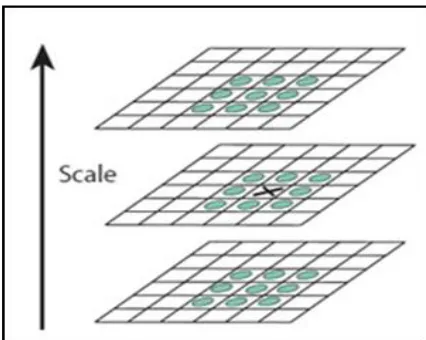
[image:4.612.161.450.355.498.2]2) Scale Invariant Feature Transform (SIFT): Scale Invariant Feature Transform (SIFT), which is a well-known technique in computer vision, was initially presented by Lowe [6] in 1999 and has been widely used to detect, recognize and describe local features in an image. SIFT can extract an object based on its particular (key) points of interest in an image with scaling, translation and rotation. A SIFT algorithm consists of four major steps: scale-space extrema detection, key point localization, orientation assignment and key point description. The first step employs a difference-of-Gaussian (DoG) function, that is D(x, y, σ), to specify the potential interest points that are invariant to scale and orientation. Then, each pixel is compared with its neighbours to obtain maxima and minima of the DoG (Figure 2). The pixels that are larger than all or smaller than all of their neighbours are chosen as potential interest points.
Fig. 1 The Building of the Gaussian and DoG Pyramid
[image:4.612.198.411.522.692.2]where Figure 1 represents the building of the Gaussian and DoG pyramid. Figure 2 represents the comparison of each pixel (i.e., the pixel marked with X) to its 26 neighbours (the pixels are marked with circles; and they are in 3 × 3 regions at the current and adjacent scales) to find the maxima and minima of the DoG images. SIFT was introduced into mobile robotics navigation systems in 2002. SIFT provides accurate object recognition with a low probability of mismatch but it is slow and when illumination changes, it is less effective.
3) Speeded Up Robust Features (SURF): A SURF algorithm, using an integral image for image convolution and a Fast-Hessian detector, was proposed by Bay, et al. First, the integral image representation of an image was created from the input image. Then, the integral image was used within a Hessian matrix to find an accurate vector of interest points. The interest points were localised by using a Tyler expansion of the scale-space function ( ). Next, the interest points and integral image were employed to extract a vector of the SURF descriptor components of the interest points [7].
SURF and SIFT techniques use slightly different methods of detecting an object’s features in an image. The detectors in both calculate the interest points in the input image but they work differently. They use the interest points to create a descriptor vector that can be compared or matched to descriptors that were extracted from other images. SURF proved to be faster than SIFT and a more robust image detector and descriptor.
Each of above-mentioned methods has its limitations in detecting an object’s features in an image. Furthermore, there are three parameters that influence the object detection process, namely: environmental conditions, target characteristics and sensor efficiency. Lighting, texture and background colour are the main environmental conditions. Sufficient texture and contrast features are the main target characteristics. Some researchers have combined and tested different image processing techniques to achieve better results. An object is detected by applying a new method that combined SIFT and a colour histogram called the Receptive Field Co-occurrence Histogram (RFCH). First, an image of the environment was captured without an object being present and then the operator placed the object in front of the camera. The object is then separated from the background by using image differentiation. Their experimental results showed that this method is robust to changes in scale, orientation and view position. In robot applications, object location and orientation relative to the robot have to be calculated and used to effect the robot’s motion. The authors compared geometrical moments and the features from Eigen-space transformation for determining object characteristics in the image. The former was less susceptible to noise.
E. Vision Based Mobile Robot Navigation
Developments in mobile robot navigation based on a vision system can be divided into indoor and outdoor navigation. The former can then be divided into map-based, map-building-based and mapless forms of navigation. The first relies on a sequence of landmarks, which the robot can detect for navigation, whereas the second involves sensors to construct the robot’s environment, so that it forms an internal map for navigation. Finally, mapless navigation is based on observing and extracting information from the elements within the robot’s environment, such as walls and objects, before it is used for navigation. Conversely, outdoor mobile robot navigation can be divided into structured and unstructured environments. These will cover obstacle avoidance, landmark detection, map building and position estimation. A structured environment requires landmarks to represent the robot’s path, whereas in an unstructured environment there are no regular properties, so a vision system must extract possible path information.
1) Visual Tracking: Visual tracking is a crucial research area because it is involved in many robot applications, such as navigation and visual surveillance. It consists of capturing an image by a camera, detecting a goal object in the image by image processing and guiding the robot automatically to track the detected object. For indoor robot navigation, tracking is widely used for service robots [8]. For example, the robot used by Abdellatif [8] tracked by following a coloured target. Colour segmentation was applied to recognize the object and then the target’s location was determined. In addition, a camera with three range sensors was used to detect obstacles and target distances. The camera and range sensors outputs were used as inputs for a controller, which enabled the mobile robot to follow the object while avoiding obstacles. Abdellatif’s work was limited to using a single colour for target detection. Furthermore, there was no option available to the robot if the object was not detected in the current view.
systems. Another study featured a visual landmark recognition system that combined an image processing board and genetic algorithms for both indoor and outdoor navigation [9]. The system can detect and evaluate landmarks that are predefined in the system’s library within the real-time image.
III.CONCLUSIONS
Vision based mobile robot navigation system is far better than the other sensor based system. More specifically, it should consider the challenges of detecting the object in the image and tackling the obstacles in its way. The navigation performance of the system should remains unaffected due to intensity of ambient light. The robot should be design in such a way that it should be able to move successfully in the unknown environment i.e. the navigation environment should not predefined.
REFERENCES
[1] Y. Zhu, T. Zhang, J. Song, and X. Li, "A New Bug-type Navigation Algorithm Considering Practical Implementation Issues for Mobile Robots," Proceedings of the 2010 IEEE International Conference on Robotics and Biometrics, pp. 531-536, Tianjin, China, 14-18 December, 2010.
[2] N. Shiltagh, L. Jalal, "Optimal Path Planning For Intelligent Mobile Robot Navigation Using Modified Particle Swarm Optimization," International Journal of Engineering and Advanced Technology (IJEAT), vol. 2, issue-4, April, 2013.
[3] P. Bhatnagar, S. Rastogi and V. Kumar, "Simulation of Path planning of Mobile Robot in Dynamic Environment," International Journal of Computer Application (IJCA), Vol. 78, September, 2013.
[4] R. Negenborn, "Robot localization and kalman flters," Master's thesis, Utrecht University, Netherlands, 2003.
[5] P. Das, S. Mandhata, C. Panda and S. Patro, "Vision based Object tracking by mobile robot," International Journal of Computer Application (IJCA), Vol. 45, No. 8, May 2012.
[6] D. G. Lowe, "Object recognition from local scale-invariant features," Proceedings of the Seventh IEEE International Conference on Computer Vision, vol.2, pp. 1150-1157, Kerkyra, Greece, 20-27 September, 1999.
[7] H. Bay, T. Tuytelaars, and L. Van Gool, "SURF: Speeded Up Robust Features." vol. 3951, A. Leonardis, H. Bischof, and A. Pinz, Eds., ed: Springer Berlin / Heidelberg, pp. 404-417, 2006.
[8] M. Abdellatif, "A vision-based navigation control system for a mobile service robot," SICE, 2007 Annual Conference, p.p 1517-1522, Kagawa University, Japan, 17-20 September, 2007.