Optimization of Working of Processor by Fins
Using FEM
M. Bisht*1, K. S. Mehra*2 *
Department of Mechanical Engineering,
BipinTripathiKumaon Institute of Technology, Dwarahat-263653, Uttarakhand, India
Abstract—In the present study, thermal analysis of electronic processor is proposed and an effort is made to decrease the maximum temperature in processor by employing straight rectangular fins which aid in rapid heat removal to the surroundings for ensuring the optimal working of the processor. Heat is generated in the processor and Heat removal is augmented by the application of fins to it. Comparative study is presented by selecting Silicon and Copper material for electronic processor, rectangular in shape enclosed by a steel casing and to it aluminum fins are attached. Modeling and Analysis carried out using Finite Element Method (FEM) based software, ANSYS APDL. Heat flows out from the processor to the surrounding through the casing and then fins attached to it. Convective boundary condition is applied to the casing and fins except the bottom which is insulated. Increase in number of fins leads to decrease in maximum temperature and increase in heat flux of the processor proportionally. The results report the temperature distribution and heat flux contour for different selection in number of fins. Conclusion are drawn from results pertaining using the appropriate number of fins to be used to optimize the maximum temperature in processor. Results show that ANSYS APDL can be used effectively and efficiently to solve challenging heat transfer problem.
His document gives formatting instructions for authors preparing papers for publication in the Proceedings of an IEEE conference.The authors must follow the instructions given in the document for the papers to be published. You can use this document as both an instruction set and as a template into which you can type your own text.
Keywords—FEM, Modeling and analysis, ANSYS APDL, Processor
I. INTRODUCTION
Microprocessors are a ubiquitous part of our lives today. However, some processors, such as those used in modern desktop computers generate a lot of heat. Because they are so small and powerful they generate too much heat to operate without a heat sink. An effective heat sink must be able to keep its processor within functional temperatures even under full load. Linton and Agonafer[1] used flotherm code to simulate detailed flow and temperature fields within a computer chassis with two fans. Similar work was also done by Yang and Fu[2]. Yu and Webb[3] analyzed the flow and heat transfer inside a computer cabinet for the high power conditions expected in desktop computers. 40W PCI card, different case fan size and different ducting positions have been studied. Chang et al.[4] reports the results of CFD analysis to cool the 30W socketed CPU of a desktop computer
dimensionless form and then presented a scheme for solving these equations. Hung et al.[9] performed numerical simulations to investigate convective-conductive heat transfer due to a laminar boundary layer flow of air over a two dimensional array of rectangular chip blocks which represent the finite heat sources.Egan et al.[10], in order to understand the thermal phenomena of embedded electronics design and to explore the thermal design space, analyzed the finite element numerical simulations, physical experimentation, and analytical models.Rodgers et al.[11], Assessed the numerical predictive accuracy for component-printed circuit board (PCB) heat transfer in forced convection using a widely used computational fluid dynamics (CFD) software. Lorenzini et al. [12] investigated by experimental means a possible use of the Vapotron Effect for the cooling of electronic devices.Davies et al.[13] presented the method to correct the thermal resistance of electronics components is to adjust the junction-to-ambient thermal resistance to account for operational conditions.Typical application of the fins are originated in the cooling devices for electronic equipment and compact heat ex-changers that used in many application such as air conditions, car radiators, etc., Incropera and DeWitt[14].
In the presented work the peak temperature of processor is optimized by selection of different number of fins for two different materials of processor.
II. MODELING AND SIMULATION
As it is evident from the diversity of application areas, the study of heat transfer and maximum temperature in processor using rectangular fin is very important for the technology of today and the near future, as developments are following the trend of miniaturization in all fields. Analysis of the heat transfer enhancement and maximum temperature reduction in processor using varying number of fins were studied extensively, but there is limited research related to the optimized working of processor using ANSYS. Processor generates heat during the course of their operation. To ensure optimal working of the component, the generated heat needs to be removed. This is done by attaching fins to the device which aid in rapid heat removal to the surroundings.
A. Problem Specification
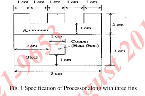
Processor is made of copper with thermal conductivity of 386 W/m-K and it generates heat at the rate of 1 W. The enclosing container is made of steel with thermal conductivity of 17 W/m-K. The fins are made of aluminum with thermal conductivity of 180 W/m-K. There is convection along all the
[image:3.612.318.565.157.321.2]boundaries except the bottom, which is insulated. The film (convection) coefficient is h=50 W/m2-K and the ambient temperature is 20ºC (Fig. 1).
Fig. 1 Specification of Processor along with three fins
An attempt is done to decrease the maximum temperature and increase the heat flux in the electronic component by varying the no. of fins to ensure the optimal working of the component.
Comparative study is done by taking silicon as a material for processor. The properties of silicon material are:
Bulk modulus : 9.8x10¹¹dyne/cm2
Melting point : 1412 °C
Specific heat : 0.7 J /g -°C
Thermal conductivity : 130 W /m-°C
Thermal diffusivity : 0.8cm2/s
Thermal expansion : 2.6x10⁻⁶/°C
B. Process Methodology 1. Preprocessing
Modeling is done in the preprocessor. Here we define the problem; the major steps in preprocessing are given below:
Define key points/lines/areas/ volumes
with a 2-D thermal conduction capability. The element has four nodes with a single degree of freedom, temperature, at each node. The element is applicable to a 2-D, steady-state or transient thermal analysis. The element can also compensate for mass transport heat flow from a constant velocity field.
Define material/geometric properties:We use the simplest thermal, isotropic, 1D material description. ANSYS has full anisotropic (completely directionally dependent), as well as non-linear material “constitutive laws”. We need to define three different materials (Copper/ Silicon, Aluminum and Steel). At first we are defining Copper then Aluminum and at the end, Steel.
Define Mesh size and meshing of geometry: Here size of element edge length is 1.
2. Solution
It includes assigning loads, constraints and solving; here we specify the constraints and finally solve the resulting set of equations.
In this problem all sides of block have convection type of boundary condition except the bottom side which is isolated and analysis type is Steady state analysis.
3. Postprocessing
After getting solution results are analyzed in postprocessing. It includes further processing and viewing of the results; in this stage we have obtained:
Lists of nodal temperatures
Temperature plots
Temperature/ heat flux contour diagrams
III. RESULTS ANDDISCUSSION
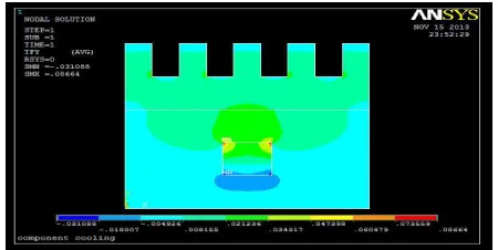
[image:4.612.327.571.104.267.2]Modeling and simulation of the specified problem is done using ANSYS APDL and contours are presented for the case, when three fins are attached to silicon and copper material processor individually.
Fig. 2 Temperature distribution contour for copper processor
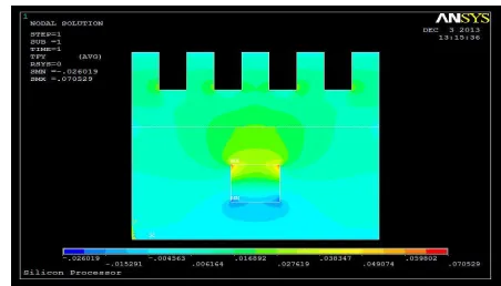
Figs.2 and 3shows the contours of temperature distribution using five fins for copper and silicon processors. By using three fins, the maximum temperature in the copper and silicon processors reduced to 396.909 K and 397.65 K, respectively.
Fig. 3 Temperature distribution contour for silicon processor
[image:4.612.331.556.539.652.2]The heat flux contours using five fins for copper and silicon processors are shown in Figs. 4 and 5. It is observed from the contours that using three fins, the heat flux in the copper and silicon processors increased to 86.64 kW/ m2and 70.529 kW/ m2, respectively.
Fig. 5 Contours of heat flux using three fins for Silicon processor
Similarly, temperature and heat flux contours are plotted for the cases when no. of fins is zero, three, seven, nine, eleven, thirteen and fourteen. Results are summarized in the form of graph for Maximum Temperature and Heat flux for different cases of fins.
Fig. 6 Variation maximum temperature along with number of fins in copper processor
Fig. 7 Variation of maximum temperature along with number of fins in silicon processor
[image:5.612.29.560.197.693.2]It is observed from the Figs 6 and 7, maximum temperature decreasing continuously as soon as reached to the higher number of fins. After using thirteen fins in processor, no considerable decrease in the maximum temperature is observed when we further increase the number of fins. Therefore, thirteen fins are sufficient to decrease the maximum temperature of the processor.
Fig. 8 Variation in heat flux along with number of fins in copper processor
If increasing the number of fins in both processors, we can see that as soon as if we reached to higher number of fins the heat flux increases continuously but after thirteen fins there is no considerable increase in heat flux, as shown in Figs. 8 and 9. Thus, thirteen fins are sufficient to use for heat transfer enhancement.
Fig. 9 Variation in heat flux along with number of fins in silicon processor
IV. CONCLUSION AND FUTURE SCOPE OF THE WORK
Thermal analysis of processor is done for ensuring its optimal working. Rectangular fins of aluminium are attached to the steel casing enclosing the processor. The results have been obtained by increasing the number of fins. The temperature distribution and heat flux contours with different selection in number of fins for two materials of processor are obtained. It is observed that the heat flux is increasing and maximum temperature is decreasing with increase in number of fins in both copper and silicon processors. But after thirteen fins, there is no considerable increase in heat flux and decrease in maximum temperature as observed. Thus, there is no need to further increase the number of fins keeping cost parameter and effective working of processor in mind.
B. Future Scope of The Work
Analysis of the thermal characteristics of processor along with different geometries of fins using ANSYS.
Cost reduction analysis of processor.
REFERENCES
[1] R.L.Linton and D. Agonafer, “Thermal model of a PC”,ASME Journal of Electronic Packaging, vol. 116, pp.134-137, 1994.
[2] R. J. Yang, andL. M. Fu, “Thermal and flow analysis of a heated electronic component,” International journal of heat and mass transfer, vol. 44, pp. 2261-2275,2001.
[3] C. W. Yu, and R. L. Webb, “Thermal design of a desktop computer system using CFD analysis”, Seventeenth IEEE SEMI- THERM SYMPOSIUM, pp. 18-26, 2001.
[4] J. Y. Chang, “ Identification of minimum air flow design for a Desktop computer using CFD modeling”, “ 7th intersociety conference on thermal and thermomechanicalPhenomena in Electronic systems”, vol. 1, pp.330-338, 2000.
[5] D.Lober, “Optimizing theintergration of an electronics system into an existing enclosure using CFDmodeling techniques”, Internationaljournal of microcircuits andelectronic packaging, vol. 22, pp.146-151, 1999.
[6] S. Subramanyam, and K.E.Crowe, “Rapid design of heat sinks for electronic cooling computational and experimental tools”, IEEE Symposium, pp. 243-251, 2000.
[7] J. H. Ryu, D. H. Choi, and S. J. Kim, “Numerical Optimization of the thermal performance of amicrochannel heat sink”, Int. J. Heatand Mass Transfer, Vol.45, pp.2823-2827, 2002.
[8] R. W. Knight, D. J. Hall, J. S. Goodling, and R. C. Jaeger, “Heat Sink Optimization with Application to Microchannels”, IEEE Transactions on Components, Hybrids, and Manufacturing Technology, vol. 15, no. 5, pp. 832-842, 1992.
[9] T. C. Hung,S. K. Wangi, and F. Peter, “Simulation of Passively Enhanced Conjugate Heat Transfer Across anArrayofVolumetricHeatSources”
CommunicationsinNumericalMethodsinEngineering, JohnWiley&Sons,Ltd. vol.13, pp. 855-866, 1997.
[10] Egan, Eric,Amon, and H. Cristina, “Thermal Management Strategies for Embedded Electronic
Components of Wearable Computers”, Journal of Electronic Packaging, vol.122, pp. 98-106,June 2000.
[11] Rodgers, J. Peter, Eveloy, C. Valerie, Davies, and R. D. Mark, “ An Experimental Assessment of Numerical Predictive Accuracy for Electronic Component Heat Transfer in Forced Convection-Part 2, Results and Discussions”, Journal of Electronic Packaging, ASME, vol.125, pp. 76-83, March 2003.
[12] Lorenzini, Giulio.,Biserni, and Cesare, “A Vepotron Effect Application for Electronic Equipment Cooling”, Journal of Electronic Packaging, ASME, vol. 125, pp. 475-479,Dec 2003.
[13] Davies, R. D. Mark, Cole, Reena, Lohan, and John, “Factors Affecting the Operational Thermal Resistance of Electronic Components”, Journal of Electronic Packaging, ASME, vol. 122, pp. 185-191,Sep 2000.