Design Development and Fabrication of Pic
Microcontroller Based Embedded System For
Temperature Monitoring
Rashid Mustafa#¹, Mohd. Junaid Khan*²
#ph.D Scholar, Department of ECE, Panjab University, India
*Assistant Professor Deptartment of ECE,SRMIET, Khora Bhura , Distt. Ambala
ABSTRACT- In this paper, Data acquisition system found wide spread application in monitoring and controlling of some physical parameter in the industry. Keeping in view the requirement of industry, this project is intended to design and develop a data acquisition system (DAQ) which is able to process the data and display it on the computer through the serial port. The heart of any DAQ system is the microcontroller, which is programmed according to the desired requirement. This project uses PIC18F4550 microcontroller which performs the enumeration, data acquisition and data transfer operations. The objective of this project is to develop hardware and software to monitor the temperature using LM35 sensor. First a voltage signal is generated from the sensor then this voltage signal is fed to microcontroller which process the signal to gives the corresponding output in digital form through its inbuilt analog to digital converter. This output is then calibrated and displayed on the computer.
Keywords—DAQ System, PIC18F4550 Microcontroller, LM35 Sensor, Wireless Data Acquisition System, MAX232, Available Power.
1-INTRODUCTION
Data acquisition systems, as the name implies, are products and/or processes used to collect information to document or analyze some phenomenon. In the simplest form, a technician logging the temperature of an oven on a piece of paper is performing data acquisition. As technology has progressed, this type of process has been simplified and made more accurate, versatile, and reliable through electronic equipment. Equipment ranges from simple recorders to sophisticated computer systems. Data acquisition products serve as a focal point in a system, tying together a wide variety of products, such as sensors that indicate temperature, flow, level, or pressure.
Present DAQ systems are based on serial or parallel port. But these ports are not absolute, so the USB based DAQ system is needed in the present time for better portability and flexibility.
In recent years there has been immense growth of USB based applications mainly due to the plug and play nature of USB and its low cost implementation. Recent PCs provide up to 8 USB ports for attaching different kinds of peripherals. The USB interface can be successfully used in
several laboratory measurement applications by interfacing a USB compatible DAQ system. Developing device drivers for custom-built USB devices have been one of the major barriers to the development of USB devices. The core feature of the present design is the implementation of USB compatible firmware in PIC microcontroller 18F4550. The microcontroller has on-chip USB transceiver and ADC. Some common data acquisition terms are shown below.
1.2 TYPES OF DATA ACQUISITION SYSTEM
1.2.1 WIRELESS DATA ACQUISITION SYSTEMS
Figure 1.1 Wireless Data Acquisition Systems[2]
1.2.2 SERIAL COMMUNICATION DATA ACQUISITION SYSTEM
Serial communication data acquisition systems are a good choice when the measurement needs to be made at a location which is distant from the computer. There are several different communication standards, RS232 is the most common but only supports transmission distances up to 50 feet. RS485 is superior to RS485 and supports transmission distances to 5,000 feet.
Figure 1.2 Serial Communication Data Acquisition Systems
1.2.2 DATA ACQUISITION PLUG-IN BOARDS
[image:3.612.253.548.103.523.2]Computer data acquisition boards plug directly into the computer bus. Advantages of using boards are speed (because they are connected directly to the bus) and cost (because the overhead of packaging and power is provided by the computer). Boards offered are primarily for IBM PC and compatible computers. Features provided by the cards can vary due to number and type of inputs (voltage, thermocouple, on/off), outputs, speed and other functions provided. Each board installed in the computer is addressed at a unique Input/Output map location. The I/O map in the computer provides the address locations the processor uses to gain access to the specific device as required by its
Figure 1.3 Data Acquisition Plug-in Boards
1.3 WORK FLOW
The summary of work flow for this project is simplified into block diagram as shown in the Figure 1.4 below. The starting point of this project is the literature review and theoretical study. But, these actions are continuous as new information must be gathered from time to time in order to proceed with this project.
Figure 1.4 Work flow of this project
2.1 COMPARISON BETWEEN 4 TYPES OF TEMPERATURE SENSOR
There are various temperature sensors available in market. The selection of sensor to be used for certain project are depends on the scope of the project. Table 2.2 below describes some of the difference in advantages and disadvantages between thermocouple, resistance thermo detector, thermistor and I.C sensor. Table 2.1 Comparison between thermocouple, RTD, thermistor and I.C sensor.
Table 2.1 Comparison Between Thermocouple, Rtd, Thermistor And I.C Sensor [13]
Software Implementation Hardware Implementation
Testing
[image:3.612.50.232.112.183.2]3- PROBLEM FORMULATION
Keeping in the various research finding as reported in reputed journal and given brief in literature survey. Further looking at the limitation the present study pertains to design development and fabrication of PIC microcontroller based embedded system for temperature monitoring of industrial plants. In the present design the following hardware, software option as given in figure will be developed.
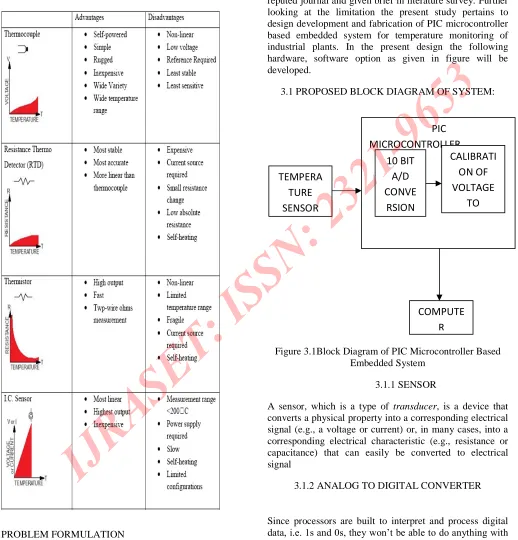
[image:4.612.39.557.125.665.2]3.1 PROPOSED BLOCK DIAGRAM OF SYSTEM:
Figure 3.1Block Diagram of PIC Microcontroller Based Embedded System
3.1.1 SENSOR
A sensor, which is a type of transducer, is a device that
converts a physical property into a corresponding electrical signal (e.g., a voltage or current) or, in many cases, into a corresponding electrical characteristic (e.g., resistance or capacitance) that can easily be converted to electrical signal
3.1.2 ANALOG TO DIGITAL CONVERTER
Since processors are built to interpret and process digital data, i.e. 1s and 0s, they won’t be able to do anything with the analog signals that may be being sent to it by a device.
TEMPERA TURE SENSOR
PIC MICROCONTROLLER
10 BIT A/D CONVE
RSION
CALIBRATI ON OF VOLTAGE
TO
So the analog to digital converter is used to convert the incoming data into a form that the processor can recognize.
3.1.3 CALIBRATION OF VOLTAGE TO TEMPERATURE
The voltage output(in volts) of the sensor is: ADC result*5/1023, The temperature in degree Celsius is: Sensor output*1000/10, = Sensor output*100.
3.1.4 ANALYSIS OF THE ACQUIRED SIGNAL
The signal is displayed on the screen i.e. in the hyper terminal window. For the design, Development and the fabrication of the system various software and hardware are required.
3.2 HARDWARE REQUIREMENTS
Hardware Requirements are there:
PIC MICROCONTROLLER 18F4550, USB Port Cable, IC –
LM35, IC -7805, IC-MAX 232and Power Supply. In this system used PIC Microcontroller 18F4550 in which inbuilt ADC and only 32 instruction is better than other microcontroller.
3. 3 SOFTWARE REQUIREMENT
The software required to implement this project is MPLAB IDE .This software is required for doing the programming in the C language for the monitoring and control program. It requires microcontroller programming in C language with PIC Burner Software and driver.
4-DESIGN DEVELOPMENT AND FABRICATION
This chapter describes the design and development of the data acquisition system for temperature monitoring. This project included the implementation of the hardware and software. The required range of temperature monitoring is from 25°C to 55°C meanwhile, the resolution of this system is 1°C. This data acquisition system will have three main important subsystems which include temperature sensor, analog to digital converter, data processing and temperature display system.
4.1 HARDWARE COMPONENTS
System consist of three parts i.e. Temperature Sensor
LM35, Microcontroller –( inbuilt A/D Converter), Power
Supply (5 Volt DC).
4.1.1 TEMPERATURE SENSOR LM 35
The LM35 series are precision integrated-circuit
temperature sensors, whose output voltage is linearly proportional to the Celsius (Centigrade) temperature. The LM35 does not require any external calibration or trimming to provide typical accuracies of (+1/4°C at room temperature and +1/4°C over a full -55 to +150°C temperature range. Low cost is assured by trimming and calibration at the wafer level. The LM35's low output impedance, linear output, and precise inherent calibration make interfacing to readout or control circuitry especially easy. It can be used with single power supplies, or with plus and minus supplies. As it draws only 60 mA from its
supply, it has very low self-heating, less than 0.1°C in still
air. The LM35 is rated to operate over a -55 to a150°C
temperature range. The LM35 series is available packaged in hermetic TO-46 transistor packages.
Features of LM 35: Calibrated directly in °Celsius (Centigrade), Linear a 10.0 mV/°C scale factor,0.5°C accuracy guarantee (at a 25°C), Rated for full -55 to a150°C range, Suitable for remote applications, Low cost due to wafer-level trimming, Operates from 4 to 30 volts,
Less than 60 mA current drain, Low self-heating, 0.08°C in
still air, Nonlinearity only +1/4°C typical, Low impedance output, 0.1 Ω for 1 mA load.
Figure 4.1a) Bottom View of LM35 b) LM35 Circuit Design c) LM35 Temperature Sensor[13]
The figure 4.1a above shows the picture of LM35, the bottom view of LM35 and the LM35 circuit design for Full-Range Centigrade Temperature Sensor. In this project, the plastic package of LM35 was choosing. This is because the package is easy to construct, small size and easy to get.
[image:5.612.312.556.402.538.2]V OUT =+1,500 mV at +150°C
= +250 mV at +25°C
= −550 mV at −55°C
4.1.2 MICROCONTROLLER
The Microchip PIC18F4550 microcontroller is a popular device for interfacing with USB. Aside from being a very full-featured PIC (by the current standards) it of course has a full-speed USB 2.0 interface built in. Since much of the existing USB example code is for this device, it makes a good starting point. The information in this article is expected to be usable on other similar USB-capable PICs (such as the lower-pin-count 18F2550, or the cheaper versions of both chips with less memory space), but conversion is up to the reader.
4.1.3 POWER SUPPLY
[image:6.612.296.571.232.462.2]The a.c. voltage across the winding of the secondary (12V/500mA) is rectified through the diode D1, D2, D3, D4 from a bridge rectifier. C1 is the filter capacitor (1000uF/10V) for the source supply. Regulator 7805 is used to gives +5V d.c. power supply for the microcontroller, MAX232 and LM35 ICs. The complete circuit diagram for power supply is given in the following fig. D2 V2 220Vac C1 1000uf L1 TRANFORMER 1 2 3 4 D1 D4 U1 7805 1 3 VIN VOUT D3 C2 .01uf
Figure 4.3 Circuit Diagram of Power Supply
4.2 USB DAQ HARDWARE
The USB DAQ hardware consists of a PIC18F4550 microcontroller and the essential components needed for USB configuration. The microcontroller has on-chip USB
[image:6.612.32.258.451.601.2]transceiver, which is connected to the host through a USB cable. The clock frequency required for the full- speed USB operation is derived from the external 20MHz crystal. A pull-up resistor internal to the microcontroller configures the USB DAQ device as a full-speed device. In the present design, the power required for PIC18F4550 operation is drawn from the bus. The on-chip ADC has 10-bit resolution. It is operated in 0 to +5 V range by applying +5 V to the VREF+ pin and by grounding the VREF- pin. The reference voltage is supplied from external source.
Figure 4.4 Circuit diagram of USB DAQ hardware
From the formulation of problem, system has been designed to acquire the temperature. Hardware was fabricated in our laboratory but implementation of the software could not be done successfully. This was due to the Unavailability of the required software and programmer. The concerned authorities at PEC, CSIO, and ISTC contacted for availability of programmer for PIC microcontroller, but could not found the programmer. Keeping in mind the above problems I switched from USB based project to send data serially on the COM port of the computer.
4.4.1 RS-232 SERIAL PORT
computer’s serial port (also known as the COM or Com port) [18]. In serial communications, the terminal end PC is called Data Terminal Equipment or DTEs and the modem is called Data communication equipment or DCEs. To obtain data from RS232 instrument and display it on PC, we need some software. There is version 4.3 of the Windmill RS232 software now available for free from their website [12]. RS stands for recommended standard. In the 60’s a committee now known as the Electronic Industries Association developed an interface to connect to connect computer to terminals to modems. The standard defines the electrical and mechanical characteristics of the connection, including the function of the signals and handshake pins, the voltage levels and maximum bit rate. A nine pin D plug has become the standard fitting for the serial ports of PCs [12]. The pin connections used are shown in Figure 4.5 and the corresponding pin assignments are shown in Table 4.1
FIGURE 4.5 RS232 DB9 PIN OUT [12]
The speed of RS232 communications is expressed in Baud. The maximum speed, according to the standard is 20000 Baud. However, modern equipment can operate much faster than this. No matter how fast or slow the connection, the maximum number of readings per second that it can take from the instrument depends on software. The length of the cable also plays a part in maximum speed. The longer the cable, the greater the cable’s capacitance that results in the slower speed which can obtain accurate results [12].
4.4.2 MAX232
The RS232 is not compatible with today’s microcontroller;
we need a line driver to convert the RS232’s signal to TTL voltage levels that will be acceptable to the PIC 18’s TX
[image:7.612.334.503.474.734.2]and RX pins. One example of such a converter is MAX232 shown in figure 4.7.
Figure 4.6 Pin Out Diagram MAX232 [14]
Feature: Operates From a Single 5-V Power Supply With 1.0-_F Charge-Pump Capacitors, Operates Up To 120
kbit/s, Two Drivers and Two Receivers, ±30-V Input
Levels, Low Supply Current . . . 8 mA Typical, ESD Protection Exceeds JESD 22, 2000-V Human-Body Model (A114-A), Upgrade With Improved ESD (15-kV HBM).
4.5 SOFTWARE IMPLEMENTATION
For software implementation, PIC Hi-tech C Compiler is used to write and compile the program of the microcontroller. Meanwhile, Extreme PIC Burner is used to load the hex file from the PIC C to the microcontroller. Other than that, Serial port is used for the user interface and monitoring the start temperature.
Initialize Controller
Enable A/D Conversion
Calibrate A/D value into Temperature value
4.6 SCHEMATIC DIAGRAM
[image:8.612.31.271.235.346.2]Figure 4.8 below shows the microcontroller circuit and its connection with the temperature sensor circuit and RS232. The input from temperature sensor circuit is connected to AN0 (pin 2) and ground (pin 14) is connected to the ground of the temperature sensor circuit. Output from the ADC is connected to personal computer through RS232 serial port.
Figure 4.8 Schematic Diagram
RESULT
The embedded system displays the temperature values at hyper terminal window. Temperature data is sent to PC serial port. The temperature can be verified while keeping multimetermeter on the output of LM35 to verify the accuracy.
Test Reading from
multimeter
Reading by
System
1 250 mV 25℃
2 300 mV 30℃
3 350 mV 35℃
SCOPE OF PROJECT
This project includes the fabrication of RS232 serial interface data acquisition system but this project can be improved further to make it USB based because its very easy to carry the USB based data acquisition system.
CONCLUSION
Data acquisition system for temperature monitoring system has been developed. This system is able to cover
the range from 25°C to 55°C with a resolution of 0.1°C.
This system consists of temperature sensor circuit, analog to digital converter and PC interface. The data collected by the microcontroller are transmitted to a PC, with an RS-232 serial connection, where they stored for different processing. The necessary firmware and the application software have also been developed. This system works successfully and gives good performance like sensitivity, reliability, easy programming.
REFERENCES
[1]. Fabrication of Microcontroller Based Multipurpose Measuring System with Inbuilt Data aquisition Sneh anand, Amit Sen Gupta 2010 IEEE.
[2]. www.omega.com
[3]. A Microcontroller Based Data Acquisition System with USB Interface M Popa , M Manu
[4]. A Platform for Building PIC Applications for Control and Instrumentation Brandon Kuczenski, Philip R. LeDuc, and William, C. Messner 2005 American Control Conference.
[5].Modeling and Formal Verification of a Commercial
Microcontroller fo Embedded System
Application,Subhashini, Balakrishan and Sofihe Tahar ICN98 December 14-16 1998
[6] Temperature-meter via USB based on PIC 18F2550 for Solar Energy Concentrator System, González Manzanilla F.O., Arízaga Silva J.A, Moreno Barrera. O
[7]. Design of USB Based Data Acquisition System Manu Mohan, A. Robson Benjamin and N. Mathivanan
[8]. A Low-cost Microcontroller-based Wireless ECG-Blood Pressure Telemonitor for Home Care Ricardo Isais, Khoi Nguyen, Gabriel Perez, Roberto Rubio, and Homyoun Nazeran IEEE September 17-21 2003
[image:8.612.29.276.469.621.2]Mehmet Demirtas*, Ibrahim Sefa*, Erdal Irmak*, and Ilhami Colak* SPEEDAM 2008
[10]. Development of a Novel Microcontroller-based Data
Logger B. Nkom ,H. Musa* IEEE 2009
[11].USB bulk transfers between a PC and a PIC microcontroller for embedded Applications Ruben Posada-Gomez, Jose Jorge Enriquez-Rodriguez, Giner Alor-Hernandez, Albino Martinez-Sibaja ERAMC 2008
[12].Microlink Engineering Solutions. Acquiring Data
from the RS232 Serial Port.
http://www.microlink.co.uk/rs232.html. (2006).
[13].Temperature Monitoring System for Ultrasound Therapy Machine By Mani A/P Chow
![Figure 4.1a) Bottom View of LM35 b) LM35 Circuit Design c) LM35 Temperature Sensor[13]](https://thumb-us.123doks.com/thumbv2/123dok_us/8588060.863015/5.612.312.556.402.538/figure-view-lm-lm-circuit-design-temperature-sensor.webp)

![Figure 4.6 Pin Out Diagram MAX232 [14]](https://thumb-us.123doks.com/thumbv2/123dok_us/8588060.863015/7.612.334.503.474.734/figure-pin-out-diagram-max.webp)

