2019 International Conference on Artificial Intelligence, Control and Automation Engineering (AICAE 2019) ISBN: 978-1-60595-643-5
A Joint Adjustment System for Distributed Logistics Equipment
Tao LIU
*, Heng-liang TANG and Fei XUE
School of Information, Beijing Wuzi University, Beijing, China
*Corresponding author
Keywords: Wireless sensor, Distributed logistics equipment, Joint adjustment.
Abstract. This paper provides a distributed logistics equipment coordination system which include
communication nodes, wireless sensor nodes and coordination system. The system can effectively monitor and adjust the parameters of the distributed logistics equipment in the system which is beneficial to on-site operation.
Introduction
With the rapid development of modern large-scale production, logistics activities such as material transportation, storage, packaging, distribution, loading and unloading are growing. Logistics equipment is important material basis of logistics system, which has the characteristics of high cost and high maintenance cost.
Logistics equipment control presents a systematic development trend. In [1,2,3,4], some suggestions and ideas are put forward on the technical innovation of automated logistics equipment under the internet of things, the application of internet of things technology in the field of warehousing logistics, and the demand of logistics technology. Chen et al. designed an automated logistics equipment which can realize the automatic delivery, sorting and transportation of goods, and comprehensively manage the site [5]. Ye et al. combined with RFID technology and other information technology, realized the automation of warehouse management, improved work efficiency and reduced operation cost [6]. Qu et al. constructed an intelligent collaborative service platform using internet of things technology, and proposed a real-time linkage method of "production-logistics" [7]. Fang et al. constructed a prototype of decision support system for the selection of storage and logistics equipment based on rule-based reasoning method [8]. Yang et al. studied the contradiction between high quality monitoring and low cost of IOT monitoring system, and mixed integer non-linear programming model that has been established [9]. Qian designed a logistics detection and application system based on wireless sensor network and its operation mechanism [10]. Li et al. presented a real-time monitoring system based on GPRS is proposed, which integrates GPRS, GPS, temperature measurement and wireless communication technology. [11]. Lei et al. introduced an embedded intelligent monitoring system for maximum utilization of solar energy. The system composition, control model and system function are described [12].
Coordination between logistics equipment is one of the important contents of logistics system automation. Reasonable coordinated control mode among logistics equipment can effectively improve the operational efficiency of logistics system.
This paper designs a joint adjustment system for distributed logistics equipment, which can improve the efficiency of logistics system and improve the overall operation of logistics system.
System Framework
System Structure
. . .
. . . .
. .
Joint Adjustment System
Wi-Fi
Wi-Fi
Wi-Fi
Wi-Fi
. . .
Wi-Fi
Wi-Fi
Wi-Fi
Wi-Fi
Controller Field Bus
Logistics Equipments
Wireless Sensor
Node Communication
Nodes
Sensor
[image:2.595.192.404.67.285.2]Sensor Sensor Sensor
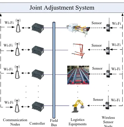
Figure 1. Structure of Joint Adjustment System for Distributed Logistics Equipment.
In the system, wireless sensor and controller adopt distributed structure, which can realize multi-monitoring point detection and multi-controller parameter setting. The on-line parameters of the controller can be adjusted according to the detection signals of wireless sensor nodes. Wi-Fi network has the characteristics of flexible location, strong anti-interference ability and easy maintenance. It is suitable for areas where wired network is inconvenient.
Distributed logistics equipment joint adjustment system is set up in the remote monitoring room. Sensors which distribute in the same way as logistics equipment detect the status data of logistics equipment and collect data through wireless sensor nodes. The communication between the controller and the logistics equipment is carried out through the fieldbus. Logistics equipment uses wireless sensor nodes and Wi-Fi network to communicate with the interfacing system. The controller uses Wi-Fi network to communicate with the joint adjustment system.
Signal Flow
The controlled parameters in logistics equipment are collected by sensors, and transmitted to the joint dispatching system through wireless sensor nodes and Wi-Fi network. According to the data collected from the logistics equipment, the system carries out data analysis and joint parameter adjustment for each controller. The signal flow of the joint adjustment system for distributed logistics equipment is shown in Figure 2.
Controller Logistics Equipments
Wireless Sensor Joint Adjustment System
Figure 2. Signal Flow Chart.
Hardware Structure
Joint Adjustment System
[image:2.595.194.404.563.639.2]Power Management Module
Storage
CPU
Data Processing Module
Wi-Fi Communication
Chip Communication
Module Host
I/O Interface
Keyboard Monitor Printer Flash Alarm Unit
Buzzing Alarm Unit
Abnormal Indicator Module
[image:3.595.192.406.70.225.2]Mouse
Figure 3. Hardware structure of Joint Adjustment System.
Power Management Module. The power management module is responsible for providing
power for data processing module, communication module, abnormal indication module, I/O interface.
Data Processing Module. This module includes CPU and Storage, which is responsible for
storing programs and processing data.
Communication Module. Wi-Fi communication chip is included in this module. It is
responsible for the establishment of a joint adjustment system to communicate with wireless sensors and controllers.
Abnormal Indicator Module. Flash alarm and buzzing alarm devices are included in the
module. They are responsible for the output of abnormal signals when abnormal events occur in the operation of the host.
I/O Interface. It is responsible for data exchange with keyboard, mouse, display, printer and other external devices.
Controller
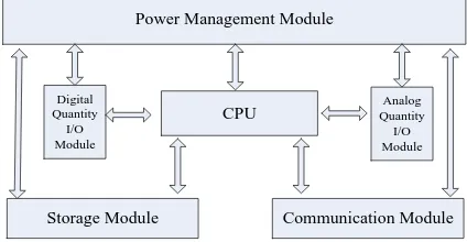
The controller consists of power management module, storage module, communication module, CPU, digital quantity I/O module and analog quantity I/O module. The hardware structure is shown in Figure 4.
CPU Digital
Quantity I/O Module
Analog Quantity
I/O Module
Storage Module
Power Management Module
Communication Module
Figure 4. Hardware Structure of Controller.
Power Management Module. It is responsible for providing power for storage module,
communication module, CPU module, digital I/O module and analog I/O module.
CPU. The CPU is responsible for executing user programs and processing data.
Storage Module.It is used as a storage system program and user program.
Communication Module. Communication module is needed to connect the intermodulation
system with the controller.
Digital quantity I/O Module and Analog Quantity I/O Module. The functions of data
[image:3.595.191.403.509.619.2]Wireless Sensor Nodes
[image:4.595.186.412.133.270.2]Wireless sensor nodes include power management module, data acquisition module, data processing module, communication module and abnormal indicator module. The hardware structure is shown in Figure 5.
Power Management Module
Storage
CPU Data Processing
Module
Wi-Fi Communication
Chip Communication
Module
Abnormal Indicator Module Flash Alarm Buzzing Alarm Sensor
A/D Converter
[image:4.595.187.401.503.644.2]Data Acquisition Module
Figure 5. Hardware Structure of Wireless Sensor Nodes.
Power Management Module. It provides power for data acquisition module, data processing
module, communication module and abnormal indicator module.
Data Acquisition Module. The module includes sensor and A/D converter, which is responsible
for detecting the operation data of logistics equipment.
Data Processing Module.CPU and memory are included. It is responsible for data storage and
data processing.
Communication Module.It is composed of Wi-Fi communication chip, which is responsible for
establishing communication between wireless sensor and intermodulation system.
Abnormal Indicator Module. This module includes flash alarm and buzzing alarm device.
When the wireless sensor itself or the detection of anomalies occurs, the output abnormal signal.
Working Mode of Joint Adjustment System
Logical Structure of Joint Adjustment System
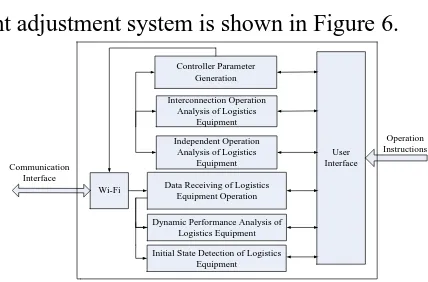
The logical structure of joint adjustment system is shown in Figure 6.
Controller Parameter Generation
User Interface Data Receiving of Logistics
Equipment Operation
Dynamic Performance Analysis of Logistics Equipment Independent Operation
Analysis of Logistics Equipment Interconnection Operation
Analysis of Logistics Equipment
Wi-Fi
Operation Instructions Communication
Interface
Initial State Detection of Logistics Equipment
Figure 6. Logical Structure of Joint Adjustment System.
Controller parameter generation, interconnection operation analysis of logistics equipment, independent operation analysis of logistics equipment, data receiving of logistics equipment operation, dynamic performance analysis of logistics equipment, initial state detection of logistics equipment constitutes the core of working mode.
Wi-Fi realizes the communication among the system, controller and wireless sensor nodes. Operators can view the current status of logistics equipment and controller parameters through the user interface. At the same time, they can also set controller parameters according to need.
Workflow of Joint Adjustment System
When the joint adjustment system is in the networking mode, wireless sensor nodes constantly detect the controlled parameters of logistics equipment and send them to the joint dispatching system. After data analysis, the parameters of the controller are sent to the controller through Wi-Fi network to realize the control of logistics equipment.
The workflow of the joint adjustment system is as follows:
Step1: Start up the adjustment system and logistics equipment. Open the Wi-Fi
communication of the joint adjustment system and establish the connection among the joint dispatching system, controller and logistics equipment.
Step2: Check the initial state of logistics equipment to determine whether the operation status of logistics equipment is normal. If it is normal, Step4 is executed. If it is not normal, Step3 is executed.
Step3: If the initial state of the equipment is abnormal, repair the logistics equipment. Step 4 is executed.
Step4: Start independent operation analysis of logistics equipment. According to the operation data, the parameters of the independent logistics equipment controller are set and sent.
Step5: Check the operation status of independent logistics equipment running. If it is normal, Step6 is executed. If it's not normal, Step4 is executed.
Step6: Start logistics equipment interconnection operation analysis. According to the operation data, the parameters of logistics equipment controller for interconnected operation are set and sent.
Step7: Check the operation status of the interconnected logistics equipment. If it is normal, Step10 will be executed. If it is not normal, Step6 will be executed.
Step8: Controller parameter setting is completed. Return to Step2.
Summary
This paper designs a joint adjustment system for distributed logistics equipment. The joint dispatching system can detect the dynamic data of the operation of distributed logistics equipment. According to the data obtained, the parameters of the controller are obtained. The parameters of the controller are transmitted to the controller through Wi-Fi network to ensure the normal operation of the whole system. Operators can also view the parameters of the controller and the operation status of logistics equipment.
Acknowledgment
This paper is supported by General Program of Science and Technology Development Project of Beijing Municipal Education Commission of China (No.KM201710037001), Beijing Key Laboratory of Intelligent Logistics System (No. BZ0211), Beijing Intelligent Logistics System Collaborative Innovation Center (PXM2018_014214_000009).
References
[1] G. S. Liu, Research on development and application of automated logistics equipment based on internet of things, Automation & Instrumentation. 6 (2015) 71-73.
[3] Y. Xu, L. Wang, Y. Q. Wang, Development and application of automated logistics equipment under internet of things, Technology and Economic Guide. 2 (2017) 35.
[4] A. M. Ma, Y. M. Hu, G. Y. Wang, Techniques of internet of things in the application research of industrial automation, Techniques of Automation and Applications. 32 (2013) 117-119.
[5] L. M. Chen, Z. Zhao, Z. N. Yu, Design and application of automatic logistics equipment based on internet of things, Techniques of Automation and Applications. 38 (2019) 88-91.
[6] J. Ye, G. Tian, Application of RFID technology in warehouse management system automation, Technological Development of Enterprise. 31 (2012) 75-76.
[7] T. Qu, D. Y. Jia, Z. Z. Wang, H. Luo, G.Q. Huang, “Manufacturing-logistics” real-time joint methed and system based on IOT, Logistics Sci-Tech. 7 (2014) 1-4.
[8] D. J. Fang, X. D. Hu, Design of decision-support system of selection of warehousing logistics equipment based on knowledge base, Logistics Technology. 32 (2013) 409-412.
[9] B. Yang, Y. Y. Hao, J. Li, Nodes deployment approach of internet of things for monitoring applications, Computer Engineering and Science. 36 (2014) 1255-1261.
[10] J. Qian, Study on logistics detection and application system based on WSN technology, Logistics Technology. 33 (2014) 451-453.
[11] X. Li, T. Yuan, Real-time monitoring system design for cold-chain logistics, Transducer and Microsystem Technologies. 33 (2014) 131-133.