Contact Stress Analysis of Helical Gear by Using AGMA and
ANSYS
S.Sai Anusha
1P.Satish Reddy
2P.Bhaskar
3M Manoj
4 PG Scholar, Assoc. Professor , Asst Professor, Asst ProfessorDept of Mechanical Engineering, Prasiddha College of Engg & Tech, Amalapuram
[email protected],[email protected],[email protected],[email protected]
ABSTRACT:
Gears are one of the most critical components in mechanical power transmission systems. The gears are generally used to transmit power and torque. The efficiency of power transmission is very high when compared to other kind of transmission. In the gear design the bending stress and surface strength of the gear tooth are considered to be one of the main contributors for failure of the gears in gear set. The analysis of stresses has become popular as an area of research on gears to minimize and reduce the failures. The present investigation is carried out to make use of helical gear, by analyzing the contact stresses for different Pressure angles (14.5˚,16˚,18˚,20˚) Helix angles (15˚,20˚,25˚,30˚)and(80mm,90mm,100mm,110mm, 120mm) Facewidth. A Three-dimensional solid model is generated by Pro-E that which is powerful and modern solid modeling software .The numerical solution is done by Ansys, which is a finite element analysis package. The analytical approach is based on contact stress equation, to determine the contact stresses between two mating gears. The results obtained from Ansys values are compared with theoretical values are in close agreement. The present analysis is useful in quantifying the above said parameters that helps in safe and efficient design of the helical gear.
Key words: Helical gear, AGMA, Ansys, Pressure angle, Helix angle, Face width.
I.INTRODUCTION
One of the best methods of transmitting power between the shafts is gears. Power transmission has always been of high importance. The efficiency of any machine depends on the
stresses of helical gear set with localized bearing contact by using finite element analysis.
S.Vijayaragan etal [6] carried out a static analysis of composite helical gears using three dimensional finite element methods to study the displacements and stresses at various points on a helical gear tooth. For determining the stresses at any stage during the design of gears helix angle and face widths are important. Muthuveerappan etal [7] have explained the geometry of helical gears by simple mathematical equations. Based on the above reviews shows that plenty of work has been done on helical gears. Hence this paper mainly aims to study the effect of contact stress on helical gears due to changes in helix angle, face width and pressure angle.
Table: 1 Parameters of Helical gear:
S.No Description Value 1 Pressure angle 20˚
2 Helix angle 20˚
3 Face width(mm) 120 4 Module(m) (mm) 10
5 No. of Teeth 30
6 Pitch diameter(mm) 300 mm
7 Addendum(mm) 1m
8 Dedendum(mm) 1.25m
9 Modulus of elasticity 210 X 10 3 N/mm2 10 Poisson’s ratio 0.3
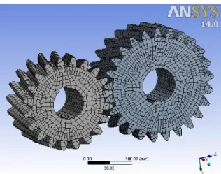
II. DESIGN OF HELICAL GEAR
Fig -1: Mechanical Windows
The procedure to model the gear of 20 number of teeth with the combination of the all above mentioned parameters in the Pro/Engineer
Wildfire, other set of gears are modeled in the similar way. Part parameters are the basic parameters defining the gear. These part parameters determine all the other parameters that define the gear tooth profile using the tools/relation menu.
Fig: 2 Finite element meshing on helical gear
Fig-3: Fixed Support
Fig-4: Moment Applied
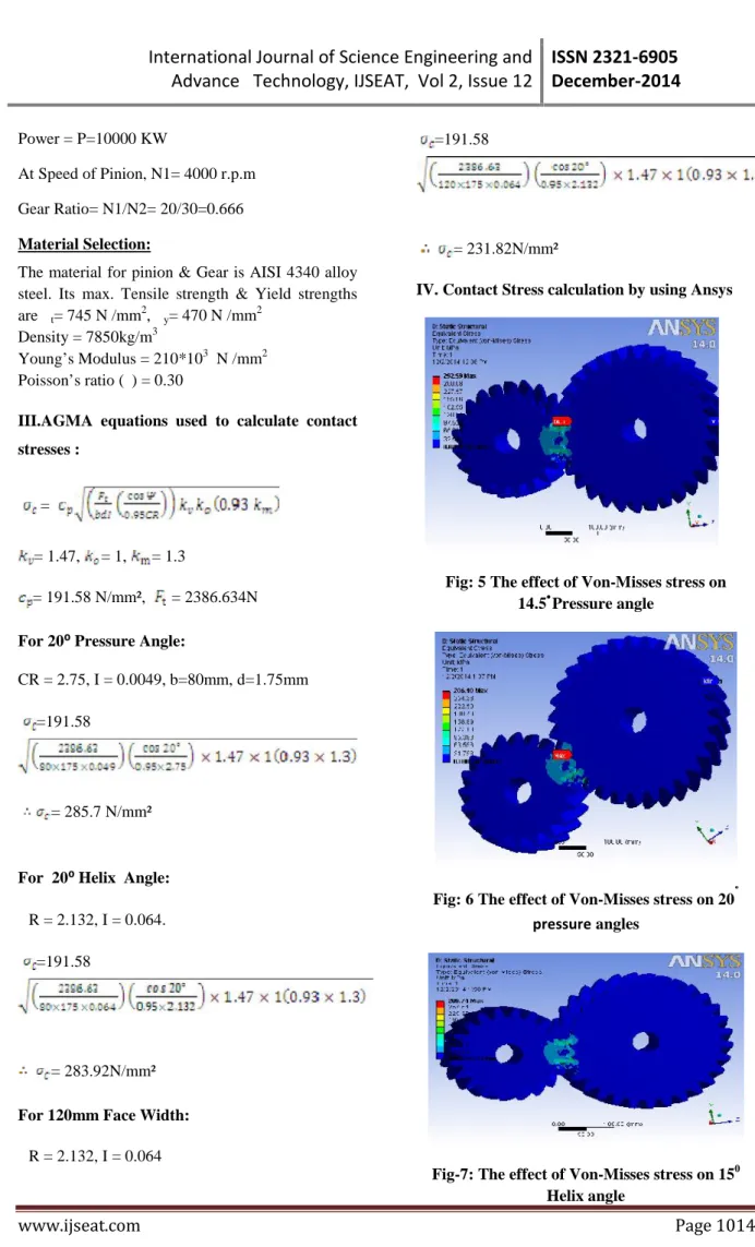
Power = P=10000 KW
At Speed of Pinion, N1= 4000 r.p.m
Gear Ratio= N1/N2= 20/30=0.666
Material Selection:
The material for pinion & Gear is AISI 4340 alloy steel. Its max. Tensile strength & Yield strengths are σt= 745 N /mm
2
, σy= 470 N /mm 2
Density = 7850kg/m3
Young’s Modulus = 210*103 N /mm2
Poisson’s ratio (ν) = 0.30
III.AGMA equations used to calculate contact
stresses :
=
= 1.47, = 1, = 1.3
= 191.58 N/mm², = 2386.634N
For 20⁰Pressure Angle:
CR = 2.75, I = 0.0049, b=80mm, d=1.75mm
=191.58
= 285.7 N/mm²
For 20⁰Helix Angle:
СR = 2.132, I = 0.064.
=191.58
= 283.92N/mm²
For 120mm Face Width:
СR = 2.132, I = 0.064
=191.58
= 231.82N/mm²
IV. Contact Stress calculation by using Ansys
Fig: 5 The effect of Von-Misses stress on 14.5˚Pressure angle
Fig: 6 The effect of Von-Misses stress on 20˚ pressureangles
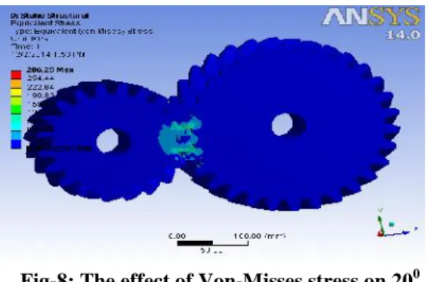
Fig-8: The effect of Von-Misses stress on 200 Helix angle
Fig: 9 The effect of Von-Misses stress for 80mm Face Width
Fig-10: The effect of Von-Misses stress For 120mm Face Width
V. RESULTS AND DISCUSSIONS
Table: 2 Pressure Angle Vs Theoretical and Ansys Stress Values.
Pressure Angle
Theoretical Stress(N/mm2)
Ansys Results(N/mm2)
14.5˚ 289.9 292.59
16˚ 288.9 291.87
18˚ 287.4 289.03
20˚ 285.7 286.18
Table: 3 Helix Angle Vs Theoretical and Ansys Stress Values.
Helix Angle
Theoretical Stress(N/mm2)
Ansys Results(N/mm2)
15˚ 285.7 289.74
20˚ 283.88 286.25
25˚ 310.57 284.98
30˚ 385.64 282.63
Table: 4 Face Width Vs Theoretical and Ansys Stress Values.
Face Width(mm)
Theoretical stress(N/mm2)
Ansys Results(N/mm2)
80 283.91 286.35
90 267.68 273.45
100 253.94 264.85
110 242.12 253.27
120 231.81 231.44
Fig: 11 Pressure angle vsAGMA and Ansys
The effect of pressure angles on contact stress is studied by varying the pressure angles shown in fig: 11. It can be observed that the variation in the magnitude of stress to pressure angles. When compared, AGMA values are little lower than the Ansys values. Finally at 20˚ pressure angle the
Fig: 12 Helix angle Vs AGMA and Ansys
The effect of helix angle on contact stress is studied by varying the helix angle for four different angles are 15˚, 20˚, 25˚, 30˚. A typical trend has been observed when the 15˚ helix angle stress value is 285.7 high when compared to 20˚helix angle. The highest stress was developed at 25˚ helix angle among the other helix angles the comparison of analytical and Ansys stress values are little lower than the 15˚and 20˚helix angles.
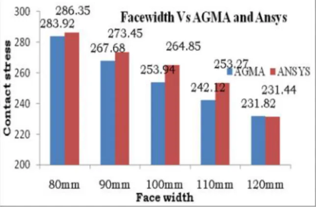
Fig: 13
Face width
vsAGMA and AnsysThe effect of face width on Von-Mosses stress is studied by varying the face width for different values are(80mm,90mm,100mm,110mm&120mm) respectively. A steady rate of stress values can be observed in above graph except for 120mm face width. The results are indicated that as the face width increases contact stress decreases. When compare with the ANSYS and AGMA stress values
are little higher than theoretical values
.
VI CONCLUSIONS
1. Pressure angles, helix angles and face widths are important geometrical parameters in determining the state of stresses during the design of gears.
2. By observing the analysis results, the stress values obtained are less than their yield stress. So we can decide that our design is safe under working conditions.
3. This above parameters can be correlated that good contact ratio of gears low stress was developed.
4. The helix angle, pressure angle and face width values of helical gear obtained using AGMA equation is little higher than Ansys values.
5. During the contact of gear and pinion, the contact stress is decreased with the increase of face width.
VII.REFERENCES
[1] B.Venkatesh, V.Kamala, and A.M.K.prasad, Design, modeling and Manufacturing of helical gear, ISSN 0976-4259, 2010
[2] Pushpendra Kumar, Mishra and Dr.M.S.Murthy, Comparison of Bending stress for Different Face width of helical Gear Obtained Using MATLAB Simulink with AGMA and Ansys ISSN 2231-5381, 2013.
[3] Prashant patil, Narayan Dharashiwkar, krishna kumar josh and Mahesh Jadhav, 3D Photo elastic and Finite Element Analysis of Helical Gear, ISSN 1821-1259,2011.
[4] Khailash C.Bhosale,Analysis of Bending Strength of helical Gear by FEM, ISSN 2222-1727,2011
[5] Cheng Y, and Tsay C.B, Stress analysis of Helical Gear set with Localized Bearing Contact, Finite Element in Analysis and Design, PP.707-723, 2002.
[6] Rao C.M, and Muthuveerappan G, Finite Element Modeling and Stress Analysis of Helical Gear, Teeth, Computers & structures, PP.1095-1106, 1993.
[7] V.B.Bhandari., Design of Machine Elements, Tmh, 2003.
[8] R.S.Khurmi., Machine Design, Schand, 2005. [9] Ivana Atanasovska and Vera Nikolic (2009), “Finite Element Model for Stress Analysis and Nonlinear Contact Analysis of Helical Gear”, pp. 61-68.