Research Article
Integral Equation Analysis of EM Scattering from
Multilayered Metallic Photonic Crystal Accelerated with
Adaptive Cross Approximation
Jianxun Su,
1Zengrui Li,
1Xujin Yuan,
2Yaoqing (Lamar) Yang,
3and Junhong Wang
41Electromagnetic Laboratory, Communication University of China, Beijing 100024, China 2Science and Technology on Electromagnetic Scattering Laboratory, Beijing 100854, China
3Department of Computer and Electronics Engineering, University of Nebraska-Lincoln, Lincoln, NE 68182, USA 4Institute of Lightwave Technology, Beijing Jiaotong University, Beijing 100044, China
Correspondence should be addressed to Jianxun Su; sujianxun [email protected] Received 6 March 2015; Accepted 8 July 2015
Academic Editor: Luis Landesa
Copyright © 2015 Jianxun Su et al. This is an open access article distributed under the Creative Commons Attribution License, which permits unrestricted use, distribution, and reproduction in any medium, provided the original work is properly cited. A space-domain integral equation method accelerated with adaptive cross approximation (ACA) is presented for the fast and accurate analysis of electromagnetic (EM) scattering from multilayered metallic photonic crystal (MPC). The method directly solves for the electric field in order to easily enable the periodic boundary condition (PBC) in the spatial domain. The ACA is a purely algebraic method allowing the compression of fully populated matrices; hence, its formulation and implementation are independent of integral equation kernel (Green’s function). Therefore, the ACA is very well suited for accelerating integral equation analysis of periodic structure with the integral kernel of the periodic Green’s function (PGF). The computation of the spatial-domain periodic Green’s function (PGF) is accelerated by the modified Ewald transformation, such that the multilayered periodic structure can be analyzed efficiently and accurately. An effective interpolation method is also proposed to fast compute the periodic Green’s function, which can greatly reduce the time of matrix filling. Numerical examples show that the proposed method can greatly save the frequency sweep time for multilayered periodic structure.
1. Introduction
Photonic crystals [1] are periodic structures of great interest
for their applications both in the microwave region and in the optical range. The main feature is the presence of frequency bands wherein the waves are highly attenuated and cannot propagate. It results from the removal of degeneracies of the free-photon states at the Bragg planes provoked by the periodicity, which produces forbidden frequency gaps so-called photonic band gaps (PBGs). This property is exploited in the electromagnetic and optical applications.
Many numerical methods for computing such band structures have been adapted from solid-state physics. They include, but are not restricted to, plane-wave expansions
[2], the Korringa-Kohn-Rostoker method [3], and shell
methodologies [4]. Over the past two decades, finite
dif-ference time domain (FDTD) [5] has been widely used in
computational optics and photonics. Recent developments include specialized versions of the finite element method
(FEM) [6] and the flexible local approximation method
[7]. FDTD and FEM can cope with arbitrary complicated
shapes and materials. However, the radiation into unbounded regions requires either absorbing boundary conditions or perfectly matched layers, and special measures need to be taken into account when employing these conditions to the scattered field formulation. For open-region problems, integral equation/method of moments (IE/MoM) has a great advantage.
The ACA is a purely algebraic method, which is inde-pendent of the kernel. The ACA was originally introduced in
2000 by Bebendorf [8] and since then has been successfully
applied for integral formulations involved electromagnetic
scattering [9,10]. The integral kernel is a free space Green’s
function. In addition, it is noted that most photonic crystal
Volume 2015, Article ID 274307, 7 pages http://dx.doi.org/10.1155/2015/274307
applications deal with two-dimensional (2D) structures that are invariant along a longitudinal axis and periodic in the
transverse plane [11]. The manufacture of a 2D photonic
crystal structure is easier than that of three-dimensional (3D)
one [12].
In this paper, a space-domain integral equation acceler-ated with ACA is presented for the fast and accurate analysis of electromagnetic scattering from 2D and 3D multilayered periodic structures. The ACA is first introduced for surface integral equation with the kernel of periodic Green’s function (PGF). The ACA can be applied to compress impedance matrix blocks and accelerate matrix-vector multiplication (MVP) for reducing computational complexity. A modified Ewald transformation is proposed to efficiently compute the PGFs. Compared with traditional Ewald method, it has less computational cost and can eliminate the imbalance of two Ewald sequences for multilayered periodic structure. An efficient interpolation method is also proposed to fast compute the PGFs and then accelerate impedance matrix filling. Our proposed method can effectively reduce the frequency sweep time for multilayered periodic structure involving a lot of unknowns.
2. Formulation
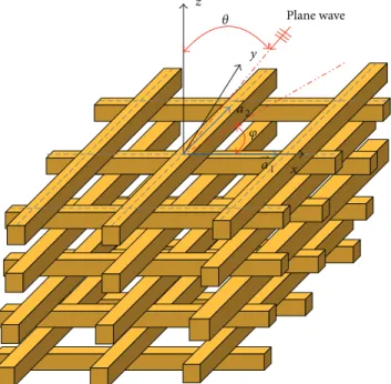
Figure 1 shows the multilayered double periodic structure with identical metallic objects of arbitrary shape periodically
repeated in the𝑥𝑦-plane.⇀𝑎1and⇀𝑎2are the primitive lattice
vectors.𝐴 = |⇀𝑎1× ⇀𝑎2|is the cross-sectional area of the unit
cell.⇀𝐸𝑖 = (̂𝜃cos𝛼 + ̂𝜑sin𝛼)𝐸0exp(−𝑗𝛽̂𝑘 ⋅ ⇀𝑟)is the incident
electric field.𝛼is the polarization angle. The wave number is
𝛽 = 𝜔√𝜇𝜀and̂𝑘 = −(̂𝑥sin𝜃𝑖cos𝜑𝑖+ ̂𝑦sin𝜃𝑖sin𝜑𝑖+ ̂𝑧cos𝜃𝑖).
The wave vector is⇀𝑘 = 𝛽̂𝑘and phase shift⇀𝑘𝑡00 =⇀𝑘 |𝑡. The
array is assumed to be periodic in the𝑥𝑦-plane and the cell of
the array is obtained by shifting the cell through the relation
⇀𝜌
𝑚𝑛= 𝑚⋅⇀𝑎1+𝑛⋅⇀𝑎2.⇀𝜌𝑚𝑛is defined as the translation vector
of the lattice.
2.1. Integral Equation. In this paper, we consider the metallic
photonic crystal. Let𝑆be the surface of a metallic object. By
enforcing the boundary conditions that the total tangential electric field is zero on the perfect electric conductor (PEC)
surface𝑆, the electric field integral equation (EFIE) is given
as [13] 𝑗𝜔𝜇 [∫ [⇀𝐽𝑠(⇀𝑟) + 1 𝛽2∇⋅ ⇀𝐽 𝑠(⇀𝑟) ∇ ] ⋅ 𝐺𝑝(⇀𝑟,⇀𝑟) 𝑑𝑠] 𝑡= ⇀𝐸inc 𝑡 , (1)
where 𝐺𝑝 is a doubly periodic Green’s function. The
Rao-Wilton-Glisson (RWG) basis functions on triangular
ele-ments are employed to discretize the electric current [14]. In
addition, the special basis and test functions derived from RWG basis function are introduced to ensure current
con-tinuity across the periodic boundaries [15]. The application
of the Floquet-Bloch theorem reduces the computational
x y z Plane wave 𝜃 𝜑 ⇀ a1 ⇀ a2
Figure 1: Multilayered periodic structure with a general skewed lattice.
domain of infinite periodic structures to a single unit cell but leads to the numerical evaluation of very slowly converging series.
2.2. Modified Ewald Transformation. We propose the follow-ing strategy to compute the spatial periodic Green’s function
in an arbitrary point⇀𝑢 = ⇀𝑟 − ⇀𝑟.
If𝑢𝑧= |𝑧 − 𝑧| >0.5√𝐴, PGF is computed by its spectral representation with exponential convergence, and thus no
acceleration technique is required [16]. Consider
𝐺𝑝(⇀𝑟,⇀𝑟) = ∞ ∑ 𝑚=−∞ ∞ ∑ 𝑛=−∞ 𝑒−𝑗⇀𝑘𝑡𝑚𝑛⋅(⇀𝜌 −⇀𝜌) 2𝑗𝐴𝑘𝑧𝑚𝑛 𝑒 −𝑗𝑘𝑧𝑚𝑛|𝑧−𝑧|, (2) where ⇀𝑟 = ⇀𝜌+𝑧⋅ ̂𝑧, ⇀𝑘 𝑡𝑚𝑛=⇀𝑘𝑡00+2𝐴𝜋[𝑚 (⇀𝑎2× ̂𝑧) + 𝑛 (̂𝑧 × ⇀𝑎1)] (3)
is the reciprocal lattice vector. Consider
𝑘𝑧𝑚𝑛= √𝑘2
0−⇀𝑘𝑡𝑚𝑛⋅⇀𝑘𝑡𝑚𝑛, (4)
where Re(𝑘𝑧𝑚𝑛) ≥0, Im(𝑘𝑧𝑚𝑛) ≤0.
If 𝑢𝑧 = |𝑧 − 𝑧| < 0.5√𝐴, PGF is computed by the
representation of Ewald transformation [17], which are two
exponential converging series. Consider
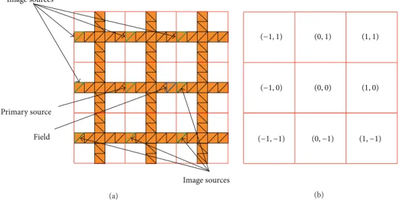
Primary source Field Image sources Image sources (a) (−1, 0) (0, 0) (1, 0) (−1, −1) (0, −1) (1, −1) (−1, 1) (0, 1) (1, 1) (b)
Figure 2: (a) Periodic image sources in triangular boundary mesh. (b) Corresponding lattice numbers.(0,0)lattice is the primary unit cell.
where 𝐺𝑝1(⇀𝑟,⇀𝑟) = ∑∞ 𝑚=−∞ ∞ ∑ 𝑛=−∞ 𝑒−𝑗⇀𝑘𝑡𝑚𝑛⋅(⇀𝜌 −⇀𝜌) 4𝑗𝐴𝑘𝑧𝑚𝑛 ⋅ [𝑒−𝑗𝑘𝑧𝑚𝑛(𝑧−𝑧)erfc(𝑗𝑘𝑧𝑚𝑛 2𝐸 − (𝑧 − 𝑧 ) 𝐸) + 𝑒𝑗𝑘𝑧𝑚𝑛(𝑧−𝑧)erfc(𝑗𝑘𝑧𝑚𝑛 2𝐸 + (𝑧 − 𝑧 ) 𝐸)] , (6) 𝐺𝑝2(⇀𝑟,⇀𝑟) = ∑∞ 𝑚=−∞ ∞ ∑ 𝑛=−∞ 𝑒−𝑗⇀𝑘𝑡00⋅⇀𝜌𝑚𝑛 4𝜋𝑅𝑚𝑛 ⋅real[𝑒𝑗𝑘0𝑅𝑚𝑛erfc(𝑅 𝑚𝑛𝐸 +2𝑗𝑘𝐸)] , (7)
where erfc(𝑧)is the complementary error function of
com-plex argument and𝑅𝑚𝑛= |⇀𝑟 − ⇀𝑟− ⇀𝜌𝑚𝑛|.
By analyzing the asymptotic behavior of the series terms, the approximation to the optimal value for general skewed lattices is given by
𝐸 =max(√𝜋
𝐴, 𝑘
2𝐻) , (8)
where𝐻2is the maximum exponent permitted. In almost all
practical cases it is sufficient to include only nine terms in(6)
and(7)(i.e., the summation limits are from−1 to +1), in which
the error is usually less than 0.1%.
For multilayered periodic structure, when𝑢𝑧= |𝑧 − 𝑧| >
0.5√𝐴, the PGFs are computed by their spectral
represen-tation rather than direct Ewald transformation. In doing so there are two advantages.
(1) The spectral representation just requires evaluation of the exponential function, which is much simpler than
the computation of complex-argument
complemen-tary error function (erfc). Compared with erfc(𝑧),
the computational complexity of the exponential
function exp(𝑧)can be ignored.
(2) In addition, it can eliminate the imbalance of two
Ewald sequences when𝑢𝑧is too large. For the
multi-layered structure, the complementary error functions
in the first terms(𝑚 = 𝑛 = 0)of both Ewald series
will take large imaginary arguments when𝑢𝑧 is too
large. These two terms will have very large values that are approximately equal in amplitude, but of opposite signs, so that summing them up will lead to a severe loss of accuracy due to the finite machine precision.
2.3. Singularity Extraction. When the distance between the
observation point⇀𝑟 and the source point⇀𝑟 or one of its
periodic extensions is electrically small, the contribution to Green’s function is essentially quasistatic. Usually the center
distance between source and field triangles is less than0.1𝜆;
then both are considered to be “near interaction.” Singular
terms in(5) and (7) often arise, for example, from one of
nine spatial terms𝑅𝑚𝑛with𝑚, 𝑛 = −1, 0or +1, depending on
which term represents the source nearest to the observer⇀𝑟.
By extracting its singularity [18], the PGF can be expressed
as𝐺𝑝 = 𝐺𝑝1 + [𝐺𝑝2 − 1/(4𝜋𝑅)] + 1/(4𝜋𝑅). The singularity
subtraction technique [19] used in this paper can compute the
singularity of|⇀𝑟 − ⇀𝑟|𝑛 (𝑛 ≥ −3)type.
Supposing the source point nearest to the observer point
appears at (1,0) term rather than(0,0) term as shown in
Figure 2, the primary source point can be transferred to(1,0)
lattice. Then, the singular term always appears at(0,0)term
𝐺00𝑝2. The singularity of𝐺00𝑝2can be extracted as
𝐺00𝑝2(⇀𝑟,⇀𝑟) = 𝐹𝑝200(⇀𝑟,⇀𝑟) + 1
o ⇀ a2 ⇀ a1 Gn𝑥,n𝑦,n𝑧 Gn𝑥+1,n𝑦,n𝑧 Gn𝑥+1,n𝑦+1,n𝑧 Gn𝑥,n𝑦+1,n𝑧 Gn𝑥+1,n𝑦,n𝑧+1 Gn𝑥,n𝑦+1,n𝑧+1 Gn𝑥,n𝑦,n𝑧+1 Gn𝑥+1,n𝑦+1,n𝑧+1 dx dy dz G(⇀u )
Figure 3: Depiction of trilinear interpolation of PGF.
where𝐹𝑝200is the nonsingular part
𝐹𝑝200(⇀𝑟,⇀𝑟) = 1 4𝜋𝑅 ⋅real{𝑒−𝑗𝑘0𝑅⋅erfc(𝑅𝐸 −𝑗𝑘0 2𝐸) −erfc(− 𝑗𝑘0 2𝐸)} . (10)
As𝑅 → 0, the result of applying L’ Hˆopital’s rule on(10)is as follows: lim 𝑅 →0𝐹 00 𝑝2(⇀𝑟,⇀𝑟) = 1 2𝜋⋅real[−𝑗𝑘0erfc(− 𝑗𝑘0 2𝐸) − 2𝐸 √𝜋𝑒𝑘 2 0/4𝐸2] . (11)
2.4. Interpolation of PGF. PGFs are very smooth and amenable to interpolation. Fast interpolation of PGFs can greatly reduce the time of matrix filling. The reason is that interpolating the PGF values from the table is much faster than directly computing the Ewald sums (since this has to be done for every pair of source and field triangles in the numerical integration using cubature formulas). Trilinear
interpolation [20] suited for the calculation of
complex-valued function with very high efficiency is applied here.
As shown inFigure 3, the cuboid grouping the unit cell is
equally divided into many subgrids with side length𝐿. Yellow
points are the precomputed PGFs at the corner of the subgrid. Then the three-dimensional PGF values can be obtained by trilinear interpolation: 𝐺 (⇀𝑢 ) = (1− 𝛼𝑥) (1− 𝛼𝑦) (1− 𝛼𝑧) 𝐺𝑛𝑥+1,𝑛𝑦+1,𝑛𝑧+1 + (1− 𝛼𝑥) (1− 𝛼𝑦) 𝛼𝑧𝐺𝑛𝑥+1,𝑛𝑦+1,𝑛𝑧+2 + (1− 𝛼𝑥) 𝛼𝑦(1− 𝛼𝑧) 𝐺𝑛𝑥+1,𝑛𝑦+2,𝑛𝑧+1 + (1− 𝛼𝑥) 𝛼𝑦𝛼𝑧𝐺𝑛𝑥+1,𝑛𝑦+2,𝑛𝑧+2 + 𝛼𝑥(1− 𝛼𝑦) (1− 𝛼𝑧) 𝐺𝑛𝑥+2,𝑛𝑦+1,𝑛𝑧+1 + 𝛼𝑥(1− 𝛼𝑦) 𝛼𝑧𝐺𝑛𝑥+2,𝑛𝑦+1,𝑛𝑧+2 + 𝛼𝑥𝛼𝑦(1− 𝛼𝑧) 𝐺𝑛𝑥+2,𝑛𝑦+2,𝑛𝑧+1 + 𝛼𝑥𝛼𝑦𝛼𝑧𝐺𝑛𝑥+2,𝑛𝑦+2,𝑛𝑧+2, (12) where𝛼𝑥= 𝑑𝑥/𝐿,𝛼𝑦= 𝑑𝑦/𝐿, 𝛼𝑧= 𝑑𝑧/𝐿.
The relative error𝜀obtained by interpolating the PGFs is
defined as
𝜀 =
𝐺int− 𝐺ex
𝐺ex , (13)
where 𝐺int and 𝐺ex are the interpolated and the exact
data, respectively. The exact data are obtained by the above
accelerating method with an accuracy𝜀 = 10−7. The relative
errors are less than 𝜀 = 10−7 and have, therefore, been
neglected.
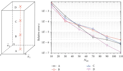
Take the multilayered structure with orthogonal lattices
as an example. The relative error is shown in Figure 4 for
the interpolation of PGF involving a series of interpolation points through the trilinear interpolation method, with
various values of𝑁int. InFigure 4, positions (A, . . . ,D) are
the sampling points for interpolation. A very high level of accuracy is easily obtained with a relatively small number of interpolation points. The side length of the subgrid is usually
fixed to 0.02𝜆, and the higher interpolation accuracy(𝜀 <
10−4)can be obtained.
3. ACA Technique
Let the𝑚 × 𝑛rectangular matrix𝑍𝑚×𝑛represent the coupling
between two well-separated groups in the MoM computation.
The ACA algorithm aims to accurately approximate𝑍𝑚×𝑛by
o B C D A B C D A 10 20 30 40 50 60 70 80 90 100 110 1E − 7 1E − 6 1E − 5 1E − 4 1E − 3 Re la ti ve err o r 𝜀 Nint ⇀ a1 ⇀ a2
Figure 4: The relative error of a series of points. Reference structure: primitive vector|⇀𝑎1| = |⇀𝑎2| = 0.55𝜆,ℎ = 2.2𝜆; phase shifts𝑘𝑥 =
𝑘cos(45∘),𝑘𝑦= 𝑘sin(30∘). Accuracy reached interpolating PGFs through trilinear interpolation, with a 3D grid of𝑁int×𝑁int×2𝑁intequispaced points in−0.55𝜆 < Δ𝑥 <0.55𝜆,−0.55𝜆 < Δ𝑦 <0.55𝜆, 0< Δ𝑧 <2.2𝜆. The data plotted refers to the straight line from(0.15𝜆, 0.15𝜆, 0)to
(0.15𝜆, 0.15𝜆, 2.2𝜆). The number of equally spaced sampling points is 4.
constructs the approximate matrix𝑍̃𝑚×𝑛 through a product
form. Namely, ̃ 𝑍𝑚×𝑛= 𝑈𝑚×𝑟𝑉𝑟×𝑛=∑𝑟 𝑖=1 𝑢𝑖 𝑚×1V𝑛×1𝑖 , (14)
where𝑟is the rank of𝑍̃𝑚×𝑛or the effective rank of the matrix
𝑍𝑚×𝑛; 𝑈𝑚×𝑟 and 𝑉𝑟×𝑛 are two dense rectangular matrices;
𝑢𝑖
𝑚×1 is the column𝑖th of𝑈; andV𝑖𝑛×1 is the row𝑖th of𝑉,
respectively. The goal of ACA is to achieve
𝑍𝑚×𝑛− ̃𝑍𝑚×𝑛𝐹≤ 𝜀 𝑍𝑚×𝑛𝐹 (15)
for a given tolerance𝜀. Note that in this paper‖ ⋅ ‖refers to
the matrix Frobenus norm [9].
The ACA technique is numerically based on the principle of the approximation above but does not need to know
all terms of 𝑍𝑚×𝑛. Indeed, only 𝑟 rows and 𝑟 columns
are calculated during the algorithm allowing a significant reduction in the number of integral computations to perform. Therefore, not only is the memory requirement reduced but the assembly time is also saved. Yet, if we agree to deal with
the MVP𝑈𝑚×𝑟𝑉𝑟×𝑛𝑏𝑛×1instead of the exact value of𝑍𝑚×𝑛𝑏𝑛×1,
the number of operations needed is also remarkably reduced
by performing𝑈𝑚×𝑟(𝑉𝑟×𝑛𝑏𝑛×1). Thus, if an iterative solver is
used, one can accelerate matrix vector multiply and save once
again the computation time [10].
The compression rate 𝜂 of matrix block 𝑍𝑚×𝑛, which
denotes the memory saved by using ACA, can be expressed as
𝜂 (%) = (1−𝑟 ⋅ (𝑚 + 𝑛)
𝑚 ⋅ 𝑛 ) ⋅100%. (16)
Obviously, the approximation by ACA approach above is
use-ful only if𝑟 < (1/2) ⋅min{𝑚, 𝑛}, where𝑍𝑚×𝑛presents similar
values. For the electromagnetic application, the effective rank
𝑟 < min(𝑚, 𝑛). Therefore, instead of storing entire𝑚 × 𝑛
entries, the algorithm only requires storing(𝑚+𝑛)×𝑟entries.
4. Numerical Results
The EFIE and ACA approaches to PEC are implemented using Fortran-95 language. Numerical experiments run on a PC with Intel i5-2400 3.1 GHz CPU and 16 GB RAM. The resulting impedance matrices are iteratively solved by using the transpose-free quasi-minimal residual (TFQMR)
solver with diagonal preconditioning [21]; the relative error
tolerance is set to be 10−3.
4.1. Infinite Metallic Rod. As a 2D example, we study the scattering properties of a photonic band gap (PBG) structure
consisting of infinite metallic rod [17]. Each unit cell consists
of two infinitely long metallic rods. The inset ofFigure 5is
two meshed cylinders in a unit cell. The axis of each cylinder
is along𝑥-direction:⇀𝑎1 = ̂𝑥6 mm and⇀𝑎2 = ̂𝑦6 mm. Each
cylinder has the radius 0.6 mm and length 6 mm. The space between two cylinders is 6 mm. Each cylinder was discretized into 494 triangle facets with 741 unknowns to ensure accurate
results obtained in the entire frequency band.Figure 5shows
the magnitude of the transmission and reflection coefficients
for the Floquet TM00 mode with the electric field oriented
in the𝑥-direction. Our results agree well with the reference
results obtained using 2D IE approach [15]. The results
converged for 9 terms in both Ewald sums and there are 1482 unknowns for the geometry. The time for matrix filling and solving is 0.58 s and 0.21 s per frequency point, respectively.
−50 −40 −30 −20 −10 0 Refl . a n d T ra n s. co efficien ts (dB) Frequency (GHz) Refl. Trans. Refl. [15] o 1 2 Unit cell 10 20 30 40 50 ⇀ a1 ⇀ a2
Figure 5: Reflection and transmission coefficient of two-layer rod PBG. 20 25 30 35 40 45 −80 −60 −40 −20 0 T ra n simissio n (dB) Frequency (GHz) 5-layer 10-layer 21-layer Layer: 1 2 3 N − 1 N .. .
Figure 6: Transmission coefficient of multilayered PBG.
one cylinder. If the trilinear interpolation method is not used, the time of matrix filling would increase dramatically to 128.6 s. Therefore, trilinear interpolation of PGFs can reduce the time of matrix filling by more than 99.5%.
Next, the number of layers increases from 2 to 5, 10 and
21, respectively.Figure 6 shows the transmission coefficient
of multilayered structure. The transmission coefficient curves exhibit the typical resonances of photonic band gap materials. It can be seen that the null of transmission becomes deeper as the layer number increases. The total solution times for per frequency point are 5.1 s, 12.4 s, and 32.5 s, respectively.
The 21-layer structure is meshed into 10374 triangle facets
with 15561 unknowns. The compression rate𝜂of matrix block
is shown inTable 1. The times for matrix filling and matrix
solving are 23.8 s and 8.7 s per frequency point, respectively.
1.0 1.2 1.4 1.6 1.8 2.0 0.0 0.2 0.4 0.6 0.8 1.0 Reflec tio n 4-layer 8-layer 16-layer 16-layer [Ansys HFSS] w d h 𝜆(𝜇m)
Figure 7: Reflection spectra for multilayered woodpile MPC.
Table 1: Compression rate𝜂(%) of matrix block.
𝑍1,1 𝑍1,2 𝑍1,3 𝑍1,4 𝑍1,5 𝑍1,6 𝑍1,7 — 20.78 8.64 5.40 5.94 5.67 4.86 𝑍1,8 𝑍1,9 𝑍1,10 𝑍1,11 𝑍1,12 𝑍1,13 𝑍1,14 6.21 5.67 4.05 3.51 3.78 4.59 4.32 𝑍1,15 𝑍1,16 𝑍1,17 𝑍1,18 𝑍1,19 𝑍1,20 𝑍1,21 4.86 5.40 4.32 3.78 4.05 3.24 3.51
— denotes the matrix block calculated directly by MoM.
The corresponding times of direct solution by MoM without ACA acceleration are 187.6 s and 75.2 s per frequency point, respectively. Obviously, ACA can greatly reduce the total solution time, especially for frequency sweeping.
4.2. Woodpile. A 3D example showing the inset inFigure 7
is a woodpile MPC with𝑤 = 200nm,ℎ = 300nm and
in-layer lattice constant 𝑑 = 1 𝜇m. The incident wave is a
TE polarized (i.e.,𝐸parallel to the top metallic layer) plane
wave through the stacking direction. The number of layers are 4, 8, and 16, respectively. Two intersecting metallic pipes are considered to be fully contacting with each other in
numerical modeling. The ACA box size is 1×1×0.3𝜇m3. The
reflection coefficients are shown inFigure 7. Almost the same
result is obtained for TM polarization. Our numerical results agree well with that of Ansys HFSS. Previous results reported
by other studies [12,22] for a similar kind of the structural
geometry also validate our calculated results. For the 16-layer MPC with 13149 unknowns (8766 triangle facets), the times for matrix filling and linear system solving are 40.3 s and 15.2 s per frequency point, respectively. The corresponding times of direct solution by MoM without ACA acceleration are 132.3 s and 92.5 s, respectively.
5. Conclusion
An integral equation accelerated with adaptive cross approx-imation (ACA) is proposed for the analysis of multilayered metallic photonic crystal. The ACA is a purely algebraic and
kernel independent algorithm. It is verified to be suited for accelerating integral equation analysis of periodic structure. The ACA can be applied to compress impedance matrix blocks and accelerate MVP for reducing computational com-plexity. A modified Ewald transformation and an efficient interpolation method are also proposed to fast compute the periodic Green’s function; hence, that can greatly reduce the time of matrix filling. Numerical results confirm the validity and accuracy of the proposed method. In our next stage of research, ACA will be applied to accelerate hybrid field integral equation for arbitrarily complex multilayered periodic structure composed of metal and dielectric materials with more unknowns.
Conflict of Interests
The authors declare that there is no conflict of interests regarding the publication of this paper.
Acknowledgments
The work was supported in part by the National Science Foundation of China (NSFC) under Grants no. 61331002, no. 61102011, and no. 61201082 and in part by Excellent Innovation Team of CUC under Grant no. yxtd201303.
References
[1] J. D. Joannopoulos, R. D. Meade, and J. N. Winn, Photonic Crystals: Molding the Flow of Light, Princeton University Press, Princeton, NJ, USA, 1995.
[2] R. D. Meade, A. M. Rappe, K. D. Brommer, J. D. Joannopoulos, and O. L. Alerhand, “Accurate theoretical analysis of photonic band-gap materials,”Physical Review B, vol. 48, no. 11, pp. 8434– 8437, 1993.
[3] X. Wang, X.-G. Zhang, Q. Yu, and B. N. Harmon, “Multiple-scattering theory for electro-magnetic waves,”Physical Review B, vol. 47, no. 8, pp. 4161–4167, 1993.
[4] J. B. Pendry, “Photonic structures,”Journal of Modern Optics, vol. 41, pp. 209–229, 1994.
[5] J. A. Roden, S. D. Gedney, M. P. Kesler, J. G. Maloney, and P. H. Harms, “Time-domain analysis of periodic structures at oblique incidence: orthogonal and nonorthogonal FDTD implementations,”IEEE Transactions on Microwave Theory and Techniques, vol. 46, no. 4, pp. 420–427, 1998.
[6] A. A. Tavallaee and J. P. Webb, “Finite-element modeling of evanescent modes in the stopband of periodic structures,”IEEE Transactions on Magnetics, vol. 44, no. 6, pp. 1358–1361, 2008. [7] I. Tsukerman and F. ˇCajko, “Photonic band structure
compu-tation using FLAME,”IEEE Transactions on Magnetics, vol. 44, no. 6, pp. 1382–1385, 2008.
[8] M. Bebendorf, “Approximation of boundary element matrices,”
Numerische Mathematik, vol. 86, no. 4, pp. 565–589, 2000. [9] K. Zhao, M. Vouvakis, and J.-F. Lee, “The adaptive cross
approx-imation algorithm for accelerated method of moments compu-tations of EMC problems,”IEEE Transactions on Electromag-netic Compatibility, vol. 47, no. 4, pp. 763–773, 2005.
[10] A. Heldring, J. M. Tamayo, C. Simon, E. Ubeda, and J. M. Rius, “Sparsified adaptive cross approximation algorithm for acceler-ated method of moments computations,”IEEE Transactions on Antennas and Propagation, vol. 61, no. 1, pp. 240–246, 2013.
[11] M. Sarnowski, T. Vaupel, V. Hansen, E. Kreysa, and H. P. Gemuend, “Characterization of diffraction anomalies in 2-D photonic bandgap structures,”IEEE Transactions on Microwave Theory and Techniques, vol. 49, no. 10, pp. 1868–1872, 2001. [12] S. Y. Lin, G. Arjavalingam, and W. M. Robertson, “Investigation
of absolute photonic bandgaps in 2-dimensional dielectric structures,”Journal of Modern Optics, vol. 41, pp. 385–393, 1994. [13] W. C. Chew, J. M. Jin, E. Michielssen, and J. Song,Fast and Efficient Algorithm in Computational Electromagnetics, chapter 3, Artech House, Boston, Mass, USA, 2001.
[14] S. M. Rao, D. R. Wilton, and A. W. Glisson, “Electromagnetic scattering by surfaces of arbitrary shape,”IEEE Transactions on Antennas and Propagation, vol. 30, no. 3, pp. 409–418, 1982. [15] F.-G. Hu and J. Song, “Integral-equation analysis of scattering
from doubly periodic array of 3-D conducting objects,”IEEE Transactions on Antennas and Propagation, vol. 59, no. 12, pp. 4569–4578, 2011.
[16] M. G. Silveirinha and C. A. Fernandes, “A new acceleration technique with exponential convergence rate to evaluate peri-odic Green functions,” IEEE Transactions on Antennas and Propagation, vol. 53, no. 1, pp. 347–355, 2005.
[17] K. E. Jordan, G. R. Richter, and P. Sheng, “An efficient numerical evaluation of the Green’s function for the Helmholtz operator on periodic structures,”Journal of Computational Physics, vol. 63, no. 1, pp. 222–235, 1986.
[18] R. D. Graglia, “On the numerical integration of the linear shape functions times the 3-D Green’s function or its gradient on a plane triangle,”IEEE Transactions on Antennas and Propagation, vol. 41, no. 10, pp. 1448–1455, 1993.
[19] S. J¨arvenp¨a¨a, M. Taskinen, and P. Yl¨a-Oijala, “Singularity subtraction technique for high-order polynomial vector basis functions on planar triangles,”IEEE Transactions on Antennas and Propagation, vol. 54, no. 1, pp. 42–49, 2006.
[20] J. F. Hughes and A. V. Dam,Computer Graphics: Principles and Practice, Addison-Wesley, 3rd edition, 2013.
[21] Y. Saad, Iterative Methods for Sparse Linear Systems, SIAM Society for Industrial & Applied Mathematics, 2nd edition, 2003.
[22] J. G. Fleming, S.-Y. Lin, I. El-Kady, R. Biswas, and K. M. Ho, “All-metallic three-dimensional photonic crytal with a large infrared bandgap,”Nature, vol. 417, no. 6884, pp. 52–55, 2002.
International Journal of
Aerospace
Engineering
Hindawi Publishing Corporationhttp://www.hindawi.com Volume 2014
Robotics
Journal ofHindawi Publishing Corporation
http://www.hindawi.com Volume 2014
Hindawi Publishing Corporation
http://www.hindawi.com Volume 2014
Active and Passive Electronic Components
Control Science and Engineering Journal of
Hindawi Publishing Corporation
http://www.hindawi.com Volume 2014 Machinery
Hindawi Publishing Corporation
http://www.hindawi.com Volume 2014
Hindawi Publishing Corporation http://www.hindawi.com
Journal of
Engineering
Volume 2014
Submit your manuscripts at
http://www.hindawi.com
VLSI Design
Hindawi Publishing Corporation
http://www.hindawi.com Volume 2014
Hindawi Publishing Corporation
http://www.hindawi.com Volume 2014
Shock and Vibration
Hindawi Publishing Corporation
http://www.hindawi.com Volume 2014
Civil Engineering
Advances inAcoustics and VibrationAdvances in
Hindawi Publishing Corporation
http://www.hindawi.com Volume 2014
Hindawi Publishing Corporation
http://www.hindawi.com Volume 2014
Electrical and Computer Engineering
Journal of
Advances in OptoElectronics
Hindawi Publishing Corporation
http://www.hindawi.com Volume 2014
The Scientific
World Journal
Hindawi Publishing Corporationhttp://www.hindawi.com Volume 2014
Sensors
Journal of Hindawi Publishing Corporationhttp://www.hindawi.com Volume 2014
Modelling & Simulation in Engineering
Hindawi Publishing Corporation
http://www.hindawi.com Volume 2014
Hindawi Publishing Corporation
http://www.hindawi.com Volume 2014 Chemical Engineering
International Journal of Antennas and
Propagation International Journal of
Hindawi Publishing Corporation
http://www.hindawi.com Volume 2014
Hindawi Publishing Corporation
http://www.hindawi.com Volume 2014
Navigation and Observation International Journal of
Hindawi Publishing Corporation
http://www.hindawi.com Volume 2014