Sharif University of Technology
Scientia IranicaTransactions A: Civil Engineering http://scientiairanica.sharif.edu
Research Note
The eect of xed-tip piles on stabilization of earth
slopes
M. Hajiazizi
a;, M. Nasiri
a, and A.R. Mazaheri
ba. Department of Civil Engineering, Razi University, Taq-e Bostan, Kermanshah, Iran. b. Department of Civil Engineering, Ayatollah Boroujerdi University, Boroujerd, Iran. Received 12 October 2016; received in revised form 5 January 2017; accepted 3 July 2017
KEYWORDS Earth slope; Fixed-tip pile; Pile length reduction; Stabilization;
Experimental modeling.
Abstract.A recent widely researched solution is slope stabilization using a row of piles. In this study, the eects of xed-tip pile and the subsequent pile length reduction, which nally bring about a reduction in stabilization costs, were considered. This paper presents novel analyses that were carried out in static condition. The analyses were performed using the Limit Equilibrium (LE) method and Shear Strength Reduction (SSR) method, which approved one another. Fixing pile tip was an ecient and applicable method for stabilizing earth slopes and reducing pile length. Results of these analyses were acceptable and properly consistent with the results obtained by other researchers. The process of xing the end of the pile was also carried out experimentally and a new method was proposed for this purpose that, besides being simple, was cost-eective and practical. The result of this investigation showed the eectiveness of the proposed method, in which xing the pile tip could enhance Factor of Safety (FoS) up to 55%.
© 2018 Sharif University of Technology. All rights reserved.
1. Introduction
Installing piles for stabilizing endangered earth slopes is an eective way for preventing the imbalance of force and instability. Slope stability analysis [1-4] and reinforcing the slopes using piles [5-7] are among the major issues to be addressed in geotechnical engineer-ing.
Stabilization of sliding and imbalanced earth slopes is more complicated and costly. Stabilizing eect by using pile is provided by the passive resistance of the pile below the slip surface and load transfer from the sliding mass to the underlying stationary soil or
*. Corresponding author. Tel./Fax: 08334283264 E-mail addresses: [email protected] (M. Hajiazizi); [email protected] (M. Nasiri); [email protected] (A.R. Mazaheri)
doi: 10.24200/sci.2017.4211
rock formation through the piles due to soil arching mechanism [8-13].
Kourkoulis et al. [14] divided pile-based stabiliza-tion methods for earth slopes into the following two categories:
1. Displacement-or pressure-based methods [15-20];
2. Numerical methods [17,21-23].
Moreover, slope stability and optimizing pile location by installing a row of piles [16,19,24-28] have been studied by many researchers. It is shown that internal friction angle is the most inuential parameter in the slope stability analysis of nite slopes [29]. Kourkoulis et al. [14] developed a hybrid methodology for the design of slope-stabilizing piles. This method combined the rigor of 3D nite element simulation with the simplicity of widely accepted analytical techniques. The piles were embedded in the stable soil by the length of 5D (D = pile diameter), because the zone
of inuence of each pile had been demonstrated not to exceed 5D and the length of the pile was restricted to 10D. Fixing pile end helped to have a pile length shorter than the length proposed by Kourkoulis [14] and diminished stabilization costs.
Ito and Matsui [16] developed a plastic extrusion-deformation model for rigid piles of innite length (not closely spaced) to estimate the shear resistance oered by a row of piles embedded in a slope. Their approach presumed that the soil was soft and deformed plastically around piles. Despite its rigor, the method neglected pile exibility, pile limited length, and soil arching phenomena that might all have a substantial eect [14]. Hassiotis et al. [17] presented the friction circle method by dening new expressions for the stability number to incorporate the pile resistance in slope stability analysis using a closed form solution of the beam equation. The ultimate force intensity (soil-pile pressure) was calculated based on the equations proposed by Ito and Matsui [16] assuming a rigid pile. The Finite Dierence Method (FDM) was used to analyze the pile section below the critical surface as a beam on elastic foundations. However, the safety factor of the slope after inserting the piles was obtained based on the new critical failure surface, which was not necessarily the one before pile installation [30]. Poulos [19] introduced a method of analysis in which a simplied form of boundary element method [31] was employed to study the response of a row of passive piles incorporated in limit equilibrium solutions of slope stability; in these solutions, the pile was modeled as a simple elastic beam and the soil as an elastic continuum [32]. The method evaluated the maximum shear force that each pile could provide based on an assumed input free eld soil movement and computed the associated lateral response of the pile. The pre-scribed soil movements were employed by considering the compatibility of the horizontal movement of the pile and soil at each element. While pile and soil strength and stiness properties were taken into account to obtain soil-pile pressure in this method, group eects, namely, piles spacing, were not considered in the analysis of soil-pile interaction. Poulos [19] proposed a 12-meter pile; such length of reinforcing element would signicantly increase the stabilization costs. Won et al. [33] presented a numerical comparison of predictions by limit equilibrium analysis and 3D numerical analysis for a slope-pile system. The length of pile was consid-ered to be up to the end of embankment without any limitation. Installation of such a pile not only added to the implementation costs, but also made it dicult to choose the appropriate pile length. Ausilio et al. [34] proposed a pile length two times the height of the pile above the slip surface. This proposed length not only was conservative, but also added to stabilization costs. Fixing the pile end using cement grout is
pre-sented in this work for the rst time. The eects of cement grout and cement treatment on soil strength have been investigated by many researchers [35,36].
It is worth mentioning that under reamed piles are better than conventional piles; however, discontinuity of the piles and the surrounding soil is one of their dis-advantages. This defect has been xed in the proposed method (xed pile tip) and a signicant continuity is created between the pile and its surrounding soil. As a result, deformations are less under equal loading.
This paper studies the eect of xed pile tip on factor of safety and pile length reduction by using the LE method and the SSR method in static analysis.
2. Shear Strength Reduction (SSR) method The safety factor of a slip surface is dened as the re-duction factor by which the original soil shear strength parameters should be reduced to make the slope reach the critical failure state [37].
The reduced shear strength parameters, C0 f and
0
f, are given as follows:
C0
f = C
0
FoS; (1)
0
f = arctan
tan 0
FoS
; (2)
where C0 and 0 are the cohesion and internal friction
angle of the soil, respectively; C0
f and 0f are the
mobilized cohesion and internal friction angle of the slope required to attain the state of critical stability, respectively.
There is another denition of the FoS for SSR method by which the load or gravity is increased by a certain factor to bring the slope to the critical failure state [37].
This denition of FoS is exactly the same as that used in limit equilibrium methods and has been adopted in many other studies [8,11,14,38-40]. Herein, FoS can also be understood as the factor by which the soil shear strength parameters are reduced to give rise to incipient failure. According to the kinematic theory of limit analysis, the factor of safety determined by equating the rate of external work to the rate of internal energy dissipation for any kinematically admissible velocity eld is not less than the true solution to slope stability analysis. Thus, the safety factor can be calculated by minimizing FoS with all kinematically admissible failure mechanisms. When a row of piles is inserted in a slope, the additional resistance that each pile can provide depends on the soil strength. It is suggested that the retaining force be calculated with the reduced values of C0 and 0 to get conservative
3. Pile length optimization
Pile length has a considerable eect on slope stabiliza-tion costs. Hence, it is tried to reduce pile length to the extent that it does not signicantly aect the growth of factor of safety. In order to determine the optimal pile length, it is necessary to calculate the factor of safety associated with each of the proposed length values. First, the pile tip is xed based on dierent length val-ues and then, the variations of factor of safety and the pile length are obtained. Finally, a comparison is made between results obtained from xed and free pile ends.
4. Eect of xed pile end on factor of safety and pile displacement
A useful solution to reduce pile length and displace-ment, diminish stabilization costs, and increase factor of safety (especially that of soft soils) is to x pile ends. This new solution is introduced in this paper. It can drastically reduce pile length and displacement, and increase factor of safety. Although implementation of this solution is associated with specic problems, it yields very good results that justify its implementation. Piles with dierent lengths are xed. Then, the shortest pile length is chosen and implementation costs are reduced as a result.
5. Determining the most eective and economical location for pile installation Although increase in factor of safety is known as an objective of pile-based slope stabilization, it is not its only objective, because costs reduction is another denite objective of any project. Therefore, the best location for pile installation is a place that not only gives the required factor of safety, but also provides for determination of the shortest pile length. Choosing such a location reduces costs as well. The location chosen by the described process is known as the most eective location for pile installation. In order to nd the optimal location, the three-dimensional diagram of pile length, pile location, and factor of safety is prepared. The diagram can be used for determining the minimum pile length with the desirable factor of safety.
6. Fixing the pile tip
6.1. Literature review of xing the pile
Fixing the pile tip using cement grout has been pre-sented in this work for the rst time. The eects of cement grout and cement treatment on soil strength were investigated by many researchers [35,36]. Fixing the pile head (not pile tip) was investigated by some researchers [41,42].
6.2. Procedure of xing the pile tip
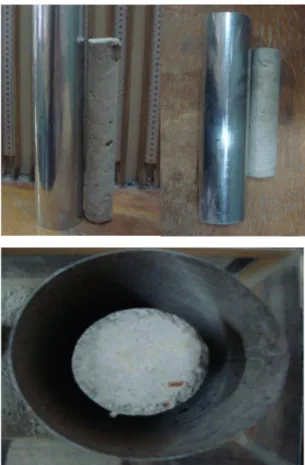
The box used for the tests is shown in Figure 1. In order to construct a xed pile tip in slopes, a new method is presented here, which is described below. To this end, prefabricated pile, a case with larger diameter than pile element and cement slurry, is needed. At rst, the pile is placed at the optimal location in slope and the case is inserted around it (Figure 2); then, the embankment construction around case is performed in
Figure 1. Experimental box and piezometers panel.
Figure 2. Prototype of a pile, a case, and placement of the case around the pile.
multiple steps (the total height of xed end region must be divided into several smaller heights to simplify the process). At the end of each phase, the cement slurry is injected into the surrounding soil through the case. It is worth mentioning that the xing of the pile tip can be implemented in one step. If a larger lateral surface of the pile tip needs to be xed, it is recommended to implement xing operation in several steps and lift the case in each step. For example, in order to x the end of pile with 50 cm diameter up to 3 times its diameter (xed end depth is 150 cm), the steps of construction are divided into 3 phases. At rst, the pile and the case are inserted in the optimal location and the primary 50 cm of soil layer around the case is lled; then, the cement grout is poured into the case. Afterwards, the case is pulled out approximately up to surface layer. By doing this, the cement grout in the case is radially spread and it penetrates in the pile's surrounding soil. Then, the second 50 cm layer is embanked and after completion of lling, the cement slurry is poured into case. Then, the case is removed up to near surface in order to inject cement slurry in the surrounding soil. After the second phase, same as before, the last 50 cm of soil layer is embanked and cement grout is poured in the case. Same as pervious, the case is pulled out and cement slurry is spread into subsoil. By reaching the intended height to create the xed pile tip, the case is completely removed and embankment is performed in ordinary condition. Figure 3 shows the process of constructing a xed pile tip in practice.
Figure 3. Fixed pile tip construction process: (1) inserting the case around the pile; (2) pouring cement slurry into the case; (3) pulling out the case in order to inject the cement grout in subsoil; (4) next phase of pouring cement slurry in the case; (5) next phase of pulling out the case; and (6) nal removal of case and xed-end pile creation after cement grout treatment (brown zone is the integrated area where the pile tip is xed).
This originality in providing xed-tip condition for pile leads to the formation of a rigid and integrated zone around pile end after cement slurry treatment (Figure 4), which causes dramatic increase in resistance against loads in this region.
In order to reach certainty about xed-end pile performance, two experimental tests were carried out in sandy slopes; the rst one was a slope reinforced with free-end pile and the second one was reinforced slope in presence of xed-end pile constructed by this approach.
In the rst model, a prefabricated pile with the diameter of 3.6 cm was placed in the middle of slope and embankment was constructed. Then, after precipitation, loading process began; the critical failure stress was obtained at 10.66 kPa.
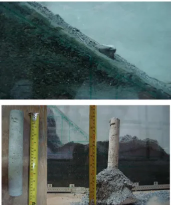
Figure 4. Fixed pile tip construction after the cement slurry treatment proposed in this paper.
In the second model, slope geometry, and soil and pile properties were the same as those in the rst model and a case with the diameter of 5.5 cm was used for provision of xed-end condition. The purpose was to create a xed pile tip with the height of three times the pile diameter (10.8 cm). In order to do that, embankment layers were applied in three phases (each step with embankment height of 3.6 cm). The rst layer was embanked and cement slurry was poured into case. Then, the second step of embankment construction was performed. After the end of the second phase, the case was pulled out about 3 cm in order to inject the cement slurry through surrounding soil. Then, the next step of cement grout purring was carried out. These cycles were repeated until reaching the nal height of xity (10.8 cm) in the end of pile. Then, the case was completely removed and, same as in the construction of the free tip pile, the remaining parts of slope were constructed. After precipitation, loading process was began; in this condition, the critical failure stress was obtained at 19.85 kPa (Figure 5).
The results indicate that by using the simple and eective method proposed in this paper, the pile end can be xed and, due to that, bearing capacity and stability of slope signicantly increase. Comparing these two experimental tests conrmed the eectiveness of xed-tip pile. Moreover, construction procedures of this reinforcing model were simple to execute.
Variations of loading with displacement of pile head for free-end and xed-end piles are shown in
Figure 5. Fixed pile tip in an earth slope (critical stress = 19.85 kPa).
Figure 6. Variations of loading with displacement of pile head for free-end pile.
Figure 7. Variations of loading with displacement of pile head for xed-end pile.
Figures 6 and 7, respectively. Also, variations of loading with time for xed-end pile are shown in Figure 8.
7. Numerical examples 7.1. Example 1
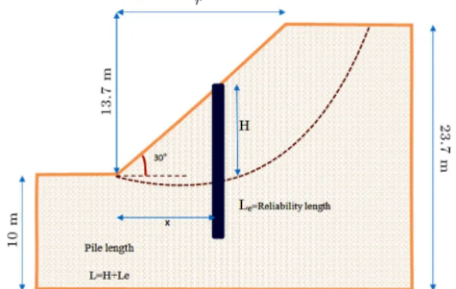
The inclined surface studied in this example is depicted in Figure 9. The embankment height is equal to 13.7 m and its slope is 30 degrees. The unit weight is 19.63 kN/m3, angle of friction is 10 degrees, cohesion
is equal to 23.94 kN/m2, modulus of elasticity is
12000 kN/m2, and Poisson's ratio is 0.3.
7.1.1. Analysis of the eect of xed-tip pile
The xed pile ends method, which is introduced as a new method in this paper, can considerably change the value of the factor of safety. In two- or multi-layer slopes, whose lowest layer has a proper density, the adequate reliability can be obtained by embedding the pile end in the dense layer. However, in the case of homogenous slopes, other methods proposed by some other researchers can be used for reliability purposes. Lee et al. [42] suggested that, in order to achieve the
Figure 8. Variations of loading with time for xed-end pile.
Figure 9. Slope geometry in Example 1 and pile reliability length (Le) under critical slip surface.
reliability length (Le), the pile should be embedded in
the layer below the critical slip surface to a depth equal to H (distance between the critical failure surface and the ground surface).
Kourkoulis et al. [14] believed that the pile reli-ability length (Le) could be 5D at most. Reese and
Van [30] also indicated that the eective zone on each pile beneath the critical slip surface did not exceed 5D. In Figure 10, the critical slip surface for LE and SSR methods is shown. Figure 11 shows the comparison of the results of the SSR method used for free-end and xed-end piles with a length of L = 1:5H. As seen in this gure, xing pile end has a signicant eect on the growth of the factor of safety. A xed pile end can increase the value of the factor of safety up to 55%.
Figure 12 shows the comparison between the results obtained by the SSR method for a row of piles with a length of 1:5H and the results obtained for a row of free-end piles with a length of 2H in [25]. As seen in this gure, in spite of the short length of the pile, xing the pile end has led to a considerable increase in the value of factor of safety. Hence, by diminishing the pile length and adding to the factor
Figure 10. Critical slip surface in LE method (yellow line) and SSR method (red line).
Figure 11. Comparison of the results of the SSR method for xed-end and free-end for L = 1:5H.
Figure 12. Comparison of SSR method for xed-end pile condition with a length of 1:5H and reference [25] with a length of 2H.
Table 1. Variations of pile reliability length and factor of safety for free-tip and xed-tip.
Length of pile(L)
FoS for free-tip
FoS for xed-tip
Percentage of change
H + 1D 1.07 1.69 58%
H + 2D 1.08 1.68 55%
H + 3D 1.09 1.69 55%
H + 4D 1.1 1.7 54%
H + 5D 1.11 1.7 54%
of safety, one of the main objectives of stabilization, i.e., cost reduction, is achieved. As seen in Figure 12, the maximum factor of safety belongs to the piles that are installed in the middle of the slope. In Figure 12, which shows that the highest factor of safety belongs to
x
r = 0:5, variations of the reliability length (Le) below
the critical slip surface are examined in proportion to the factor of safety values. At each phase, the pile reliability length (Le) is increased by 1 D. Table 1
presents the variations of pile reliability length and factor of safety.
As seen in Table 1, in the case of a xed-end pile, increase in Le does not signicantly contribute
to the increase in the factor of safety value. Due to implementation reasons, it is necessary to have a pile reliability length that makes it possible to embed the pile in a depth two times the pile diameter in the layer below the critical slip surface to ensure that the slip band will be above reliability length of the end of pile. 7.1.2. Determining the most eective location for pile
installation
The most eective location for pile installation is the place that not only gives the required factor of safety, but also uses the minimum pile length. As it was described, the factor of safety in a homogenous soil can be signicantly increased by xing the pile end and reducing its length. Although the process of xing pile end is time-consuming and requires precision, the resulting signicant increase in factor of safety and reduction in stabilization costs are the reasons that justify it. As seen in Figures 13 and 14, a horizontal plane can give the required factor of safety. The point that the plane collides with the curve gives the coordinates of dierent pile lengths and locations. The place with the shortest pile length is the most eective for pile installation.
7.2. Example 2
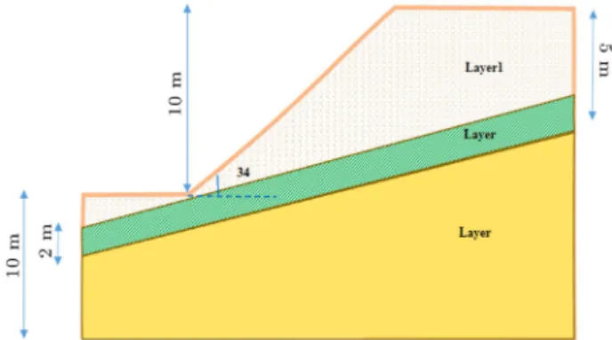
The three-layer earth slope studied in this example is depicted in Figure 15. The strength parameters of the third layer are larger than those of the other two layers. The slope height is 10 m and its angle is 34 degrees. The physical characteristics of the layers are presented in Table 2. The gures of numerical analyses using SLOPW and FDM programs are shown
Figure 13. Three-dimensional diagram of free-end pile length (L), pile location (x=r), and Factor of Safety (FoS) in Example 1.
Figure 14. Three-dimensional diagram of xed-end pile length (L), pile location (x=r), and Factor of Safety (FoS) in Example 1.
Figure 15. Three-layer earth slope geometry in Example 2.
in Figure 16. The minimum factors of safety for LE and SSR methods are calculated at 0.88 and 0.75, respectively.
7.2.1. Analysis of the eect of xed pile tip
In this example, the third layer, which lies at the bottom of the pile, has the largest strength parameters. Figure 17 shows the results of modeling a pile for
Table 2. Shear strength parameters of earth slope in Example 2. Layer
no.
Cohesion (kPa)
Friction angle (degree)
Unit weight (kN/m3)
Poisson's ratio
Elasticity modulus (kN/m2)
Layer 1 29.4 12 18.8 0.3 12000
Layer 2 9.8 5 18.8 0.3 12000
Layer 3 29.4 40 18.8 0.3 12000
Figure 16. Numerical analysis for Example 2: (a) SLOPEW, and (b) FDM softwares.
Figure 17. Comparison of LE and SSR methods for dierent locations and L = 1:5H in free-end and xed-end conditions.
dierent locations (0:1 x=r 0:8) and L = 1:5H in free-end and xed-end conditions.
As seen in Figure 17, xing the pile end does not
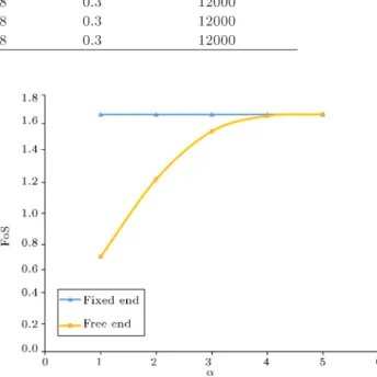
Figure 18. Variations of pile reliability length (Le= D) and FoS for the xed-end and free-end piles.
leave a signicant eect on the value of factor of safety. The reason is that emplacing the pile end into a layer with large strength parameters is the same as xing the pile end. As seen in Figure 17, at x
r = 0:1, the results
obtained for xed-end pile do not very well comply with the results of the free-end pile. The reason is that the length required for emplacing the pile end into the third layer is not achieved.
Figure 17 indicates that the largest factor of safety belongs to x
r = 0:4. Hence, the variations of reliability
length (Le) are studied based on the factor of safety
of x
r = 0:4. Results of the variations of reliability
length (Le) are depicted in Figure 18. As seen in this
gure, in the case of the xed-end pile, increase in the reliability length does not have a signicant eect on the increase in the factor of safety. However, in the case of the free-end pile, increase in the pile length leads to the growth of safety factor. The maximum factor of safety is also achieved with L = H + 4D and with length values higher than H + 4D, the factor of safety remains unchanged. The increase in the factor of safety is a result of the collision between pile end and the dense layer. A comparison between Figures 15 and 16 indicates that to achieve a safety factor of 1.2 for a free pile tip, it is necessary to choose a pile with a length 5D longer than the xed pile tip. If the pile diameter is considered 1 meter, the volume of reinforced concrete will be increased by about 4 cubic meters. Given that implementation of concrete per cubic meter costs 20 dollars, 80 extra dollars will be needed for each pile.
Thus, 10 piles in a row will cause 800 dollars extra costs.
7.2.2. Determining the most eective and economical location for pile installation
As it was explained earlier, if the pile end is embed-ded in a strong layer, xing the pile end will not signicantly increase the factor of safety (except for the pile end that is xed in the vicinity of slope toe). According to Figure 17, the safety factor for
x
r = 0:4 is equal to 1.67. Figures 19 and 20 show
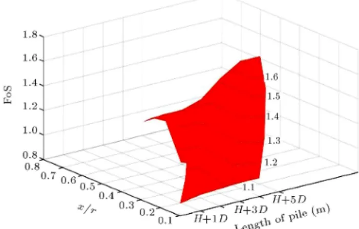
the three-dimensional diagram of pile length (L), pile location (x=r), and factor of safety for free-end and xed-end piles, respectively. In order to nd the most eective location for pile installation, the horizontal plane for the factor of safety of interest should be mapped. The most eective location is the one that requires the shortest pile length. In fact, the most eective location not only yields the required factor
Figure 19. Three-dimensional diagram of pile length (L), pile location (x=r), and Factor of Safety (FoS) for free-end pile.
Figure 20. Three-dimensional diagram of pile length (L), pile location (x=r), and Factor of Safety (FoS) for
xed-end pile.
of safety, but also provides for the determination of the shortest pile length and reduction in stabilization costs.
8. Conclusion
In this paper, the minimum stabilization pile length was achieved by a new proper method. Fixing pile tip was a method that helped to reduce stabilization costs. Then, the most eective location that required the shortest length was found by mapping the three-dimensional diagram of pile length, pile location, and factor of safety. In order to obtain the maximum factor of safety for a row of free-end piles in homogenous slopes, the piles should be placed near slope crown or in the middle of the slope. If the piles are installed in inappropriate location with inadequate length, the factor of safety decreases, instead of increasing.
Fixing pile tips in homogenous slopes could in-crease factor of safety by up to 55%. As a result, pile length and stabilization costs would be reduced. It should be mentioned that xing pile tips should be done with adequate care. If the end of a pile in a non-homogeneous slope is emplaced into a dense layer, the required reliability length will be achieved. In such cases, xing pile tip will not signicantly increase the factor of safety. However, if the pile tip is embedded into soft layer, xing pile tips can increase the safety factor by up to 55%.
References
1. Hajiazizi, M., Kilanehei, P., and Kilanehei, F. \A new method for three dimensional stability analysis of earth slopes", Scientia Iranica, 25(1), pp. 129-139 (2018).
2. Ghanbari, E. and Hamidi, A. \Stability analysis of dry sandy slopes adjacent to dynamic compaction process", Scientia Iranica, 24(1), pp. 82-95 (2017).
3. Zhang, G. and Wang, L. \Integrated analysis of a coupled mechanism for the failure processes of pile-reinforced slopes", Acta Geotechnica, 11(4), pp. 941-952 (2016).
4. Wang, L. and Zhang, G. \Progressive failure behavior of pile-reinforced clay slopes under surface load con-ditions", Environmental Earth Sciences, 71(12), pp. 5007-5016 (2014).
5. Xu, J. and Niu, F. \Safety factor calculation of soil slope reinforced with piles based on Hill's model theory", Environmental Earth Sciences, 71(8), pp. 3423-3428 (2014).
6. Xiao, S. \A simplied approach for stability analysis of slopes reinforced with one row of embedded stabi-lizing piles", Bulletin of Engineering Geology and the Environment, pp. 1-12 (2016).
7. Chen, C., Xia, Y., B, V.M. \Slope stability analysis by polar slice method in rotational failure mechanism", Computers and Geotechnics, 81, pp. 188-194 (2017).
8. Chen, L.T., Poulos, H.G., and Hull, T.S. \Model tests on pile groups subjected to lateral soil movement", Soils and Foundation, 37(1), pp. 1-12 (1997).
9. Chen, C.Y. and Martin, G.R. \Soil-structure inter-action for landslide stabilizing piles", Computers and Geotechnics, 29(5), pp. 363-386 (2002).
10. Liang, R. and Zeng, S. \Numerical study of soil arching mechanism in drilled shafts for slope stabilization", Soils and Foundations, 42(2), pp. 83-92 (2002).
11. Verveckaite, N., Amsiejus, J., and Stragys, V. \Stress-strain analysis in the soil sample during laboratory testing", J. of Civil Engineering and Management, 13(1), pp. 63-70 (2007).
12. Kahyaoglu, M.R., Imancli, G., Ozturk, A.U., and Kayalar, A.S. \Computational 3D nite element anal-yses of model passive piles", Computational Materials Science, 46(1), pp. 193-202 (2009).
13. Kahyaoglu, M.R., Onal, O., Imancl, G., Ozden, G., and Kayalar, A.S. \Soil arching and load transfer mechanism for slope stabilized with piles", J. of Civil Engineering and Management, 18(5), pp. 701-708 (2012).
14. Kourkoulis, R., Gelagoti F., Anastasopoulos I., and Gazetas, G. \Hybrid method for analysis and design of slope stabilizing piles", J. of Geotechnical and Geoen-vironmental Engineering, 138(1), pp. 1-14 (2012).
15. De Beer, E.E. and Wallays, M. \Forces induced in piles by unsymmetrical surcharges on the soil round the piles", Conf. on Soil Mechanics and Foundation Engineering, 1, Spanish Society for Soil Mechanics and Foundations, Madrid, Spain, pp. 325-332 (1972).
16. Ito, T. and Matsui, T. \Methods to estimate lateral force acting on stabilizing piles", Soils and Founda-tions, 15(4), pp. 43-60 (1975).
17. Hassiotis, S., Chameau, J.L., and Gunaratne, M. \Design method for stabilization of slopes with piles", Geotech. Geoenviron. Eng., 123(4), pp. 314-323 (1997).
18. Chen, L.T., Poulos, H.G., and Hull, T.S. \Model tests on pile groups subjected to lateral soil movement", Soils and Foundation, 37(1), pp. 1-12 (1997).
19. Poulos, H.G. \Design of reinforcing piles to increase slope stability", Can Geotech J., 32(5) pp. 808-818 (1995).
20. Tschebotario, G.P., Foundations, Retaining and Earth Structures, McGraw Hill, New York (1973).
21. Fakhimi, A., Continuum Analysis 2-Dimensional-Theory and User's Manual, BHRC Publication, Iran (2001).
22. Poulos, H.G. and Chen, L.T. \Pile response due to excavation induced lateral soil movement", Geotech. Geoenviron. Eng., 123(2), pp. 94-99 (1997).
23. Goh, A.T.C., The, C.I., and Wong, K.S. \Analysis of piles subjected to embankment induced lateral soil movements", Geotech. Geoenviron. Eng., 123(4), pp. 312-323 (1997).
24. Hajiazizi, M. and Mazaheri, A.R. \Use of line segments slip surface for optimized design of piles in stabiliza-tion of earth slopes", Internastabiliza-tional Journal of Civil Engineering, Geotechnical Engineering, 13(1), pp. 14-27 (2015).
25. Li, X., Pei, X., Gutierrez, M., and He, S. \Optimal lo-cation of piles in slope stabilization by limit analysis", Acta Geotechnica, 7(3), pp. 253-259 (2012).
26. Hassiotis, S., Chameau, J.L. and Gunaratne, M. \Design method for stabilization of slopes with piles", Geotech. Geoenviron. Eng. ASCE, 123(4), pp. 314-323 (1997).
27. Poulos, H.G. \Design of slope stabilizing piles", Slope Stability Engineering, N. Yagi, T. Yamagami, and J.C. Jiang, Eds., A. A. Balkema, Rotterdam, Netherlands (1999).
28. Reese, L.C., Wang, S.T., and Fouse, J.L. \Use of drilled shafts in stabilizing a slope", Proc., Specialty Conf. on Stability and Performance of Slopes and Embankments II (GSP 31), 2, ASCE, New York, pp. 1318-1332 (1992).
29. Johari, A., Mousavi, S., and Hooshmand Nejad, A. \A seismic slope stability probabilistic model on Bishop's method using analytical approach", Scientia Iranica, 22(3), pp. 728-741 (2015).
30. Reese, L.C. and Van Impe, W.F. \Single piles and pile groups under lateral loading", A. Balkema, Rotterdam, Netherlands (2001).
31. Poulos, H.G. \Analysis of piles in soil undergoing lateral movement", Soil Mech. Found. Div ASCE, 99(5), pp. 391-406 (1973).
32. Ashour, M. and Ardalan, H. \Analysis of pile stabilized slopes based on soil-pile interaction", Computers and Geotechnics, 39, pp. 85-97 (2012).
33. Won, J., You, K., Jeong, S., and Kim, S. \Coupled eects in stability analysis of pile-slope systems", Computers and Geotechnics, 32, pp. 304-315 (2005).
34. Ausilio, E., Conte, E., and Dente, G. \Stability analysis of slopes reinforced with piles", Computers and Geotechnics, 28, pp. 591-611 (2001).
35. Ebadi, M., Habibagahi, G., and Hataf, N. \Eect of cement treatment on soil non-woven geotextile interface", Scientia Iranica A, 22(1), pp. 69-80 (2015).
36. Yildiz, M. and Soganci, A.S. \Improvement of the strength of soils which comprises granular pumice by injection of cement under low pressure", J. Scientia Iranica A, 22(1), pp. 81-91 (2015).
37. Wei, W.B. \Three dimensional slope stability analysis and failure mechanism", Ph.D. Thesis, Hong Kong Polytechnic University, Hong Kong (2008).
38. Wang, M.C., Wu, A.H., and Scheessele, D.J. \Stress and deformation in single piles due to lateral movement of surrounding soils", Behavior of Deep Foundations: ASTM Special Technical Publication, 670, Raymond Lunggren, Ed., ASTM, West Conshohocken, PA, pp. 578-591 (1979).
39. Popescu, M.E. \Landslide control by means of a row of piles", Slope Stability Engineering: Proc., Int. Conf. on Slope Stability, Thomas Telford, London, pp. 389-394 (1991).
40. Li, X., Pei, X., Gutierrez, M., and He, S. \Optimal lo-cation of piles in slope stabilization by limit analysis", Acta Geotechnica, 7, pp. 253-259 (2012).
41. Papadopolou, M.C. and Comodromos, E.M. \On the response prediction of horizontally loaded xed-head pile groups in sands", Computers and Geotechnics, 37, pp. 930-941 (2010).
42. Lee, C.Y., Hull, T.S., and Poulos, H.G. \Simplied pile-slope stability analysis", Computers and Geotech-nics, 17, pp. 1-16 (1995).
Biographies
Mohammad Hajiazizi is Associate Professor of Geotechnical Engineering at Razi University, Kerman-shah, Iran. He received his PhD degree in Geotechnical Engineering from Shiraz University under the
Supervi-sion of Professors A. Ghahramani and Hataf and his MSc degree in Geotechnical Engineering from Tarbiat Modarres University under the supervision of Professor A. Fakhimi. His current and main research interests are soil improvement, slope stability, tunneling, and meshless methods.
Mosoud Nasiri is PhD candidate in Geotechnical Engineering at Razi University, Kermanshah, Iran. He received his MSc degree in Geotechnical Engineering from Razi University under the supervision of Dr. M. Hajiazizi.
Ahmad Reza Mazaheri is Assistant Professor of Geotechnical Engineering at Ayatollah Borujerdi Uni-versity. He received his PhD degree in Geotechnical Engineering from Razi University under the super-vision of Dr. M. Hajiazizi and his MSc degree in Geotechnical Engineering from Amirkabir University of Technology. His current and main research interests are slope stability and soil improvement.