UTILIZING FUNCTIONALIZATION TO ACCESS ADVANCED MATERIALS PROPERTIES
Anne-Martine S. Jackson
A dissertation submitted to the faculty of the University of North Carolina at Chapel Hill in partial fulfillment of the requirements for the degree of Doctor of Philosophy
in the Department of Chemistry
Chapel Hill 2014
Approved By: Valerie S. Ashby Sergei S. Sheiko Wei You
© 2014
ABSTRACT
Anne-Martine S. Jackson: Utilizing Functionalization to Access Advanced Materials Properties
(Under the direction of Valerie S. Ashby)
While there are many materials that can perform a single selected task very well, there is a growing need for smart materials to advance technology in a variety of fields. Smart materials are often inspired by complex biological systems, and thus need to respond to external stimuli and perform multiple functions. It is desired that these materials have the ability to respond to changes in temperature, pressure, pH, light, magnetic field and the presence of other chemicals. A few of the functions that these materials are to perform include sensing, actuating, self-healing, recognition, self-cleaning, and optical switching. To produce materials with the range of tasks that are needed, new and elegant ways to integrate functionality into polymeric systems are needed.
of a material and the functions that it can perform are highly dependent on structure and the molecular functionality of the polymer.
ACKNOWLEDGEMENTS
I would first like to thank my advisor, Valerie, for her support and dedication to my education and future. Along the way, I have gotten a lot of help and had many thoughtful conversations with the members of my research group, and most especially Jason Rochette, Sarah Brosnan, Sara Turner and Katie Houston. In relation to the work in Chapter I, I would like to thank MIRT for funding (NSF DMR-1122483). In addition, I would like to thank Dr. Carrie Donley at CHANL for performing XPS, and Saadya Averick and Antonia Simakova at Carnegie Mellon University for their assistance in learning ARGET ATRP. The work presented in Chapter II was supported by NSF DMR-1206957. I would like to thank the two undergraduate researchers I had the pleasure of working with, Hung Nguyen and Daniel Liauw, for their hard work on the synthetic aspects of this project. The BRIC at UNC performed the CT scans to image the bone cements, and Dr. Amar Kumbhar at CHANL did EDS on the particles. For the work in Chapter III, I would first like to thank Eastman Chemical for providing funding and materials. I would also like to thank the hard work of Katie Houston for assisting with film processing and tensile testing, and Theo Dingemans for imparting some of his vast knowledge of synthesis and processing of aromatic materials.
TABLE OF CONTENTS
LIST OF TABLES ... x
LIST OF FIGURES ... xi
LIST OF ABBREVIATIONS ... xiii
CHAPTER I: GRAFTING POLY(OEGMA) BRUSHES FROM A SHAPE MEMORY ELASTOMER AND SUBSEQUENT WRINKLING BEHAVIOR 1.1Introduction ... 1
1.2Experimental Methods ... 3
1.2.1 Materials ... 3
1.2.2 Monomer and Polymer Characterization ... 4
1.2.3 Film Characterization ... 4
1.2.4 Monomer and Prepolymer Synthesis ... 4
1.2.5 Film Formation via Crosslinking ... 6
1.2.6 Shape Programming and “Click” of ATRP Initiator... 6
1.2.7 Kinetic Study of Aqueous ARGET ATRP ... 7
1.2.8 Grafting-from Shape Memory Surfaces ... 7
1.3Results and Discussion ... 9
1.3.1 Shape Memory Substrates ... 9
1.3.2 “Grafting-from” via Aqueous ARGET ATRP ... 11
1.3.3 Surface Morphology and Wrinkling Behavior ... 14
1.4Conclusions ... 19
CHAPTER II: SOLUTION AND HETEROGENOUS POLYMERIZATION OF IODINE-CONTAINING METHACRYLATE COPOLYMERS FOR BIOMATERIAL APPLICATIONS
2.1 Introduction ... 23
2.2 Experimental Methods... 25
2.2.1 Materials ... 25
2.2.2 Monomer and Polymer Characterization ... 25
2.2.3 Microsphere Characterization ... 26
2.2.4 Bone Cement Characterization ... 26
2.2.5 Preparation of Monomer ... 27
2.2.6 Preparation of Microspheres by Solvent Evaporation ... 27
2.2.7 Suspension Polymerization of Copolymers ... 28
2.2.8 Preparation of Bone Cement ... 29
2.3 Results and Discussion ... 29
2.3.1 Iodinated Monomer Preparation ... 29
2.3.2 Solution Polymerization of Copolymers ... 30
2.3.3 Fabrication of Microbeads by Solvent Evaporation ... 34
2.3.4 Suspension Polymerization of Copolymers ... 35
2.3.4.1 Molecular Weight and Bead Diameter ... 36
2.3.4.2 Reaction Kinetics ... 39
2.3.4.3 Iodine Content ... 40
2.3.5 Bone Cement Characterization ... 41
2.3.5.1 Radiopacity ... 41
References ... 45
CHAPTER III: ENDGROUP FUNCTIONALIZATION OF POLY(ETHYLENE TEREPHALATE) DERIVATIVES WITH UREIDOPYRIMIDIDONE 3.1 Introduction ... 47
3.2 Experimental Methods... 51
3.2.1 Materials ... 51
3.2.2 Polymer Characterization ... 52
3.2.3 Film and Solution Characterization ... 52
3.2.4 PETG Modification ... 52
3.2.5 Solution Film Casting ... 53
3.2.5.1 Filtering ... 53
3.2.5.2 Centrifugation ... 54
3.2.6 Tensile Testing ... 54
3.2.7 Viscosity Testing ... 54
3.3 Results and Discussion ... 55
3.3.1 Endgroup Modification ... 55
3.3.2 Chemical Characterization ... 55
3.3.3 Molecular Weight ... 57
3.3.4 Thermal Degradation ... 58
3.3.5 Thermal Transitions ... 60
3.3.6 Viscosity ... 63
3.3.7 Film Formation and Tensile Testing ... 64
3.4 Conclusions and Outlook ... 68
LIST OF TABLES
Table 2.1: Compositions and Molecular Weights of Copolymers
Synthesized in Toluene at 70 °C ... 32
Table 2.2: Thermal Degradation Temperatures of Polymers Prepared by Solvent Polymerization ... 33
Table 2.3: Diameter of Microspheres Prepared by Solvent Evaporation ... 35
Table 2.4: Molecular Weight of PMMA and P(MMA-IMMA) Copolymer Beads by Suspension Polymerization ... 38
Table 2.5: Bead Size of PMMA and P(MMA-IMMA) Copolymer Beads by Suspension Polymerization ... 38
Table 2.6: Thermal Degradation and Glass Transitions for PMMA and P(MMA-IMMA) Copolymer Beads ... 39
Table 2.7: Compression Modulus of Bone Cements ... 43
Table 3.1: Molecular Weights of PETG and PETG-UPy Polymers ... 58
Table 3.2: Thermal Degradation of PETG and PETG-UPy Polymers ... 60
Table 3.3: Glass Transition Temperatures of PETG and PETG-UPy Polymers ... 61
Table 3.4: Glass Transition Temperatures and Storage Moduli of PETG and PETG-UPy Films ... 66
LIST OF FIGURES Scheme 1.1: Schematic for the fabrication of wrinkled
substrates ... 8
Figure 1.1: ATR-FTIR and XPS of azide, clicked, grafted and control substrates ... 11
Figure 1.2: Molecular weight and conversion of polymers in solution ... 12
Figure 1.3: Static water contact angle for azide, clicked, grafted and control substrates in the secondary shapes ... 14
Figure 1.4: SEMs of grafted substrates varying equilibration time, t1 ... 15
Figure 1.5: Swelling of the clicked substrates in the ARGET reaction solution ... 16
Figure 1.6: SEMs of ungrafted and grafted substrates varying reaction time, t2 ... 18
Scheme 2.1: Synthesis of IMMA monomer ... 30
Scheme 2.2: The limited susceptibility of IMMA to various reactions ... 30
Scheme 2.3: Solution copolymerization of IMMA with MMA. ... 31
Figure 2.1: Polymer composition synthesized by solution polymerization ... 32
Figure 2.2: SEM images of microspheres fabricated by solvent evaporation ... 34
Scheme 2.4: Suspension polymerization of P(MMA-IMMA) copolymers ... 36
Figure 2.3: SEM images of microspheres fabricated by suspension polymerization ... 36
Figure 2.4: Experimental Mn of the suspension polymerization of copolymers ... 37
of MMA and IMMA ... 40
Figure 2.7: Radiopacity of PMMA, P(MMA-co-IMMA6.9) copolymer and 10 wt% BaSO4 bone cements ... 42
Scheme 3.1: The dimerization of two UPy functionalities ... 48
Scheme 3.2: Reaction of PETG polymers with UPy functionality ... 55
Figure 3.1: 1H NMR in CDCl3 of PETG and UPy-functionalized PETG ... 56
Figure 3.2: The ATR-FTIR of the PETG2K, PETG2K-UPy and UPy endgroup ... 57
Figure 3.3: GPC traces of PETG and PETG-UPy ... 58
Figure 3.4: TGA traces of PETG and PETG-UPy ... 59
Figure 3.5: DSC traces of PETG6.8K-UPy and PETG3.8K-UPy after heating to 120 °C ... 62
Figure 3.6: DSC traces of PETG2K-UPy, PETG3.8K-UPy and PETG6.8K-UPy after heating the films to 190 °C ... 63
Figure 3.7: Viscosity of 2.5-12.5 wt% solutions in 1,3,5-trichlorobenzene of PETG6.8K and PETG6.8K-UPy ... 64
Figure S1: 1H NMR of 3-iodo-2,2-bis(iodomethyl)propanol in CDCl3. ... 72
Figure S2: 1H NMR of 3-iodo-2,2-bis(iodomethyl)propyl methacrylate (IMMA) in CDCl3 ... 73
LIST OF ABBREVIATIONS
AIBN azobisisobutyronitrile
ARGET activators regenerated by electron transfer
ATR-FTIR attenuated total reflectance Fourier transform spectroscopy
ATRP atom transfer radical polymerization
BaSO4 barium (II) sulfate
BPO benzoyl peroxide
CDCl3 chloroform-d
CH2Cl2 methylene chloride
CH3CN acetonitrile
CHCl3 chloroform
CHDM cyclohexanedimethanol
CT X-ray computed tomography
CuBr2 copper (II) bromide
CuSO4Ÿ5H2O copper (II) sulfate pentahydrate
DBTDL dibutyltin dilaurate
DMA dynamic mechanical analysis
DMF dimethylformamide
DMPT N,N-dimethyl-p-toluidine
DSC differential scanning calorimetry
E' tensile storage modulus
EDS electron dispersion spectroscopy
fIMMA feed ratio of IMMA
FIMMA copolymer ratio of IMMA
fMMA feed ratio of MMA
FMMA copolymer ratio of MMA
GPC gel permeation chromatography
H2O water
HU Hounsfield units
IMMA 3-iodo-2,2-bis(iodomethyl)propyl methacrylate
Kassoc association constant
MeOH methanol
MIS
2(6-isocyanatohexylaminocarbonylamino)-6-methyl-4[1H]pyrimidinone
MMA methyl methacrylate
Mn number-average molecular weight
Mw weight-average molecular weight
MW molecular weight
NMR nuclear magnetic resonance spectroscopy
OEGMA oligo(ethylene glycol) methacrylate
PBIB propargyl 2-bromoisobutyrl
PBT poly(butylene terephthalate)
PDI polydispersity index
PDMS poly(dimethylsiloxane)
PEGiBBr poly(ethylene glycol) isobutyrylbromide
PET poly(ethylene terephthalate)
PETG glycol-modified poly(ethylene terephthalate)
PETG-UPy Upy-functionalized PETG
PIT poly(butylene isophthalate)
PMMA poly(methyl methacrylate)
Poly(ODA-co-OA) poly(octylene diazoadipate-co-octylene adipate)
SDS sodium dilaurel sulfate
SEM scanning electron microscopy
Sn(Oct)2 tin octanoate
Tg glass transition temperature
TGA thermogravimetric analysis
THF tetrahydrofuran
Tm melting temperature
TPMA tris[(2-pyridyl)-methyl]amine
UPy ureidopyrimidinone
UV ultraviolet
XPS X-ray photoelectron spectroscopy
Chapter I
GRAFTING POLY(OEGMA) BRUSHES FROM A SHAPE MEMORY ELASTOMER AND SUBSEQUENT WRINKLING BEHAVIOR
1.1Introduction
Wrinkles have long been considered undesirable in many materials applications, but recent attention has focused on utilizing wrinkling and other surface instabilities to control surface topography.1,2 Wrinkling can create regular and repeatable surface topographies on multiple length scales, an ability accessible previously only by lithography and micromachining.3 Wrinkled substrates have the potential for practical use as superhydrophobic surfaces,4 dry adhesives,5,6 optical materials,7,8 anti---biofouling coatings,9 microfluidic devices10 and flexible electronics.11 The simplicity in which wrinkled materials can be fabricated makes them attractive for applications that require large---scale fabrication of uniformly patterned surfaces.12
anisotropic mechanical properties due to finite extensibility of brush chains perpendicular to the substrate caused by in---plane steric repulsion.19 Other advantages of polymer brushes over solid layers is that they are covalently bound to the substrate and thus resist delamination and cracking, and a large number of functional monomers can be polymerized by a variety of controlled surface---initiated polymerizations and thus impart chemical functionality to the surface.20
While growing polymer brushes from static substrates is well studied, growing polymer brushes from elastomeric substrates is less frequently examined, and there are only a few studies of wrinkling in elastomer---brush bilayer systems. In one example, Stafford et al. found they could use surface wrinkling to characterize the height and modulus of poly(methyl methacrylate) brushes grown from a post--- functionalized poly(dimethylsiloxane) (PDMS) substrate.18 In a second example, poly(2---hydroxyethyl methacrylate) and poly(oligo ethylene glycol methacrylate) (poly(OEGMA)) brushes were grown from a bulk functionalized PDMS substrate.12
gold and correlated the prestrain of the material with the wavelength and amplitude of the wrinkles.14 Xie et al. also observed wrinkles on epoxy---based shape memory elastomers with a thin layer gold and utilized these materials to encode strain history.7
Herein, we describe the synthesis of a shape memory substrate that has been grafted
with high-density polymer brushes and explore the wrinkling behavior of the materials.
The shape memory elastomer used in this work, poly(octylene diazoadipate-co-octylene
adipate), was originally reported by our group in previous work,22
but has been modified
to contain 13 mol% diethyl 2,5-diazidoadipate, the azide containing monomer, to achieve
a Tm of 42 °C. The premise for this work is that grafting a polymer brush from the
extended, temporary state should produce a higher density polymer brush upon return to
the primary state than a brush grafted directly from the primary state due to the increased
surface area and number of initiation sites available in the temporary shape. Given its
tethered nature, this polymer brush behaves as an incompressible thin film on the surface
of the strained shape memory substrate, resulting in mechanical instabilities that manifest
as wrinkles.19 To our knowledge, this is the first example of a covalently bound polymer
brush layer being used to induce wrinkling on a shape memory substrate, and one of the
few studies of wrinkling in elastomer-brush bilayer systems.
1.2Experimental Methods
1.2.1Materials
methacrylate (OEGMA500) was purchased from Sigma Aldrich and passed over an alumina column prior to use.
1.2.2Monomer and Polymer Characterization
Monomer and azide prepolymers were characterized in CDCl3 using a Bruker 400 AVANCE 1H NMR, TA Instruments Q200 differential scanning calorimeter (DSC), Perkin Elmer Pyris 1 TGA (thermogravimetric analyzer) (TGA), and Waters gel permeation chromatography (GPC) system in THF relative to polystyrene standards. Poly(OEGMA) brushes in solution were characterized in D2O using a Bruker 600 1H NMR and with GPC in THF relative to poly(methyl methacrylate) standards.
1.2.3Film Characterization
Instrumentation. Surface analysis of all films was accomplished with a Kratos Axis Ultra DLD X---ray Photoelectron Spectrometer (XPS), attenuated total reflectance Fourier transform infrared spectroscopy (ATR---FTIR) using a Bruker ALPHA FT---IR spectrometer, and static water---in---air contact angles, which were measured with a KSV instrument and imaging using the sessile drop method (with at least 6 different spots on one film). All SEMs were taken on an FEI Quanta 200 Field Emission Gun Environmental Scanning Electron Microscope in high vacuum mode. The samples were sputtered with ~2.8 nm of gold prior to imaging.
Image analysis. SEM images were analyzed using ImageJ to determine the feature size and wavelength of wrinkles. Both feature size and wavelength were measured in vertical rows on SEM images of 250x magnification. At least 290 measurements were made on each image from the entire image.
Synthesis of diethyl 2,5--diazidoadipate.22 Diethyl meso---2,5---dibromoadipate (12.67 g, 35.2 mmol) and sodium azide (9.15 g, 141 mmol) were added to a 1:1 mixture of H2O and CH3CN (100 mL). The reaction was stirred at r.t. for 18 h. The product was extracted with ethyl ether, dried with MgSO4, and solvent removed by rotary evaporation. The monomer was used without further purification. Yield 9.33 g (93%). 1H NMR δ (ppm): 4.27 (q, J = 8 Hz, 4H), 3.91 (t, J = 4 Hz, 2H), 2.00 – 1.94 (m, 2H), 1.82 – 1.78 (m, 2H), and 1.32 (t, J = 8 Hz, 6H).
Synthesis of poly(octalene diazoadipate--co--octalene adipate) prepolymer.
Poly(ODA---co---OA) was synthesized according to literature,22 with an adjustment to azide monomer ratio incorporated into the polymer. An example polymerization is as follows: 1.133 g (0.13 eq, 3.960 mmol) diethyl 2,5---diazoadipate, 3.874 g (0.87 eq, 26.50 mmol) adipic acid, 5.006 g (1.11 eq, 34.21 mmol) 1,8---octanediol and 1.056 g (10 wt%) Novozym 435 were combined in a flask at 80°C under N2. The pressure was reduced by 80 torr/h to 20 torr and held for 18 h. The pressure was further reduced to ~2 torr and held for 18---48 h. The polymer was dissolved in CH2Cl2 or CHCl3, filtered to remove catalyst and precipitated into cold MeOH (---78 °C). The product was collected by filtration and dried in vacuo at 40 °C. Yield: 6.57 g, 66%. 1H NMR δ (ppm): 4.18 (t, J = 6 Hz, 4H), 4.02 (t, J = 4 Hz, 18H), 3.91 (t, J = 4 Hz, 2H), 3.62 (t, J = 6 Hz, 4H), 2.30 (b, 18H), 1.93 – 1.91 (m, 1H), 1.79 – 1.76 (m, 1H), 1.64--- 1.58 (b, 44H), and 1.31 (b, 52H).
Endcapping of poly(octalene diazoadipate--co--octalene adipate) prepolymer
with 2--isocyanatoethyl methacrylate. The prepolymers were endcapped according to
methacrylate (2.2 eq, 5.35 mmol) and 0.05 g Sn(Oct)2 ( 5 mol%, 0.12 mmol) were combined in dry CH2Cl2 (200 mL) and stirred at r.t. for 18 h. The solution was reduced by rotary evaporation and the polymers were precipitated from CH2Cl2 or CHCl3 into cold MeOH (---78 °C). The product was collected by filtration, dried in vacuo at r.t. and stored at ---4 °C. Yield: 6.24 g (95%). 1H NMR δ (ppm): 6.11 (s), 5.58 (s), 4.94 (m), 4.20 (t, J = 6 Hz, 4H), 4.03 (t, J = 8 Hz, 18H), 3.91 (t, J = 4 Hz, 2H), 3.51 (q, J = 5.3 Hz, 1H), 2.31 (t, 18H), 1.94 (s, 3H), 1.99 – 1.94 (m, 2H), 1.85 – 1.78 (m, 2H), 1.67---1.58 (b, 44H), and 1.32 (b, 52H).
1.2.5Film Formation via Crosslinking
Poly(octalene diazoadipate---co---octalene adipate) methacrylate (1 g) and 2,2’--- diethoxyacetophenone (3 drops) was dissolved in CHCl3 (1---1.5 g). The solution was poured into a teflon mold and covered with a clean glass slide. The sample was irradiated with 365 nm UV light for 9.9 min. The sample was dried in vacuo at 60 °C for 24 h. The side of the sample facing the glass slide was used for ATR---FTIR, XPS, contact angle and SEM analysis after subsequent reactions.
1.2.6Shape Programming and “Click” of ATRP Initiator
overnight in vacuo at room temperature. The click reaction was monitored by the disappearance of the peak at 2100 cm---1 in ATR---FTIR.
Swelling analysis of click reaction. The initial weight and length of 7 azide substrates in their secondary shape were determined. Each sample was clicked overnight at room temperature, briefly rinsed with water and dried by dabbing with a lint---free paper towel before weight and length were determined. Gel fraction was determined by drying the samples at 80 °C in vacuo for 72 h and then weighing.
1.2.7Kinetic Study of aqueous ARGET ATRP
Procedure is according to literature, with a few exceptions.23 An ARGET ATRP catalyst stock solution was made from 4.46 mg CuBr2, 66.1 mg TPMA, 1 ml H2O and 0.75 mL DMF. An ARGET ATRP reaction solution was made from 15 mL OEGMA500, 47.25 mL H2O, 0.75 mL DMF, 0.86 mL ARGET ATRP catalyst stock solution, 300 mg NaCl and 129.5 mg PEGiBBr. An ascorbic acid solution was made from 56.5 mg ascorbic acid and 100 mL H2O. All solutions stored at 4 °C until use. 8.5 mL of the ARGET reaction solution and a clicked substrate of ~1 cm2 were purged with Ar for 30 min. To initiate the reaction, the ascorbic acid solution was continuously added to the flask via syringe pump at a rate of 4 µL min---1 for the desired amount of time at 25---26 °C. Aliquots were removed under Ar at indicated time points to perform 1H NMR (D2O) and GPC (THF) analysis.
1.2.8 Grafting--from Shape Memory Surfaces
via syringe pump at a rate of 4 µL min---1 for the desired amount of time at 25---26 °C. To terminate reaction, the addition of ascorbic acid was stopped, the flask was opened and the substrate was removed and washed 3 x 20 mL with H2O. The substrate was dried with forced air and then overnight in vacuo at room temperature. To return the substrates to their primary shape, they were heated to 70 °C for 10 min and then cooled to ---4 °C for 20 min. Scheme 2.1 illustrates the complete shape memory grafting fabrication.
Scheme 1.1: Schematic for the fabrication of wrinkled substrates utilizing an azide---
functionalized shape memory elastomer and poly(OEGMA) brushes.
ascorbic acid, and allowed to react for 6 h. Each sample was cut in half again, so that one end remained in the secondary shape, and the other was returned to the primary shape.
Variation of reaction time (t2). A single clicked substrate in the secondary shape was cut into equal sections parallel to the direction of strain. These substrates were all added to the reaction solution and purged for 30 min with Ar prior to initiation with the addition of ascorbic acid. The reaction was allowed to proceed for 2h, at which point one substrate was removed. The reaction was resealed, purged with Ar for 20 min and then initiated by the addition of ascorbic acid. This was repeated for 4 and 6 h samples. Each sample was cut in half again, so that one end remained in the secondary shape, and the other was returned to the primary shape.
Swelling analysis of ARGET reaction solution. The initial weight and length of 6 clicked substrates in their secondary shapes were determined. Each sample was allowed to swell in ARGET solution at 25 °C for the indicated amount of time, removed from solution, rinsed briefly with water, dried by dabbing with a lint---free paper towel and then weighed and measured. The samples were returned to solution for additional time points.
1.3Results and Discussion
1.3.1Shape Memory Substrates
the surface after crosslinking into the primary shape. Brosnan et al. originally reported a polymer using 17 mol% of the diazidoadipate monomer which resulted in a Tm of 38 °C. To avoid a shape change and reduce swelling during synthesis of the polymer brushes, a higher transition temperature was desired, so the Tm was tuned to 42 °C by reducing the diazidoadipate monomer content to 13 mol%.
Figure 1.1: ATR---FTIR (a) and N 1s (b), Br 3d (c) and C 1s (d) XPS of azide, clicked, grafted and control substrates. Control substrates were immersed in the ARGET reaction solution at 25 °C in the absence of polymerization for 6 h.
1.3.2“Grafting--from” via Aqueous ARGET ATRP
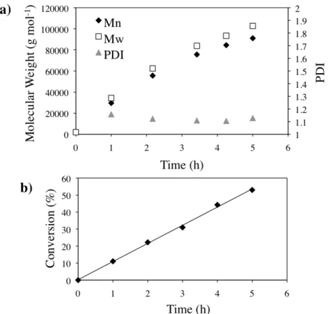
Using a sacrificial initiator, we have shown that in the presence of the clicked substrates there is a linear increase in molecular weight of polymer chains with time and addition of ascorbic acid, indicating that there are no termination, chain transfer, or initiation problems due to the presence of the substrates (Figure 2.2). For the remainder of the experiments, the polymer brushes were grown in the absence of a sacrificial initiator to prevent the adsorption of unattached growing chains to the surface.
Figure 1.2: Molecular weight (a) and conversion (b) of polymers in solution in the
presence of the clicked substrates.
1.1a), the appearance of peaks at 1100 cm---1, attributed to the C---O---C asymmetric stretching absorption, and 2850 cm---1, attributed to the C---O---C vibration absorption, indicate the increased presence of C---O bonds in comparison to the clicked substrate. In the XPS C1s spectrum, Figure 1.1d, the grafted substrates show the appearance of a peak at 287 eV, which indicates the presence of C---O single bonds.
A control sample was prepared by the submersion of a clicked sample in the ARGET reaction solution for 6h in the absence of ascorbic acid so that no polymerization occurred. The control sample looked identical to the clicked sample in both the ATR---FTIR and the XPS spectra, which indicates that the evidence for C---O single bond formation on the grafted samples in the ATR---FTIR and XPS is due to surface---initiated polymerization and not adsorption of OEGMA monomers.
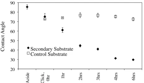
Figure 1.3: Static water contact angle for azide, clicked, grafted and control substrates in the secondary shapes. Control substrates were immersed in the ARGET reaction solution at 25 °C in the absence of polymerization for the indicated amount of time.
1.3.3 Surface Morphology and Wrinkling Behavior
Upon the grafting of poly(OEGMA) from the surface of a secondary substrate, we observed the presence of micron---sized, biaxial features by SEM. To return the grafted substrates to the primary shape, the materials were heated to 70 °C for 10 min, and cooled to ---4 °C for 10 min. Uniaxial wrinkles were observed on the returned substrates in addition to the features on the secondary substrate.
In an effort to understand the formation of the features and wrinkles, equilibration time (t1) and reaction time (t2) were investigated. Equilibration time is defined as the amount of time that the substrates were allowed to presoak in the ARGET ATRP solution prior to initiation of polymerization. Reaction time is the amount of time the ARGET ATRP reaction was allowed to progress before termination of the reaction by removal of the substrate from the ARGET solution.
minimum equilibration time, t1=0.5 h, showed features on the secondary substrate as well as wrinkle formation on the returned substrate. For t2 > 0.5 h, no feature or wrinkle formation was observed on the secondary or returned substrates.
Figure 1.4: SEMs of grafted substrates varying equilibration time, t1. The substrates
were equilibrated in the ARGET reaction solution at 25 °C for 0.5, 2, 6 and 21 h prior to grafting of poly(OEGMA) for 6 h.
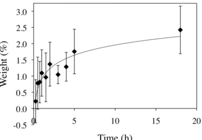
indicates that the substrates actually deswell in the ARGET reaction solution, so that with increased t1, the internal osmotic pressure decreases. For t1>0.5 h, the internal osmotic pressure has decreased below the critical value for wrinkling, so no wrinkles are observed.
Figure 1.5 Swelling of the clicked substrates in the ARGET reaction solution at 25
°C.
been reached, but the critical buckling strain (εc= ¼ (3Es/Ef)2/3) due to the deformation of the substrate to induce the formation of uniaxial wrinkles has been surpassed.25,26,27 In the t2=4 and 6 h samples, both the critical osmotic pressure and the critical buckling strain have been achieved, so both features and wrinkles are observed.
%
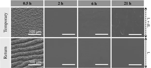
Figure 1.6 a) SEMs of ungrafted and grafted substrates varying reaction time, t2.
The substrates were equilibrated in the ARGET reaction solution at 25 °C for 0.5 h prior to grafting of poly(OEGMA) for 0, 2, 4 and 6 h. b) Feature size determination for the secondary substrates by image analysis. Average feature sizes were 4.9 ± 0.5 and 6.2 ± 1.4 μm for the 4 and 6 h substrates, respectively. c) Wavelength determination for the returned substrates by image analysis. Average wavelengths
were 27 ± 3, 30 ± 5 and 33 ± 5 μm for the 2, 4 and 6 h substrates, respectively.
Classical wrinkling mechanics dictate that the wavelength, λ, of a wrinkled material, defined as28
∃ E f
″ = 2#hf &
3E
′1/ 3 ) s (
positive correlation with reaction time, although it cannot be assumed that the relationship is linear. When comparing the wavelengths of the 2, 4 and 6 h samples, the larger wavelength of the 6 h sample is presumably due to a thicker brush layer. Alternatively, the 6 h sample also has a larger distribution than the 2 and 4 h substrates, so the larger wavelength could also be a function of the large size distribution observed for the feature sizes on the secondary substrate.
The wrinkles on the return substrate are due to a difference in strain between the shape memory substrate and the grafted brush layer. The high---density brushes grafted on the secondary shape are in an unstrained equilibrium conformation, while the substrate is in a strained secondary conformation. By triggering the return of the primary shape, the brush layer is unable to compress, leading to mechanical instabilities at the brush---substrate interface.
1.4 Conclusions
REFERENCES
(1) Genzer, J.; Groenewold, J. Soft Matter 2006, 2, 310---323.
(2) Li, B.; Cao, Y.---P.; Feng, X.---Q.; Gao, H. Soft Matter 2012, 8, 5728---5745. (3) Yang, Shu.; Khare, K.; Lin, P.---C. Adv. Func. Mater. 2010, 20, 2550---2564. (4) Lin, P.---C.; Yang, S. Soft Matter 2009, 5, 1011---1018.
(5) Lin, P.---C.; Vajpayee, S.; Jagota, A.; Hui, C.---Y.; Yang, S. Soft Matter 2008, 4, 1830--- 1835.
(6) Jeong, H. E.; Kwak, M. K.; Suh, K. Y. Langmuir 2010, 26, 2223---2226. (7) Xie, T.; Xiao, X.; Li, J.; Wang, R. Adv. Mater. 2010, 22, 4390---4394.
(8)Kim, J. B.; Kim, P.; Pégard, N. C.; Oh, S. J.; Kagan, C. R.; Fleischer, J. W.; Stone, H. A.; Loo, Y.---L. Nature Phototon. 2012, 6, 327---332.
(9) Efimenko, K.; Findlay, J.; Callow, M. E.; Callow, J. A.; Genzer, J. ACS Appl. Mater. Interfaces 2009, 1, 1031---1040.
(10) Efimenko, K.; Rackaitis, M.; Manias, E.; Vaziri, A.; Mahadevan, L.; Genzer, J.
Nature Mater. 2005, 4, 293---297.
(11)Khang, D. Y.; Jiang, H. Q.; Huang, Y.; Rogers, J. A. Science 2006, 311, 208---212. (12)Li, Z.; Zhang, S.; Zhang, P.; Yang, D.; Jin, G.; Ma, H. Polym. Adv. Technol. 2012, 23, 1240---1245.
(13)Bowden, N.; Brittain, S.; Evans, A. G.; Hutchinson, J. W.; Whitesides, G. M. Nature
1998, 393, 146---149.
(14)Yang, P.; Baker, R. M.; Henderson, J. H.; Mather, P. T. Soft Matter 2013, 9, 4705--- 4714.
(15) Chan, E. P.; Smith, E. J.; Hayward, R. C.; Crosby, A. J. Adv. Mater. 2008, 20, 711--- 716.
(16) Alzahrani, A. A.; Nair, D. P.; Smits, D. J.; Saed, M.; Yakacki, C. M.; Bowman, C. N.
Chem. Mater. 2014, 26, 5303---5309.
(17) Chung, J. Y.; Chastek, T. Q.; Fasolka, M. J.; Ro, H. W.; Stafford, C. M. ACS Nano
(18) Huang, H.; Chung, J. Y.; Nolte, A. J.; Stafford, C. M. Chem. Mater. 2007, 19, 6555--- 6560.
(19)Milner, S. T. Polymer Brushes. Science 1991, 251, 905---914.
(20) Barbey, R.; Lavanant, L.; Paripovic, D.; Schüwer, N.; Sugnaux, C.; Tugulu, S.; Klock, H.---A. Chem Rev. 2009, 109, 5437---5527.
(21)Fu, C.---C.; Grimes, A.; Long, M.; Ferri, C. G. L.; Rich, B. D.; Ghosh, S.; Ghosh, S.; Lee, L. P.; Gopinathan, A.; Khine, M. Adv. Mater. 2009, 21, 4472---4476.
(22) Brosnan, S. M.; Brown, A. H.; Ashby, V. S. J. Am. Chem. Soc. 2013, 135, 3067--- 3072.
(23)Simakova, A.; Averick, S. E.; Konkolewicz, D.; Matyjaszewski, K. Macromolecules
2012, 45, 6371---6379.
(24)Fan, X.; Lin, L.; Messersmith, P. Biomacromolecules 2006, 7, 2443---2448.
(25)Tanaka, T.; Sun, S. T.; Hirokawa, Y.; Katayama, S.; Kucera, J.; Hirose, Y.; Amira, T.
Nature 1987, 325, 796---798.
Chapter II
SOLUTION AND HETEROGENOUS POLYMERIZATION OF IODINE---CONTAINING METHACRYLATE COPOLYMERS FOR BIOMATERIAL APPLICATIONS
2.1Introduction
Some of the most common major orthopedic surgical procedures performed annually are hip replacements, knee replacements, balloon kyphoplasty and vertebroplasty, and with the aging population growing, the instances of these surgeries is expected to rise.1,2,3 Injectable acrylic bone cements, most often composed of poly(methyl methacrylate) (PMMA), are a vital component to these procedures.4 In joint replacement surgeries, bone cement is used to immobilize the prosthesis in the bone and to transfer body weight from the prosthesis to the bone. In vertebroplasty and balloon kyphoplasty, the cement is injected into a fractured vertebral body to stabilize and restore height. Commercial bone cements are comprised of a powder and a liquid portion that are mixed together immediately prior to injection. The powder contains PMMA beads, an inorganic radiopacifier and an initiator, benzoyl peroxide (BPO). The liquid contains methyl methacrylate (MMA) monomer and an accelerator, N, N---dimethyl---p---toluidine (DMPT).2,5
proportions of filler are needed for vertebral fracture repair because the surgery is guided by fluoroscopic X---ray.7 While inorganic additives make the cements easier to visualize by X---ray, there are some major mechanical and biological drawbacks.
Mechanically, the presence of these fillers can compromise the tensile strength8,9 and fracture toughness10 of the cements and promote crack propagation.11 Poor adhesion between the inorganic phase with the polymeric matrix, inefficient transfer of stress from the matrix to the fillers and aggregation of inorganic particles are to blame for the shortcomings of these composites.12,13,14 Fractures in the cement reduce implant lifetime, causing damage to surrounding tissue and necessitating the need for additional surgery to reattach the prosthesis or refill the vertebral cavity. Biologically, the presence of the inorganic additives can trigger macrophague---osteoclast differentiation that contributes to bone resorption and aseptic loosening.15 Additionally, the radiopacifier particles can become dislodged from the cement and enter the joint space, causing damage to the surfaces and increase the production of polyethylene wear debris.16,17,18
developed to date are aromatic based monomers with one to three iodines substituted on the aromatic ring.
Herein, we have developed a novel polymerizable monomer based on methyl methacrylate containing only aliphatic---bound iodine. The advantage of this monomer over previously synthesized iodine monomers is the high weight percent of iodine present in the monomer, which enables the incorporation of fewer functionalized monomers to obtain the desired radiopacity while also limiting the effect on mechanical properties. The iodine on this monomer is resistant to elimination and displacement due to the unique structure
2.2Experimental Methods
2.2.1Materials
Methyl methacrylate (99%) was de---inhibited with adsorption alumina. Benzoyl peroxide (98%) was recrystallized from diethyl ether and methanol or precipitated from CHCl3 with the addition of methanol. Methylene chloride was distilled from CaH2. All other materials were used as received from Sigma Aldrich, Fisher Scientific or VWR international. All reactions performed under inert atmosphere (N2) unless otherwise noted.
2.2.2Monomer and Polymer Characterization
and Waters gel permeation chromatography (GPC) system in THF relative to poly(methyl methacrylate) standards.
2.2.3Microsphere Characterization
Scanning electron microscopy (SEM). All SEMs were taken on a FEI Quanta 200 Field Emission Gun Environmental Scanning Electron Microscope in high vacuum mode. The samples were sputtered with ~2 nm of gold prior to imaging. Images were analyzed with ImageJ software to measure the diameters of the beads and determine the PDI.
Electron dispersion spectroscopy (EDS). Iodine content was obtained by EDS
using INCA PentaFet –x3 installed on an Hitachi S---4700 FESEM with an Si(Li) detector. Three areas of ~100 µm2 were mapped and averaged to determine iodine content.
2.2.4Bone Cement Characterization
X--ray computed tomography (CT). CT scans were performed on a GE eXplore
speCZT CT 120 with an x---ray tube voltage of 70 kV, an x---ray tube current of 50 mA, and an exposure time of 32 ms. Resolution of the reconstructions is 100 µm. To determine the Houndsfiend units, the images of the samples from three different layers was averaged in ImageJ.
Compression Modulus. Compression modulus was determined on an Instron
2.2.5Preparation of Monomer
Preparation of 3--iodo--2,2--bis(iodomethyl)propanol. 3---Bromo---2,2---
bis(bromomethyl)propanol (14.99 g, 46.2 mmol) was refluxed at 75 °C in saturated solution of sodium iodide (103.8 g, 692.5 mmol) in acetone (400 mL) for five days. The solution was filtered, and the solvent was removed by rotary evaporation. The yellow oil was redissolved in ethyl acetate and the organic layer was extracted with 5% sodium thiosulfate, water and brine and then dried over MgSO4. The organic layer was filtered and then dried by rotary evaporation to a yellow oil, washed with hexanes and filtered to yield a white crystalline solid. Yield: 16.52 g (35.5 mmol, 76.8%) 1H NMR (600 MHz, CDCl3, δ): 3.72 (s, 2H, HO---CH2), 3.36 (s, 6H, I---CH2).
Preparation of 3--iodo--2,2--bis(iodomethyl)propyl methacrylate (IMMA). To a solution of 3--iodo---2,2---bis(iodomethyl)propanol (16.52 g, 35.5 mmol) and triethylamine (7.5 mL, 53 mmol) in dry CH2Cl2 (200 mL), methacryloyl chloride (5.2 mL, 53 mmol) was added dropwise at 0°C. The solution was allowed to warm to room temperature and stir overnight. The solution was filtered and the organic layer washed with water (2x) and brine (1x) and then dried over MgSO4. The solution was filtered and dried by rotary evaporation. The yellow oil was purified by column chromatography in ethyl acetate and hexanes (87.5:12.5, Rf=0.595) followed by recrystallization from hot hexanes (~400 mL). White, needle---like crystals were collected and washed with cold hexanes. Yield: 11.93 g (22.4 mmol, 63.0 %). 1H NMR (600 MHz, CDCl3, δ): 6.11 (s, 1H, H2C=C), 5.63 (s, 1H, H2C=C), 4.25 (s, 2H, O---CH2), 3.39 (s, 6H, I---CH2), 1.97 (s, 3H, C=C---CH3).
Solution polymerization of poly(MMA--IMMA) copolymers. An example reaction is as follows: A solution of AIBN in toluene was prepared (9.2 mg AIBN, 18.0 mL toluene). To 7.50 mL of the AIBN solution, add MMA (5.87 g, 58.5 mmol) and IMMA (2.98 g, 5.58 mmol). The solution was purged with Ar for 20 min at r.t. The reaction was heated to 70 °C and allowed to proceed for 20 h. The reaction cooled to rt, dissolved in CH2Cl2 and precipitated into MeOH. 1H NMR (600 MHz, CDCl3, δ): 4.04 (m, H2C---O---), 3.60 (s, 3H, ---C---CH3), 3.39 (s, 6H, I---CH2), 2.10---1.65 (m, 2H, H2C---C), 1.29--- 0.51 (m, 3H, ---C---CH3).
Solvent evaporation of copolymers. . An example procedure is as follows: A polymer solution was prepared at a concentration of 0.075g/mL CHCl3. In a beaker, 30 mL of the polymer solution was added to a solution of sodium dodecyl sulfate (SDS) (2 w/v%, 150 mL) while stirring at a rate of 500 rpm, and was allowed to stir at this rate while covered for 1 hr. The cover was removed and the solution was allowed to stir overnight. The microspheres were collected via filtration, washed with water and dried in vacuo at 30 °C overnight.
2.2.7Suspension Polymerization of Copolymers
allowed to proceed for 4 hrs. The reaction was terminated by filtering the beads and rinsing with H2O (500 mL) and drying in vacuo at 30 °C overnight. 1H NMR (600 MHz, CDCl3, δ): 4.04 (m, H2C---O---), 3.60 (s, 3H, ---C---CH3), 3.39 (s, 6H, I---CH2), 2.10---1.65 (m, 2H, H2C---C), 1.29---0.51 (m, 3H, ---C---CH3).
2.2.8Preparation of Bone Cement
Bone cements were prepared from 60 wt% solid and 40 wt% liquid. The solid portion was comprised of 0.7375 g polymer beads (PMMA or copolymer) and 0.0125 g BPO. The liquid portion was comprised of 0.178 g DMPT and 8.714 g MMA. The solid portion (0.75 g) was mixed with 0.5 g of the liquid portion in a plastic dish in air. The cement was mixed for 45 seconds and then the resulting paste was put into a 1 mL syringe and compressed against the benchtop to create a cylinder. The cements were allowed to cure at room temperature. For the bone cement containing 10 wt% BaSO4, BaSO4 (0.0922 g), PMMA beads (0.6453 g) and BPO (0.0125 g) were mixed with 0.5 g of the liquid portion in the same manner as the other bone cements.
2.3Results and Discussion
2.3.1Iodinated Monomer Preparation
of monomer, but this affords a lower weight % iodine and can alter the mechanical properties of the bone cement significantly.
Scheme 2.1 Synthesis of IMMA monomer.
Most alkyl halides are good leaving groups and are therefore susceptible to elimination or substitution reactions and are therefore not suitable for in vivo
applications. The primary structure of the iodine of IMMA makes E1, SN1 and radical reactions unfavorable. The lack of β---hydrogens makes E2 reactions, unfavorable, but the iodine is still available for displacement by SN2 with moderate to strong nucleophiles (Scheme 2.2).
Scheme 2.2 The limited susceptibility of IMMA to E1, SN1, E2 and radical reactions
due to the primary structure of the iodine and the lack of β---hydrogens.
2.3.2Solution Polymerization of Copolymers
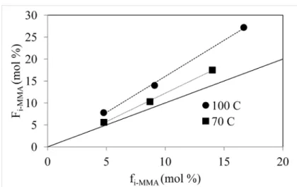
mol---1, as this was previously reported to be an ideal molecular weight for the powder portion of bone cement materials. Initially, polymers of three different feed ratios, fIMMA=4.7, 9.1 and 16.7 mol%, were synthesized at 100 °C, and the resulting copolymer ratios were FIMMA=7.8, 14.0 and 27.2 mol%. Suspecting that loss of MMA due to a low vapor pressure at the reaction temperature was the cause for the increased incorporation of the IMMA monomer into the polymer, the temperature of the reaction was lowered to 70 °C. At the lower reaction temperature fIMMA=4.8, 8.7 and 14.0 mol%, and the resulting incorporation into the copolymer were FIMMA=5.6, 10.3 and 17.5 mol%. Lowering the temperature reduced the loss of MMA, although the rate of incorporation of IMMA into the polymer was still higher than unity. This could be due to loss of MMA during reaction, or a reactivity difference between the two monomers (Figure 2.1).
Figure 2.1 Polymer composition, FIMMA, as a function of feed ratio, fIMMA, of the IMMA monomer synthesized by solution polymerization.
Utilizing a reaction temperature of 70 °C, a variety of copolymer compositions were synthesized varying the feed ratio of 6.0---27.0 mol% IMMA resulting in polymers with 17.1---47.6 wt% iodine. The maximum feed ratio of IMMA is ~30 mol% due to the limited solubility of the IMMA in MMA and toluene. Table 3.1 includes the molecular weights of the copolymers synthesized.
Table 2.1 Compositions and Molecular Weights of Copolymers Synthesized in
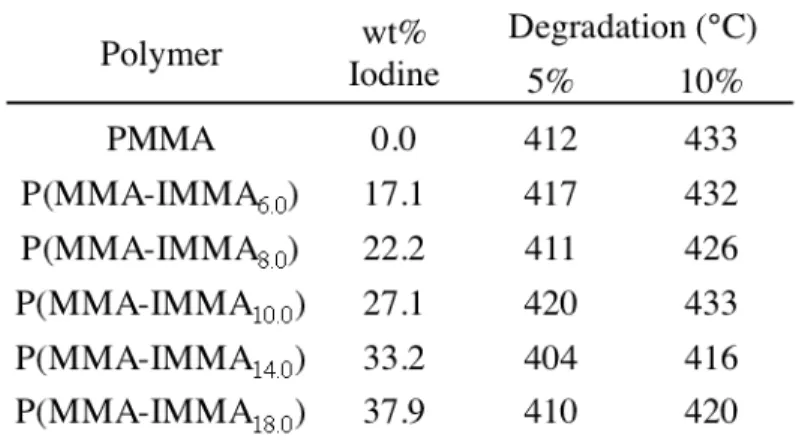
The thermal degradation of the resulting copolymers is similar to that of a PMMA material prepared by similar methods. This indicates that the onset of degradation is not triggered by the elimination of the iodine moieties, but is due to the thermal degradation of poly(methyl methacrylate). The thermal stabilities of the copolymers reflect the stability of the iodine monomer and the unfavorable loss of iodine by elimination or radical pathways (Table 2.2).
Table 2.2 Thermal Degradation Temperatures of Polymers Prepared by Solvent
Polymerization
molecular weight, so it can be concluded that the presence of the iodine monomer may be retarding the polymerization rate of MMA, but not causing chain transfer.
2.3.3 Fabrication of Microbeads by Solvent Evaporation
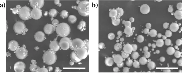
The synthesized copolymers were utilized to fabricate microbeads by a solvent evaporation method. In solvent evaporation, the polymer is dissolved in a good solvent, in this case chloroform, and a miniemulsion is formed upon addition to a continuous aqueous phase containing a stabilizer, in this case sodium dodecyl sulfate. The chloroform is then allowed to evaporate over several hours, resulting in a dispersion of microspheres. SEM images of PMMA and copolymer beads in Figure 2.2 show the spherical morphology attained utilizing this method.
Figure 2.2 SEM images of microspheres fabricated with 2 wt% SDS solution by
solvent evaporation. a) PMMA b) P(MMA---co---IMMA6.0) . Scale bar=100 µm.
large polydispersity is common with solvent evaporation methods, but is also common with other bone cement materials, so this would not present a challenge to the utilization of these materials in bone cement.
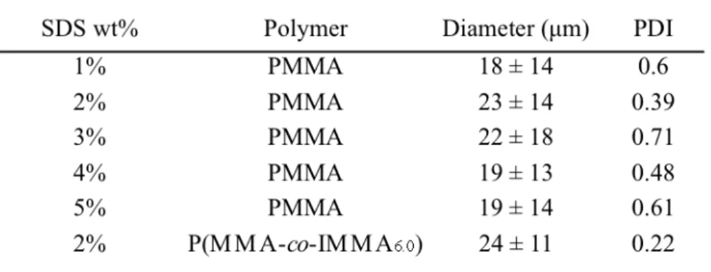
Table 2.3 Diameter of Microspheres Prepared by Solvent Evaporation
2.3.4 Suspension Polymerization of Copolymers
Scheme 2.4 Suspension polymerization of P(MMA---IMMA) copolymers.
Figure 2.3 SEM images of microspheres fabricated with 0.24% PVP, and0.25% BPO
by suspension polymerization. a) PMMA b) P(MMA---co---IMMA6.9). Scale bar=100 µm.
2.3.4.1 Molecular Weight and Bead Diameter
0.15---0.25 wt% (Figure 2.5). As expected with suspension polymerization, the bead diameter decreased with increasing PVP concentration, with a minimum bead size ~40 μm.
5
4
3
2
1
0
1
2
3
4
5
Target Molecular Weight (x 10
5Da)
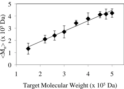
Figure 2.4 Experimental <Mn> of the suspension polymerization of P(MMA---IMMA)
copolymers. [BPO]=0.02 to 0.15 mol%.
500
400
300
200
100
0
0.14 0.16 0.18 0.2 0.22 0.24 0.26
[PVP] (wt %)
Figure 2.5 PVP concentration effect on bead diameter in the suspension
polymerization of P(MMA---IMMA) copolymers with a feed ratio of fIMMA=6.9 mol%.
The reaction was optimized to get beads with molecular weights of <Mn>~3.6x10⁵ g mol---1 and bead size of ~50 µm by using a BPO concentration of
0.25% and a PVP concentration of 0.24%. Copolymers with a variety of compositions with the desired molecular weight and bead size were successfully synthesized. The results of which are in Table 2.4 and Table 2.5. Also, it should be noted that the copolymer composition has a lower content of the iodinated monomer than the feed ratio (FIMMA<fIMMA), which will be discussed in a later section. As expected, the thermal stabilities of the synthesized copolymer beads in Table 2.6 were similar to non---iodinated PMMA and the copolymers synthesized by solution polymerization (Table 2.2).
Table 2.4 Molecular Weight of PMMA and P(MMA---IMMA) Copolymer Beads by
Suspension Polymerization
Table 2.5 Bead Size of PMMA and P(MMA---IMMA) Copolymer Beads by Suspension
Table 2.6 Thermal Degradation and Glass Transitions for PMMA and P(MMA--- IMMA) Copolymer Beads
2.3.4.2Reaction Kinetics
Figure 2.6 Kinetic study of suspension copolymerization of MMA and IMMA. (a) Overall conversion of copolymerization; (b) individual conversion of MMA and IMMA monomers; (c) instantaneous feed ratios of MMA (fMMA) and IMMA (fIMMA) and cumulative copolymer ratios of MMA (FMMA) and IMMA (FIMMA).
2.3.4.3Iodine Content
2.3.5Bone Cement Characterization
Bone cements were formulated with the radiolucent PMMA beads, PMMA beads containing 10 wt% BaSO4 and the radiopaque 20.5 wt% iodine copolymer beads. The powder to liquid ratio was kept constant at 60:40. It is common practice for surgeons to mix BaSO4 with existing commercial bone cements, so a sample containing this inorganic radiopacifying agent was included as a comparison to the synthesized materials.
2.3.5.1Radiopacity
Figure 2.7 Radiopacity of PMMA, P(MMA---co---IMMA6.9) copolymer and 10 wt% BaSO4 bone cements and an Al control. Dimensions: 2.5 x 0.5 cm cylinder. a) A central slice from the CT image. b) The average Hounsfield units (HU) calculated from the CT images.
2.3.5.2Compression Testing
Table 2.7 Compression Modulus of Bone Cements
2.4 Conclusions and Outlook
REFERENCES
(1)Kurtz, S.; Ong, K.; Mowat, F.; Halpern, M. J. Bone Joint Surg. Am. 2007, 89, 780--- 785.
(2)Dunne, N. Orthopaedic Bone Cements. CRC Press; 2008.
(3)Department of Research & Scientific Affairs, American Academy of Orthopaedic Surgeons. Annual Incidence of Common Musculoskeletal Procedures and Treatment. www.aaos.org/research/stats/CommonProceduresTreatments---March2014.pdf. March 2014.
(4) Charnley, J. J. Bone Jt. Surg. (Br) 1960, 42--B, 28---30.
(5)Kuhn, K---D. Bone Cements: Up---to---date Comparison of Physical and Chemical Properties of Commercial Materials. Berlin: Springer---Verlag; 2000.
(6)Lewis, G. J. Biomed. Mater. Res. Part B 2008, 84B, 301---319. (7)Lewis, G. J. Biomed. Mater. Res. Part B 2006, 76B, 456---468. (8) Kusy, R. P.; J. Biomed. Mater. Res. 1978, 12, 271---305.
(9) Hass, S. S.; Brauer, G. M.; Dickson, M. A. J. Bone Joint Surg. 1975, 57--A, 380---391. (10) Sih, G. C.; Berman, A. T. J. Biomed. Mater. Res. 1980, 14, 311---316.
(11)Ginebra, M. P.; Albuixech, L.; Fernandez---Barragan, E.; Aparicio, C.; Gil, F. J.; San Roman, J.; Vazquez, B.; Planell, J. A. Biomaterials 2002, 23, 1873---1882.
(12)Vila, M. M.; Ginebra, M. P.; Gil, F. J.; Planell, J. A. J. Biomed. Mater. Res. (Appl. Biomat.) 1999, 48, 128---134.
(13)Ginebra, M. P.; Aparicio, L.; Albuixech, L.; Fernandez---Barragan, E.; Gil, F. J.; Planell, J. A. J. Mater. Sci. Mater. Med. 1999, 10, 733---737.
(14)Topoleski, L. D. T.; Ducheyne, P.; Cuckler, J. M. J. Biomed. Mater. Res. 1990, 24, 135---159.
(15)Sabokbar, A.; Fujukawa, Y.; Murray, D. W.; Athanasou, N. A. J. Bone Joint Surg. (Br) 1997, 79--B, 129---134.
(16)Isaac, G. H.; Atkinson, J. R.; Dowson, D.; Kennedy, P. D.; Smith, M. R. Eng. Med.
(17)Caravia, L.; Dowson, D. Fisher, J.; Jobbins, B. Proc. Inst. Mech. Eng. 1990, 204, 65--- 70.
(18)Cooper, J. R.; Dowson, D.; Fisher, J.; Jobbins, B. J. Med. Eng. Technol. 1991, 15, 63---67.
(19)Kruft, M. A. B.; Benzina, A.; Blezer, R.; Koole, L. H. Biomaterials, 1996, 17, 1803--- 1812.
(20)Davy, K. W. M.; Anseau, M. R.; Odlyha, M.; Foster, G. M. Polym. Inter. 1997, 43, 143---154.
(21)Ginebra, M. P.; Aparicio, C.; Albuixech, L.; Fernandez---Barragan, E.; Gil, F. J.; Planell, J. A.; Morejon, L.; Vazquez, B.; San Roman, J. J. Mater. Sci. Mater. Med. 1999,
10, 733---737.
(22)van Hooy---Corstjens, C. S. J.; Govaert, L. E.; Spoelstra, A. B.; Bulstra, S. K.; Wetzels, G. M. R.; Koole, L. H. Biomaterials 2004, 25, 2657---2667.
(23)Boelen, E. J. H.; Lewis, G.; Xu, J.; Slots, T.; Koole, L. H.; van Hooy---Corstjens, C. S. J.
Chapter III
ENDGROUP FUNCTIONALIZATION OF POLY(ETHYLENE TEREPHTHALATE) DERITIVES WITH UREIDOPYRIMIDINONE
3.1Introduction
Telechelic endgroups have received a lot of attention for their ability to create reversible supramolecular polymers with properties not accessible by traditional polymerization routes.1,2 Supramolecular “polymers” can be synthesized by bringing together “monomers” with highly directional, self---assembling non--- covalent bonds. Initially, work focused on small molecule monomers, but more recently oligomers, have been end---functionalized to create macromers that can be chain extended via supramolecular chemistry. Endgroup moieties utilizing metal coordination,3 ionic interactions,4,5 host---guest complexes6 or hydrogen---bonding functionalities can be incorporated into directional complementary (A---B) or self--- complementary units (A---A) that will assemble into larger polymeric materials. Of
endgroups behaved as liquids.8 Recently, more sophisticated directional systems with multiple hydrogen bonds from urethane and urea functionalities have evolved, but one of the most common endgroups utilized to achieve the supramolecular effect is ureidopyrimidinone (UPy) due to the ease of synthesis and a high association constant, Kassoc>107 M---1.9,10,11 The effectiveness of this group can be attributed to existence of four complementary hydrogen---bonding sites and lateral aggregation of the endgroups.12,13,14 The direction dimerization behavior of this group is illustrated in Scheme 3.1. The introduction of terminal UPy groups can improve polymer properties concurrent with the increase in effective molecular weight via the self---complementary (A---A) endgroups and the formation of physical crosslinking sites via lateral aggregation.13,15,16 The resulting supramolecular thermoplastic elastomers are thermally reversible above the dissociation temperature of the UPy groups and exhibit shear thinning in the melt.
Scheme 3.1 The quadruple hydrogen bonding dimerization of two
ureidopyrimidinone (UPy) functionalities.
When added to the polymer, the UPy endgroup can have a significant effect on the properties of the functionalized materials, resulting in materials that can be processed into films with tensile properties. The strength at which the UPy groups associate, and therefore the virtual molecular weight and modulus of the material, can be tuned by eliminating hydrogen---bonding sites or modifying the length of the aliphatic spacer between the polymer and the isocytosine head.16 Fibril formation and film morphology is dependant on lateral aggregation and can be affected by the addition of aliphatic R groups on the isocytosine head.10 While the structure--- property relationships of low Tg materials have been well established, investigations probing the effect of the UPy endgroup on high Tg or high Tm materials have been limited.
In a study by Long and coworkers, polystyrene, a commodity plastic with a Tg~100 °C, was endcapped with a hydrogen bonding endgroup structurally similar to that of the UPy endgroup.19 The effect of the addition of this endgroup was an 8--- 20 °C increase in Tg and a 100---fold increase in the melt viscosity in comparison to the hydroxyl endcapped materials. In a prepolymer of 2400 g mol---1, the Tg increased from 72 to 92 °C. In systems where dimerization was determined to be the principal mode of supramolecular enhancement a significant increase in the Tg was not observed. Instead, the increase in the Tg was attributed to the presence of aggregates in the melt. This work did not go on to study the mechanical repercussions of the hydrogen bonding endgroup, but it did show that hydrogen--- bonding endgroups have a significant impact on the polymer properties of high Tg plastics.
One of the major drawbacks of hydrogen---bonded supramolecular materials is the high degree of creep that can occur while under load, but it has been suggested that strong interchain interactions and crystalline domains have the potential to prevent creep, and can possibly lead to thermoplastic elastomers with enhanced properties.1 One genre of polymers that fulfills these requirements is aromatic polyesters. The polyester functionalities in the backbone and π---π stacking amplify interchain interactions, leading to high Tg and high Tm materials. Herein, we investigate the effect of the UPy endgroup on poly(ethylene terephthalate) derivatives modified with cyclohexanedimethanol (CHDM), PETG, of different molecular weights. Hydroxyl---endcapped PETG polymers with molecular weights of 2000, 3800 and 6800 g mol---1 were endcapped with the UPy moiety and studied in solution and in films.
3.2Experimental Methods
3.2.1Materials
3.2.2Polymer Characterization
PETG and UPy functionalized polymers were characterized in CDCl3 using a Bruker 600 AVANCE 1H NMR, TA Instruments Q200 differential scanning calorimeter (DSC) (heating rate=10 °C/min, cooling rate=5 C°/min), Perkin Elmer Pyris 1 TGA (thermogravimetric analyzer) (TGA) (heating rate=5 °C/min), Waters gel permeation chromatography (GPC) system in CHCl3 relative to polystyrene standards, and attenuated total reflectance Fourier transform infrared spectroscopy (ATR---FTIR) using a Bruker ALPHA FT---IR spectrometer.
3.2.3Film and Solution Characterization
Dynamic Mechanical Analysis to determine the storage modulus at 30 and 100 °C and Tg was performed on a TA Istruments G2 RSA. Strain at yield, strain at break, stress at yield, stress at break and Young’s Modulus was determined on an Instron 5566. Viscosity measurements were performed on a TA Instruments G2 ARES.
3.2.4PETG Modification
overnight at 90 °C. The product is then cooled to ---78 °C and ground into a powder with a modified coffee grinder and dried in vacuo overnight at 100 °C. Yield: 13.65 g (63 %). 1H NMR δ (ppm): 13.10 (s, 1H), 11.81 (s, 1H), 10.11 (s, 1H), 8.09 (s, 4H) 5.81 (s, 1H), 5.07 (s, 1H), 3.23 (bs, 2H), 3.16 (bs, 2H), 2.20 (s, 3H), 1.58 (bs, 2H), 1.35 (bs, 2H).
Modification of 3.8K PETG. The procedure is the same as above, except 11.2 g PETG3.8K was combined with 2.6 g MIS in 250 mL anhydrous CHCl3. Yield 6.56 g (59%).
Modification of 2K PETG. The procedure is the same as above, except 10.0 g
PETG2K was combined with 4.4 g MIS in 500 mL anhydrous CHCl3. Yield: 7.16 g (55%).
3.2.5Solution Film Casting
3.2.5.1Filtering
3.2.5.2Centrifugation
1 g of polymer was dissolved in 40 mL CHCl3 and centrifuged at 4000 rpm for 1 h. The solution was decanted or pipetted off and then the solvent was removed by rotary evaporation. The polymer was then redissoved in 1,3,5---trichlorobenzene (~25 wt% for PETG, ~13 wt% for functionalized polymers). The solution was warmed to 120 °C and cast onto hot (120 °C) clean glass with a doctor blade. The film was heated to 120 °C for 16 h at ambient pressure. The film was then put under reduced pressure and the temperature was raised to 190 °C for 6 h. To remove the film from the glass, the film was put into a 50---80 °C water bath for several hours until the film came away from the glass easily. The film was dried with a lint---free paper towel.
3.2.6Tensile Testing
Dynamic Mechanical Analyzer (DMA). Strips of 5 mm width were subjected to
a temperature sweep from 25 °C to 120 °C at a heating rate of 3 °C/min with a prestrain of 0.1N axial force, frequency of 1 Hz and a strain of 0.1% .
Instron. Samples with widths of 3 mm were put under a tensile load at a rate of 10 mm/min at room temperature.
3.2.7Viscosity Testing
3.3Results and Discussion
3.3.1Endgroup Modification
The endgroup modification of the PETG polymers was achieved by reacting the isocyanate functionality of the UPy endgroup with the hydroxyl endgroups of PETG polymer in solution (Scheme 3.2). This synthetic method is well established for polymers such as PEB,10 but Long and coworkers utilized a bulk reactive extrusion method in their work with aromatic polyesters, PIT and PBT.15 To remove the excess endgroup, silica gel was added and the unreacted isocyanate reacted with the hydroxyl functionalities on the surface of the silica gel. Removal of the silica gel was initially performed by vacuum filtration over paper, but it was found that this method insufficiently removed the silica gel, so filtering over a sand column was adopted.
Scheme 3.2 Reaction of hydroxyl---endcapped PETG polymers in solution with UPy
endgroup functionality.
3.3.2Chemical Characterization
presence of the UPy endgroups. Integrations of the UPy endgroup peaks and the aromatic peak of the PETG indicate full functionalization of the PETG polymers. The appearance of the peak at 3.23 ppm also indicates reaction of the isocyanate group with a hydroxyl functionality to form an adjacent urethane moiety.
Figure 3.1 1H NMR in CDCl3 of the PETG polymer (top) and the UPy---functionalized
PETG polymer (bottom). Peaks indicating the presence of the UPy endgroup are labeled.
appearance of the amide I and II bands at 1660 and 1580 cm---1 as well as the appearance of a peak at 1510 cm---1 attributable to a secondary amine indicate the presence of the UPy endgroup in the product.
Figure 3.2 The ATR---FTIR of the PETG2K, PETG2K---UPy and UPy endgroup. a) Full
spectrum, and b) inset from 2000---1200 cm---1.
3.3.3Molecular Weight
in the purification. This could be due to the affinity of the UPy endgroup to silica gel, which has been observed previously, and some of the lower molecular weight fractions may remain with the silica gel after filtering. This could be an additional explanation for the observed increase in the molecular weight.
Figure 3.3 GPC traces of the PETG polymers and the polymers post---
functionalization.
Table 3.1 Molecular Weights of PETG and PETG---UPy Polymers
a) Determined by GPC in THF using polystyrene standards.
3.3.4Thermal Degradation
Figure 3.4 Thermal gravimetric analysis (TGA) traces in air of the functionalized and unfunctionalized PETG polymers. PETG materials were degraded from the bulk material, and the functionalized materials degraded after processing into films at 190 °C.
Table 3.2 Thermal Degradation of PETG and PETG---UPy Polymers
a) Bulk material b) after processing into films at 190 °C
3.3.5Thermal Transitions
confirm that the increase in the Tg is due to the endgroup functionalities and is not a artifact of processing, the PETG films should processed in the same manner.
Table 3.3 Glass Transition Temperatures of PETG and PETG---UPy Polymers
a) Bulk material b) after processing into films at 190 °C
Figure 3.5 DSC traces of the first and second heats of PETG6.8K---UPy (a) and PETG3.8K---UPy (b) after heating to 120 °C.
Figure 3.6 DSC traces of the first and second heats of PETG2K---UPy (a), PETG3.8K---UPy (b) and PETG6.8K---UPy (c) after heating the films to 190 °C.
3.3.6Viscosity
Figure 3.7 Viscosity of 2.5---12.5 wt% solutions in 1,3,5---trichlorobenzene of PETG6.8K (a) and PETG6.8K---UPy (b). Shear rates from 5x10---5---50 1/s at a temperature of 80 °C.
3.3.7Film Formation and Tensile Testing