Development of a Fuzzy Controller with
UPFC’s For
Damping
of Oscillation in Multi-machine Integrated Power System
Vibha N. Parmar Electrical Engineering Department,
Goverment Engineering Collage. Bhuj-370001, India [email protected]
Ashok L. Vaghamshi Asst. Professor
Electrical Engineering Department,
Government Engineering Collage, Bhuj-370001, India. [email protected]
Abstract—In This paper damping of oscillations in FACTS based integrated multi-machine power system. When 3 phase to ground symmetrical fault is made to occur near each generator. (one fault at a time). The multi-machine system consists of 3 generators, 3 transformers, 9 buses, 4 loads & 2UPFCs. Simulations are performed with & without the controller. UPFC based POD controllers can be used to suppress the oscillations upon the occurrence of a fault at the generator side . This paper depicts about this hybrid combination of a fuzzy with a UPFC & POD control strategy to damp the electro-mechanical oscillations. Digital simulations of a multi-machine power system subjected to a wide variety of disturbances are validating the efficiency of the power system.
Key Words — FACTS (UPFC), Power oscillation damping (POD), Fuzzy logic, Coordination, Controller, Oscillations, Damping, Stability, Simulink, State space model.
I. I
NTRODUCTIONAccording to IEEE, FACTS - which is the abbreviation of Flexible AC Transmission Systems, is defined as
“alternating current transmission systems incorporating power electronics based and other static controllers to enhance controllability and power transfer capability”. The FACTS initiative was originally launched in 1980’s to
solve the emerging problems faced due to restrictions on transmission line construction, and to facilitate growing power export / import and wheeling transactions among utilities. The two basic objectives behind the development of FACTS technology; is to increase power transfer capability of transmission systems, and to keep power flow over designated routes, significantly increase the utilization of existing (and new) transmission assets, and play a major role in facilitating contractual power flow in electricity markets with minimal requirements for new transmission lines.
FACTS plays a very important role. Usage of FACTS in the power systems not only enhances the dynamic performance, but also increases the stability of the power systems, enhances the controllability & increases its power transfer capability. Some of the devices used in the control of FACTS are the SVC, TCSC, STATCOM, UPFC, and the IPFC. The FACTS controllers utilize power electronics based technology and can provide dynamic control on line power flows, bus voltages, line impedance & phase angles. FACTS technology opens up new opportunities for controlling power and enhancing the usable capacity of present as well as new and upgraded lines. The FACTS technology is not a single high power controller, but rather
a collection of Controllers. In general facts controller are of four types
1. Series Controllers. 2. Shunt controllers.
3. Combined series-series controllers. 4. Combined series-shunt Controllers.
Here we use combined series shunt controller. In this UPFC (Unified power flow control) is the most powerful FACTS device. Gyugyi proposed the Unified Power Flow Controller which is the new type generation of FACTS devices in the year 1991. UPFC being one the member of the FACTS device thus emerged as one of the effective controllers for controlling and optimization of the power flow in the electrical power transmission systems Here line impedance, terminal voltages, and voltage angle can be controlled by UPFC. UPFC is a combination of STATCOM and SSSC. These two are voltage source converters. These are connected to each other by a common DC link, which is a typical a storage capacitor. The all parameters of the power transmission line (impedance, voltage and phase angle) can be control simultaneously by UPFC. In addition, it can perform the control function of the transmission line real / reactive power flow, UPFC bus voltage and the shunt-reactive-power flow control. The well designed FACTS controllers increases Transients and dynamic stability and also damps the electro mechanical oscillations. [1].
In an interconnected power system, the synchronous generators should rotate at the same speed and power flows over tie-lines should remain constant under normal operating conditions. However, low frequency (0.2 Hz. to 2 Hz.) electromechanical oscillations may occur when a disturbance is applied to the power system. These oscillations can be observed in most power system variables like bus voltage, line current, generator rate and power. Power system oscillations were first observed as soon as synchronous generators were interconnected to provide more generation capacity and more reliability to a power system. Hence, this concept, i.e., the control of power system oscillations with fuzzy scheme & POD -UPFC is used in this paper. This trio concept not only improves the dynamics & the characteristics of the power system, but also increases the stability. This can be observed in the simulation results presented in section 5 in this paper.
section III, the control strategy, the design of the controller for all the 3 models is presented. Section IV presents the development of the 3 Simulink models for the damping of the power system oscillations when fault takes place near each generator, individually at a time. Simulation results are presented in section V. Conclusions are finally presented at the end in section VI. This is followed by the acronyms & the references.
II. M
ODELLING OFT
HE3-M
ACHINE, 9-B
USI
NTEGRATEDP
OWERS
YSTEMThe integrated multi-machine power system model consisting of 3 generators used for the simulation purposes is shown in the form of a single line diagram with the controllers in the Fig.1. The generators 1, 2 and 3 are
connected to buses 1, 5 and 8. Two UPFC’s are used for
controlling & damping the power system oscillations in the integrated plant . One is connected between bus 2 & 3 and the other is connected between buses 6 and 7. Three transformers T1 to T3 are also used in the integrated power system near the generator buses for the power transmission purposes, i.e., for stepping up & stepping down purposes. Transmission lines are connected between the buses 3-9-4-6. Since, we know that the power system is a dynamic one, definitely, it is a non-linear system. For modelling & simulation purposes in the Matlab-Simulink environment, a numerical model is needed. By linearizing about an operating point, the total linearized power system model (the plant model) is represented finally in the state space form as
where,Δx is the state vector of length equal to thenumber of states n, Δy is the output vector of length m,Δu is the
input vector of length r, A is the system state matrix of size (n × n), B is the control input vector of size (n × r), C is the control input vector of size (m × n), D is the feed-forward matrix of size (m × r)
Fig.1. A 3-machine, 9-bus interconnected power system model with 4-loads & 2 POD-UPFC & the fuzzy controller
III. D
EVELOPMENT OFT
HEC
ONTROLS
TRATEGYA controller is a device which controls each & every operation in the system making decisions. From the control system point of view, it is bringing stability to the system when there is a disturbance or a noise or a fault, thus safeguarding the equipment from further damages. It may be hardware based controller or a software based controller or a combination of both. In this section, the development of the control strategy for damping the oscillations in FACTS based power systems is presented.
The unified power flow controller (UPFC) is one of the most promising device & most versatile controller device used in the FACTS family. It is an electrical device for providing fast-acting reactive power compensation on high voltage transmission networks & is generally used as a controller in loop with the plant. It has the capability to control voltage magnitude, line impedance and phase angle, and can also independently provide (positive or negative) reactive power injections, thus providing the voltage support, control of power flow, & can be used to control active and reactive power flows in a transmission line.[1]-[4].
The concept of UPFC makes it possible to handle practically all power flow control and transmission line compensation problems, using solid state controllers, which provide functional flexibility, generally not attainable by conventional thyristor controlled systems. It has a capability of improving both steady-state and dynamic performances of a power system as they allow more accurate control of the power flow, better and faster control of voltage and system stability. [8]. It can be connected in series with a transmission line inside a system or in a tie-line connecting sub-systems in a large interconnected power system. Moreover, UPFC further improves the dynamic performance of the power system in coordination with damping controllers [7]. As a result, one of their applications is the damping of power system oscillations using Power Oscillation Damping (POD), which recently has been attracting the interest of many researchers, including ours.
series with the transmission line through series transformer.
The main task of the UPFC is to control the flow of power in steady-state conditions. In addition, high speed of operation of thyristor devices makes it possible to control real and reactive power flow. The UPFC can be employed to enhance power system damping by modulating the converter voltages. The UPFCs are used at certain locations in a integrated power system in between some buses. In the Fig. 3 shown, the i and j represents the buses in the integrated power system model. In our work considered, we have taken the total number of buses to be 9 & Two UPFCs connected between bus 2, 3 and 6, 7.
Fig. 2. A block diagram of the UPFC scheme used in FACTS (single line diagram)
Commonly the POD controllers involve a transfer function consisting of an amplification link, a washout link and two lead-lag links shown in Fig.3. In this paper the active power of the transmission line is used as input signal. The UPFC POD controller works effectively in single machine system. In order to improve the dynamic performance of a multi-machine system, the behaviour of the controllers must be coordinated. Otherwise the power system will be deteriorated.
Fig. 3. UPFC POD controller
Most of the FACTS POD controllers belong to the PI (proportional integral) type and work effectively in single machine system especially, after the parameter optimization, the damping of power system oscillations is perfectly achieved. However the performance of the above mentioned POD controllers deteriorates in multi-machine system.
Fig. 4. A diagrammatic view of a typical fuzzy logic controller used along with POD-UPFC for controlling the
oscillations in a power system.
In this paper the fuzzy logic controller is used to coordinate between the various parameters of the multi-machine based FACTS power system along with the POD-UPFC as shown in the block diagram in the Fig. 4. These fuzzy controllers have got a lot of advantages compared to the classical (P, PI, PID) & the conventional controllers (POD UPFC), such as the simplicity of control, low cost, high reliability, compactness of the hardware (since fuzzy logic controller just makes use of fuzzy rules) and the possibility to design without knowing the exact mathematical model of the process. Fuzzy logic is one of the successful applications of fuzzy set in which the variables are linguistic rather than the numeric variables & emerged as a consequence of the 1965 proposal of fuzzy set theory by Lotfi Zadeh. Linguistic variables, defined as variables whose values are sentences in a natural language (such as large or small), may be represented by the fuzzy
sets. Fuzzy set is an extension of a ‘crisp’ set where an
element can only belong to a set (full membership) or not belong at all (no membership). Fuzzy sets allow partial membership, which means that an element may partially belong to more than one set. A fuzzy set A of a universe of discourse X is represented by a collection of ordered pairs of generic element x→X and its membership functionμ:
X→ [ 0 1], which associates a numberμA(x) : X→ [ 0 1],
to each element x of X. A fuzzy logic controller is based on a set of control rules called as the fuzzy rules among the linguistic variables. These rules are expressed in the form of conditional statements. Our basic structure of the fuzzy logic coordination controller to damp out the oscillations in the power system consists of 3 important parts, viz., fuzzification, knowledge base - decision making logic (inference system) and the defuzzification, which are explained in brief as follows [9].
The necessary inputs to the decision-making unit blocks are the rule-based units and the data based block units. The fuzzification unit converts the crisp data into linguistic variables. The decision making unit decides in the linguistic variables with the help of logical linguistic rules supplied by the rule base unit and the relevant data supplied by the data base [8, 4]. The output of the decision-making unit is given as input to the de-fuzzification unit and the linguistic variables of the signal are converted back into the numeric form of data in the crisp form [4]. The decision-making unit uses the
conditional rules of ‘IF-THEN-ELSE’,
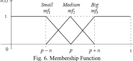
The inputs Pupfc1 and Pupfc2 are the active power flow through the UPFC1 and UPFC2.The output signals are command signals adjusted to the UPFC controllers 1 and 2. In this way, the conventional POD controllers are tuned by using fuzzy-coordination controllers. Fuzzification is a process whereby the input variables are mapped onto fuzzy variables (linguistic variables). Each fuzzified variable has a certain membership function. The inputs are fuzzified using three fuzzy sets: B (big), M (medium) and S (small)
Fig. 6. Membership Function
The developed fuzzy rules included in the fuzzy coordinated controller is given below in the form of an algorithm as follows :
1. If (Pupfc1 is mf1) and (Pupfc2 is mf1) then (output1 is mf3) (1)
2. If (Pupfc1 is mf1) and (Pupfc2 is mf2) then (output1 is mf2) (1)
3. If (Pupfc1 is mf1) and (Pupfc2 is mf3) then (output1 is mf1) (1)
4. If (Pupfc1 is mf2) and (Pupfc2 is mf1) then (output1 is mf3) (1)
5. If (Pupfc1 is mf2) and (Pupfc2 is mf2) then (output1 is mf2) (1)
6. If (Pupfc1 is mf2) and (Pupfc2 is mf3) then (output1 is mf1) (1)
7. If (Pupfc1 is mf3) and (Pupfc2 is mf1) then (output1 is mf3) (1)
8. If (Pupfc1 is mf3) and (Pupfc2 is mf2) then (output1 is mf2) (1)
9. If (Pupfc1 is mf3) and (Pupfc2 is mf3) then (output1 is mf1) (1)
Control decisions are made based on the fuzzified variables. Inference involves rules for determining output decisions. Due to the input variables having three fuzzified variables, the fuzzy-coordination controller has nine rules for each UPFC controller. The rules can be obtained from the system operation and the knowledge of the operator. To determine the degree of memberships for output variables, the Min- Max inference is applied. Both of the two UPFC controllers use the same inference system. Only the input of them are exchanged. There are so many methods to perform the defuzzification, viz., centre of gravity method, centre of singleton method, maximum methods, the marginal properties of the centroid methods & so on. In our work, we use the centre of gravity method.
Table-I: The 9-fuzzy rules used for determining the output decisions (Inference table) rule base used for the control
purposes
IV. D
EVELOPMENT OFT
HES
IMULINKM
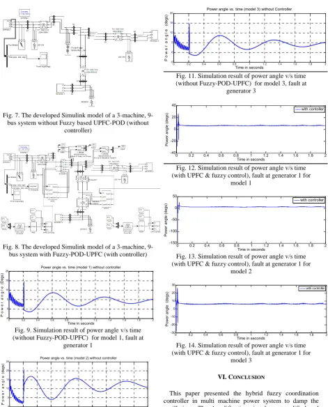
ODELIn this section, we present the development of the Simulink model for the multi-machine FACTS based power system with and without the controller. The Figs.7-8 show the simulation models of the 3- generator, 9-bus system installed with two Fuzzy-POD-UPFC controllers, i.e., first one between 2nd and the 3rd bus and second one is at 6th and 7th bus when the fault takes place near generators 1, 2 & 3.terminal The entire system modeled in Simulink is a closed loop feedback control system consisting of the plants, controllers, comparators, feedback systems, the mux, de-mux, integrators, state-space models, sub-systems, transformers, the output sinks (scopes) & the input sources. The Simulink model is developed from the basic functions available in the Simulink library & from the various tool-boxes available.
This system in Fig.8 is an open loop control system because of the absence of the controller. The 3 phase to ground symmetrical fault is also made to occur near the first generator terminal for 200 ms from the first cycle to the tenth cycle like in the model with the controller. This is done in order to compare the effectiveness of the incorporated controller in the model when the fault takes place with the model without the controller when the fault takes place. In this paper the model shown in Fig.8 in this fault is taken near generator 1, model 1 and in our work one fault at a time so fault is taken near generator 2 and 3 have model 2 and model 3 respectively.
V. S
IMULATIONR
ESULTSFig. 7. The developed Simulink model of a 3-machine, 9-bus system without Fuzzy based UPFC-POD (without
controller)
Fig. 8. The developed Simulink model of a 3-machine, 9-bus system with Fuzzy-POD-UPFC (with controller)
0 0.2 0.4 0.6 0.8 1 1.2 1.4 1.6 1.8 2 -5
0 5 10 15 20
Time in seconds
P
o
w
e
r
a
n
g
l
e
(D
eg
s)
Power angle vs. time (model 1) without controller
Fig. 9. Simulation result of power angle v/s time (without Fuzzy-POD-UPFC) for model 1, fault at
generator 1
0 0.2 0.4 0.6 0.8 1 1.2 1.4 1.6 1.8 2 0
5 10 15 20 25
Time in seconds
P
o
w
e
r
a
n
g
l
e
(d
eg
s)
Power angle vs. time (model 2) without controller
Fig. 10. Simulation result of power angle v/s time (without Fuzzy-POD-UPFC) for model 2, fault at
generator 2
0 0.2 0.4 0.6 0.8 1 1.2 1.4 1.6 1.8 2 -5
0 5 10 15 20
Time in seconds
P
o
w
e
r
a
n
g
l
e
(
de
gs
)
Power angle vs. time (model 3) without Controller
Fig. 11. Simulation result of power angle v/s time (without Fuzzy-POD-UPFC) for model 3, fault at
generator 3
0 0.2 0.4 0.6 0.8 1 1.2 1.4 1.6 1.8 2 -40
-20 0 20 40
Time in seconds
Po
w
er
a
ng
le
(d
eg
s)
with contoller
Fig. 12. Simulation result of power angle v/s time (with UPFC & fuzzy control), fault at generator 1 for
model 1
0 0.2 0.4 0.6 0.8 1 1.2 1.4 1.6 1.8 2 -150
-100 -50 0 50
Time in seconds
Po
w
er
a
ng
le
(d
eg
s)
with controller
Fig. 13. Simulation result of power angle v/s time (with UPFC & fuzzy control), fault at generator 1 for
model 2
0 0.2 0.4 0.6 0.8 1 1.2 1.4 1.6 1.8 2 -30
-20 -10 0 10 20 30
Time in seconds
Po
w
er
a
ng
le
(
de
gs
) with controller
Fig. 14. Simulation result of power angle v/s time (with UPFC & fuzzy control), fault at generator 1 for
model 3
VI. CONCLUSION
generator fault in multi machine system with controller and without controllers. The developed control strategy is not only simple, reliable, and may be easy to implement in real time applications. There are lot of ringing oscillations (overshoots & undershoots) & the output takes a lot of time to stabilize, which can be observed from the simulation results. But, from the incorporation of the Fuzzy-POD-UPFC coordination system in loop with the plant in all the 3 models, gave better results there by reducing the disturbances in the power angle and also the post fault settling time also got reduced a lot. The system stabilizes quickly, thus damping the local mode oscillations and reducing the settling time immediately after the occurrence of the fault. The developed control strategy is not only simple, reliable, and may be easy to implement in real time applications. The performance of the developed method in this work thus demonstrates the damping of the power system oscillations using the effectiveness of Fuzzy-POD-UPFC coordination concepts over the damping of power system oscillations without the Fuzzy-POD-UPFC coordination scheme.
R
EFERENCES[1] N.G.Hingorani, L.Gyugyi,"Understanding FACTS Concept and Technology of Flexible ac Transmission System", IEEE Press, New York,1999.
[2] DAKKA OBULESU, DR. S. F. KODAD, DR. B V. SANKAR RAM-“Damping of oscillation in multi-machine integrated
power system using hybride fuzzy strategies”, international
journal of research and reviews in applied sciences. Volume 1, Issue 2(November 2009).
[3] DAKKA OBULESU, DR. S. F. KODAD, DR. B V. SANKAR RAM-“Novel development of a fuzzy control scheme with upfc’s
for damping of oscillation in mult-imachine power system”,
international journal of reviews in computing. E-ISSN: 2076-3336.
[4] L.Gyugi, “Unified Power flow concept for flexible AC transmission systems”,IEE 1 Proc., Vol. 139, No. 4, pp. 323–
332, 1992
[5] M. Noroozian, L. Angquist, M. Ghandari, and G. Anderson, “Use of UPFC for optimal power flow control”,IEEE Trans. on Power Systems, Vol. 12, No. 4, pp. 1629–1634, 1997.
[6] Nabavi-Niaki and M.R. Iravani, “Steady-state and dynamic models of unified power flow controller (UPFC) for power
system studies”,IEEE’96 Winter Meeting, Paper 96, 1996. [7] S.N. Dhurvey and V.K. Chandrakar: “Performance Comparsion
of UPFC in Coordination with Optimized POD and PSS On
Damping of Power System Oscillations”,WSEAS Transactions on Power Systems, Issue 5, Vol. 3, pp. 287-299, May 2008.
[8] K.R. Padiyar, K. Uma Rao, “Modeling and Control of UPFC for
Transient Stability”,Elsevier Journal of Electrical Power Energy Systems, N0. 21, pp. 1- 11, 1999.
[9] H.F. Wang, “Application of Modeling UPFC Into Multi-Machine
Power Systems”,IEE Proc.Gen. Trans. and Distrib. Vol. 146,
No. 3, pp. 306–312, 1999.
[10] Lijun Cai, Istvan Erlich, “Fuzzy coordination of FACTS controllers for damping power system oscillations”, Proc. Of the
Int. Symp. On Modern Electronic Power Systems, Wroclaw, pp. 251-256, Sept. 11-13, 2002.
[11] S. Hongbo, D.C Yu. Luo Chunlei, “A novel method of power
flow analysis with unified power flow controller (UPFC)”, Power Engineering Society Winter Meeting, 2000, pp. 2800–
2805, Vol. 4, 23-27 Jan. 2000.
[12] P. K. Dash, S. Mishra, and G. Panda, “Damping Multi-modal Power System Oscillation Using a Hybrid Fuzzy Controller for Series Connected FACTS Devices”, IEEE Trans. on Power Systems, Vol. 15, No. 4, pp. 1360–1366, Nov. 2000.
[13] P.K. Dasha, S. Mishra, “Damping of multimodal power system
oscillations by FACTS devices using non-linear Takagi-Sugeno
fuzzy controller”,Proc. Electrical Power and Energy Systems,
Vol. 25, pp. 481–490, 2003.
A
UTHOR’
SP
ROFILEVibha Parmar
is a master degree student of Government Engineering College, Bhuj, Gujarat Technological University, Ahmedabad, Gujarat. She received B. E. degree in Electrical Engineering from Gujarat University in the year 2009. She also completed her Diploma Engineering in Electrical from TEB in the year 2005. Her areas of interests are Power System, Fuzzy Logic, Artificial Intelligence, Power Electronics, MATLAB and FACTS.
Ashok Vaghamshi
graduated from L. D. College of Engineering, Ahmedabad, Gujarat in the year 2007. He completed his Master degree from the same college in Electrical Engineering (Power System) in the year 2009. He completed his master degree dissertation from Power