INTRODUCTION
In coal mines and incineration plants it is necessary to have an overview and records of coal quality [1, 2, 3]. The aim is to maintain and check high quality of coal at stable favour-able prices even with respect to the environment [4]. Samples are usually taken directly from the transport route [5] even several times per shift. Theses samples are further checked in accredited laboratories. The sampling equipment and sys-tems play an important role here. Innovation in the field of sampling equipment involves auto-mation of the sampling operation. To implement this automation, it is necessary to know all the possible operating modes of the sampling equip-ment. In the field of studying processes and inves-tigating operating modes of transport equipment, which work with particulate materials, the use of the Discrete Element Method (DEM) [6, 7, 8, 9] presents itself. The input parameters for the DEM
are mechanical-physical properties, which best describe a specific particulate material. Typically, these include grain size, material density, friction between particles and contact geometry [10, 11].
The DEM can be used for the analysis and study of processes occurring inside the equip-ment, where one cannot see with, for example, an optical device to record video and collect data [12]. This can be used to find critical passive ar-eas of material flow, or other undesirable and in-efficient modes of the equipment [13].
However, to vindicate the quality or correct-ness of the simulation it is still necessary to per-form measurements. Important aspects include transport outputs of equipment, weight emptying of equipment in time, possible dynamic or me-chanical loading and material properties [14, 15, 16, 17, 18, 19, 20, 21, 22]. The use of the DEM alone does not necessarily have the correct pred-icative value without previous knowledge from measurements on investigated equipment.
Cali-SIMULATION OF MATERIAL FLOW THROUGH A SAMPLE DIVIDER
Jiri Rozbroj1, Jan Necas1*, David Zurovec1, Jakub Hlosta1, Daniel Gelnar1, Jiri Zegzulka1
1 VSB-Technical University of Ostrava, ENET Centre, 17. listopadu 15/2172, 708 33 Ostrava-Poruba, Czech
Republic
* Corresponding author’s e-mail: [email protected] Research Journal
Volume 12, Issue 1, March 2018, pages 194–199
DOI: 10.12913/22998624/85663 Research Article
ABSTRACT
The prerequisite for a modern approach to innovative procedures of the develop-ment of current or even newly created equipdevelop-ment for the transport of particulate ma-terials is the utilization of simulation methods, such as the Discrete Element Method (DEM). This article focuses on the basic, or initial, validation of movement of mate-rial through the sample divider. The mechanical-physical properties of brown coal were measured. Based on these parameters the preliminary input values for EDEM Academic were selected, and a simulation of the dividing process was run. The key
monitored parameters included density and friction coefficient. Experiments on a
realistic model of the equipment were performed and assessed. The total weights
of brown coal at the exit from the divider were determined for a specific speed of
the divider. The aim of this task was to simulate the realistically determined weight division of the brown coal sample. The result from the DEM was compared with the results of measurement on a realistic model.
Keywords: discrete element method, sampling divider, validation, coal Received: 2018.01.15
Advances in Science and Technology Research Journal Vol. 12 (1), 2018
bration and validation of the equipment’s DEM model is important and this is not objective with-out measurement on realistic equipment [23, 24]. In this article, validation of DEM simulation is performed using measurement of the weight increase in time on realistic equipment. Mate-rial exits the equipment through two outlets. One outlet is the sampling outlet and is used for the collection of material for laboratory analyses. The second outlet is the waste outlet, which returns residue material from the sample divider back to the transport route. Experimentally determined weight parameters at equipment outlets in time were compared with DEM simulation.
METHODS AND EXPERIMENTS
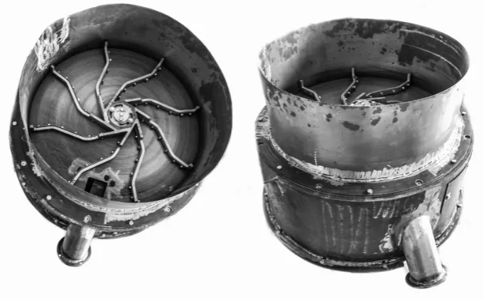
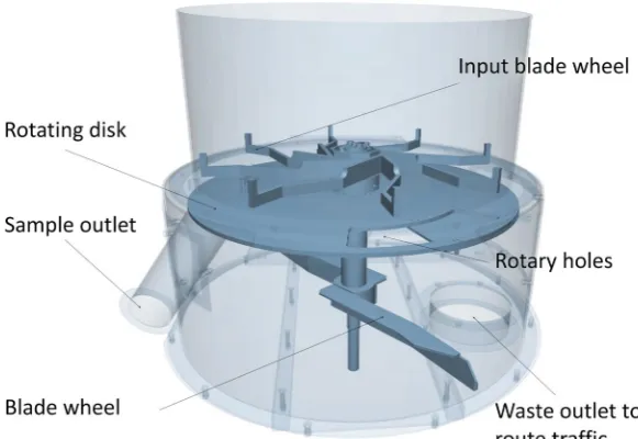
Experiments were performed on a realistic sample divider model. The overall outside diam-eter of the equipment is 0.86 m and the height is 0.75 m. There are three main functional parts. The first and top part is the inlet part. Here, material enters onto the blade wheel, which evenly distrib-utes the input material. From this space with the blade wheel with one opening, which is static in relation to the blade wheel, the material travels to the centre (second) section. Here there is a rota-tional disc, which is connected by a shaft to the blade wheel at the entry into the equipment. This rotating disc has symmetrically located holes, which rotate together with the disc. The material falls through the rotating holes in the disc either into the outlet for sampling or into the third
bot-tom section. This part also contains a blade wheel which ensures regular output of material from the equipment back to the transport route. This blade wheel is also connected by a shaft with the blade wheel at the equipment inlet. The outlet from the equipment for sampling is located directly under the static opening of the first part. A disc with openings rotates between the static opening and the outlet for sampling. At the moment when the opening of the rotating disc between the equip-ment outlet for sampling and the static opening of the first part coincide, material falls from the first part into the sampling outlet, and a sample is taken. The experimental equipment is shown in Figure 1 and the 3D model in Figure 2.
During experiments the speed of the sampling equipment was set to 29 rpm. A total of 10 kg of brown coal was fed into the equipment continual-ly. The filling process took 40 s. This corresponds to a fed quantity of 0.25 kg·s-1. Filling of the sampling equipment was provided by a controlled belt conveyor. At both outlets from the sampling equipment the quantity of material in kg was de-tected, which changed in time. Detection of the weight was performed using strain gauge scales, which were connected to a laptop via a DS-NET measuring card.
The 3D model of the sampling equipment was created according to the dimensions of the realis-tic experimental equipment using CAD software. This model was imported into the EDEM Aca-demic simulation program in *.STL format. The parameters used for material geometry and parti-cles are shown in Table 1 and Table 2. Simulation
experiments were performed using a 3 mm parti-cle diameter. The partiparti-cle density was determined experimentally using EDEM Academic. This was based on the realistic experiment, where a cylin-der (0.1185 m diameter and 0.197 m height) was filled with a sample of coal and weighed. This experiment was repeated several times and an average sample weight of 1.712 ± 0.013 kg was determined for a volume of 0.0022 m3. The same cylinder was filled in the DEM and the material particle density was changed so as to achieve the required level height in the measuring cylinder, while maintaining a total sample weight of 1.712 kg. The shear modulus of particles was selected at a minimum value with respect to the calcula-tion time of the simulacalcula-tion. The coefficient of static friction for the particles was selected based on measurement of the effective angle of internal friction of a coal sample using the RST-01 shear
machine. The coefficient of static friction between particles and the geometry were selected based on measurements made on the Jenike shear machine.
The profile of weight curves in time from both sampling equipment outlets in the DEM simula-tion was obtained using the Selecsimula-tions-Geometry Bin function (Figure 3). These selections detect the increase in particle weight in time. These values were exported to tables and graphs were plotted. The outputs from the realistic experiment were processed using DEWESoft 7.0 software. Weight values in 5 s time intervals were select-ed to consolidate and compare outputs from the DEM and DEWESoft.
RESULTS AND DISCUSSION
Firstly, experiments were performed on the realistic equipment. Ten experiments of filling and emptying were performed on the sampling equipment. Figure 4 shows a record of ten mea-surements together with the average value at the waste outlet from the sampling equipment. Figure 5 shows a record of ten measurements at the sam-pling outlet together with the average value.
The average weight value from the realistic experiment at the waste outlet was 8.68 ± 0.05 kg and 1.18 ± 0.02 kg at the sampling outlet. During one experiment an average of 9.86 kg coal passed through the equipment. The difference from the ten kilograms at the inlet is 0.14 kg on average. This value can partially be considered an error of the strain gauge scales. Furthermore, each time Table 1. Material properties
Input parameter Geometry Particle
Poisson‘s Ratio (-) 0.3 0.25
Shear Modulus (Pa) 8.077e+10 1e+06
Density (kg·m-3) 7800 1650
Table 2. Contacts parameters
Input parameter Geometry-Particle Particle-Particle
Coefficient of Restitution (-) 0.5 0.4
Coefficient of Static Friction (-) 0.32 1
Coefficient of Rolling Friction (-) 0.1 0.01
Advances in Science and Technology Research Journal Vol. 12 (1), 2018
a different quantity of material remained in the equipment, part of the fine fraction dusted off, or settled on the equipment’s internal parts.
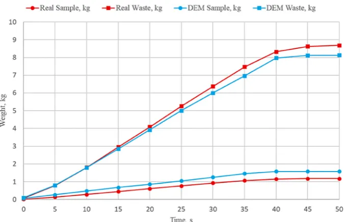
Figure 6 shows a comparison of the realistic experiment and DEM simulation. The weight of the material at the waste outlet of the dividing equipment in the DEM simulation was 8.13 kg. The weight of material at the sampling outlet in the simulation was 1.58 kg. It is evident that the measured values differ between the simulation and realistic experiment. More measurements were performed in the realistic experiments.
Be-sides the set of ten measurements in Figures 4 and 5, a starting measurement was also performed. The conduct of this measurement is more similar to the DEM simulation. Prior to measurement the sampling equipment was emptied and cleaned. There was no residual material in the equipment from previous measurements. A weight of 7.89 kg was measured at the waste outlet and 1.02 kg at the sampling outlet of the sampling equipment. Theoretically, 1.09 kg remained in equipment. These values differ more compared to the simu-lation than in the case of average values from Fig. 4. Result from ten experimental measurements of weight at the waste outlet from the equipment
ten measurements. The differences in compar-ing results from simulations and realistic experi-ments may be the result of the differences in the realistic experiment model and ideal 3D model. The 3D model does not contain all the geomet-ric differences such as, for example, clearances or asymmetric arrangement of individual parts. The achieved results for these first validation experi-ments on the sampling equipment can be consid-ered positive. Based on these results we can con-tinue to optimize the 3D model and calibration of DEM simulation.
CONCLUSIONS
This task focused on the first testing valida-tion of flow of material through the sample di-vider. Experimentally determined input param-eters were used for the EDEM Academic applica-tion, such as density and friction parameters. The achieved results will be used primarily for further detailing of the simulation and calibration. Cali-bration will also be necessary for other modes be-sides just setting the 29 rpm speed. Validation can be improved by modification of material density, Fig. 5. Result from ten experimental measurements of weight at the sampling outlet from the equipment
Advances in Science and Technology Research Journal Vol. 12 (1), 2018
particle moisture, change in speed, and others. Furthermore, attention must be paid to the possi-ble differences between the realistic and 3D model of the sampling equipment. This task will be part of further research and study of impacts on the resultant validation of the sampling equipment.
Acknowledgements
This paper was conducted within the frame-work of the project LO1404: Sustainable devel-opment of ENET Centre.
REFERENCES
1. Freidina E. V., Botvinnik A. A. and Dvornikova A.
N. Basic principles of coal classification by use -ful quality. Journal of Mining Science, 47(5), 2011, 593–605.
2. Freidina E. V., Botvinnik A. A. and Dvornikova A. N. Coal quality control in the context of interna-tional standards ISO 9000–2000. Journal of mining science, 44(6), 2008, 585–599.
3. Yang X. and Teng F. The air quality co-benefit of
coal control strategy in China. Resources, Conser-vation and Recycling, 129, 2016, 373–382. 4. Sun D., Fang J. and SUN J. Health-related benefits
of air quality improvement from coal control in Chi-na: Evidence from the Jing-Jin-Ji region. Resources, Conservation and Recycling, 129, 2018, 416–423. 5. Zhu Q. Coal sampling and analysis standards. IEA
Clean Coal Centre, London, United Kingdom, 2014. 6. Owen P. J. and Cleary P. W. Prediction of screw
conveyor performance using the Discrete Ele-ment Method (DEM). Powder Technology, 193(3), 2009, 274–288.
7. Guo Y., Wang S., Hu K. and Li D. Optimization and experimental study of transport section lateral pressure of pipe belt conveyor. Advanced Powder Technology, 27(4), 2016, 1318–1324.
8. Orefice L. and Khinast J. G. DEM study of granular transport in partially filled horizontal screw con -veyors. Powder Technology, 305, 2017, 347–356. 9. Ramírez-Aragón C., Alba-Elías F.,
González-Marcos A. and Ordieres-Meré J. Segregation in the tank of a rotary tablet press machine using ex-perimental and discrete element methods. Powder Technology, 328, 2018, 452–469.
10. Syed Z., Tekeste M. and White D. A coupled slid-ing and rollslid-ing friction model for DEM calibration. Journal of Terramechanics, 72, 2017, 9–20. 11. Horabik J. and Molenda M. Parameters and contact
models for DEM simulations of agricultural granu-lar materials: A review. Biosystems Engineering, 147, 2016, 206–225.
12. Liu X., Hu Z., Wu W., Zhan J., Herz F., Specht E. DEM study on the surface mixing and whole mix-ing of granular materials in rotary drums. Powder Technology, 315 ,2017, 438–444.
13. Zhu H. P., Yu A. B. and Wu Y. H. Numerical
inves-tigation of steady and unsteady state hopper flows.
Powder Technology, 170(3), 2006, 125–134. 14. Calderón C. A., Olivares M. C. V., Uñac R. O. and
Vidales A. M. Correlations between flow rate pa -rameters and the shape of the grains in a silo dis-charge. Powder Technology, 320, 2017, 43–50. 15. Mondal D. and Ghosh N. Study on filling factor
of short length screw conveyor with flood-feeding
condition. Materials Today: Proceedings, 5(1), 2018, 1286–1291.
16. Fedorko G., Molnar V., Grincova A., Dovica M., Toth T., Husakova N., Taraba V. and Kelemen M. Failure analysis of irreversible changes in the con-struction of rubber–textile conveyor belt damaged by sharp-edge material impact. Engineering Fail-ure Analysis, 39, 2014, 135–148.
17. Molnar V., Fedorko G., Stehlikova B., Michalik P. and Weiszer M. A regression model for prediction of pipe conveyor belt contact forces on idler rolls. Measurement, 46(10), 2013, 3910–3917.
18. Fedorko G., Molnar V., Dovica M., Toth T. and Kopas M. Analysis of pipe conveyor belt damaged by thermal wear. Engineering Failure Analysis, 45, 2014, 41–48.
19. Molnar V., Fedorko G., Stehlikova B. and
Pau-likova A. Influence of tension force asymmetry on
distribution of contact forces among the conveyor belt and idler rolls in pipe conveyor during trans-port of particulate solids. Measurement, 63, 2015, 120–127.
20. Klepka T., Dębski H. and Rydarowski H. Charac -teristics of high-density polyethylene and its
prop-erties simulation with use of finite element method.
Polimery, 54(9), 2009, 668–672.
21. Fedorko G., Molnar V., Dovica M., Husakova N., Kral J. jr. and Ferdynus M. The use of
indus-trial metrotomography in the field of maintenance
and reliability of rubber-textile conveyor belts in closed continuous transport systems. Eksploatacja I Niezawodnosc – Maintenance and Reliability, 18(4), 2016, 539–543.
22. Jachowicz T. and Sikora R. Methods of forecasting of the changes of polymeric products properties. Polimery, 51(3), 2006, 177–185.
23. Rackl M., Top F., Molhoek C. P. and Schott D. L. Feeding system for wood chips: A DEM study to improve equipment performance. Biomass and Bioenergy, 98, 2017, 43–52.
24. González-Montellano C., Ramirez A., Gallego E. and Ayuga F. Validation and experimental calibra-tion of 3D discrete element models for the