39 Available online at www.ijiere.com
International Journal of Innovative and Emerging
Research in Engineering
e-ISSN: 2394 - 3343 p-ISSN: 2394 - 5494
PFC Boost Topology Using Average Current Control Method
Gemlawala Samarth M., Prof. Dimple Bhanabhagvanwala
Sarvajanik College of Engineering & Technology, Dr R K Desai Marg , Athwalines, Surat , Gujarat , India
ABSTRACT:
Now a days various power converters like AC-DC or DC-DC are widely used due to their flexible output voltage and high efficiency. But these converters takes the current in the form of pulses from the utility grid so that the high THD and poor power factor are the major disadvantages of these converter. Commonly these converters are used in various electronic equipments and they are aimed to control the output voltage even in the variation of load current and input voltage. Currently, there is increasing demands of low THD in current drawn from the utility and high power factor. There is a requirement of good power quality so that important efforts have been made for the developments of the Power Factor Correction converters. The boost converter is broadly used as Power Factor Correction converter because of its simplicity and efficiency. The boost Power Factor Correction converters are combination of a full bridge AC to DC diode rectifier and a boost converter. The bridge rectifier offers high conduction losses which lowers the system efficiency. A rectifier with the boost PFC topology has been analysed to improve the power factor and reduces THD in input current. Here, Average current control method has been analysed by using MATLAB Simulink.
Keywords: THD; power quality; power factor; boost converter; MATLAB
I. INTRODUCTION
The power converters usually have some power conversion stages where the operation of these stages is decoupled on an instantaneous basis by inductors and capacitors which means of energy storage elements. Therefore the instantaneous power output does not equal to the instantaneous power input. Thus the basic module of power electronic systems is a power converter. It utilizes power semiconductors devices controlled by integrated circuits (IC) and possibly energy storage elements i.e. inductors and capacitors. Most electronic equipments are supplied by 50Hz or 60Hz utility power supplies. Almost in all of the equipments power is processed through some kinds of power converters such as AC-DC or DC-DC or DC-AC. Rectifiers i.e. AC to DC power converters are typically used in SMPSs (switch-mode power supplies), ASDs (adjustable-speed drives), UPSs (uninterrupted power supplies), power provisions for communication system equipments, test equipments etc[1].
Almost all power supplies have input bridge rectifier followed by a large filter capacitor. The current drawn by these devices are in the form of pulses from the AC mains. These pulsating current have fundamental and odd harmonics [1][8]. But this harmonic produces problems for the power distribution systems. Moreover, the losses are causes due to the harmonic content in the pulsating current. It creates dielectric stresses in capacitors and power distribution cables. As the power factor become poor the distribution current become higher[1][4].
If there is no power factor correction circuit in the input rectifier with a capacitive filter draws pulsating currents from the utility grid[1][4][8]. So the power quality become poor and the higher harmonic contents in the power creates bad affect to other users fed from same grid. Higher harmonics in the current affects the utility grid and other users appliances as well.
Passive filters i.e. inductor in the input circuit can be used to improve the power factor. If the inductor value is chosen to be high then it stores much energy which keeps the rectifier on throughout the half cycle. As a result it reduces the harmonic contents mainly caused by discontinuous conduction of rectifiers. In passive power factor correctors the size of inductor is big and bulky because they are operated at the frequency of the ac mains. An effective passive filter minimizes harmonics in the current and improves the power factor. But it does not solve the problem completely. So that the active power factor correction method has been developed[1].
Generally accepted method to correct the poor power factor of electronic power supplies by using active approach method. The method has both active filters like shunt, series and hybrid active filters and Power Factor Correction circuits like boost, buck, fly back converters. An active filter improves the quality of power by eliminating current harmonics [1][4][8]. It can sense the nonlinear load current and voltage waveforms so that the input supply current can be easily regulated. Active filters are much expensive and also need some complicated control circuit therefore they are generally used in high power three phase power systems.
40
different kind of topology and control process has been developed and evaluated to make the power quality better and improved power factor. In this paper, use of PFC boost topology to improve the power quality and average current control method has been shown to reduce power factor at lower level and also the total harmonic distortion.
II. NONLINEAR LOAD AND IT’S EFFECT
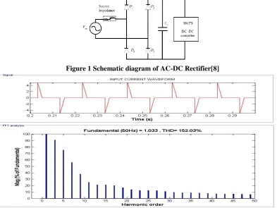
The power can be obtain from the utility power grid in different ways. Almost all of the electronic equipments connected to the utility power grid draws high peak discontinuous non-sinusoidal line current rather than smooth sine wave current. This current contains the number of harmonic currents, which flows through utility power grid as well as in the equipment itself. Figure 1 shows the illustration of simulation of single-phase alternating current-direct current (AC-DC) bridge rectifier followed by bulk capacitor. The schematic of single-phase bridge rectifier shown in Figure 1 has been simulated in MATLAB simulink. The converter shown in Figure 1 draws a discontinuous non-sinusoidal peak current and hence there is a presence of harmonic in current of the AC-DC rectifier circuit as well as in the utility power grid to which this converter is connected. The diodes conduct only when instantaneous input voltage is greater than the output voltage so that the narrow peak input current occurs due to the short on-time duration of bridge rectifier diodes. Table 1 shows the specification and component values of the AC-DC rectifier circuit. The results obtained from the simulation are shown in Figure 2, which shows the input line current waveforms of supply frequency 50 Hz. Figure 2 represents the harmonic spectrum of the line current.
Table 1 Specification and components used in simulation of figure 1 SR.
NO. PARAMETER VALUE
1. Input voltage(VAC) 40 V(RMS)
2. Output Voltage(V0) 100 V
3. Load 100 Ω
4. Co 1000 µF
A conventional AC-DC bridge rectifier with bulk capacitor has following main drawbacks: It generates harmonics and electromagnetic interference (EMI) in the power grid. It has low PF which results in reduced efficiency of the system.
It increases the operating temperature in the transmission lines as well as in the other equipments connected to the grid.
It reduces the capacity of line to provide a maximum power to the load.[8]
Thus, in order to overcome the above mentioned drawbacks of a converter, it is essential to improve the power factor of a system.
Figure 1 Schematic diagram of AC-DC Rectifier[8]
41
III.PFCBOOST TOPOLOGY WITH CONTROL SCHEME
AC to DC power conversion with power factor correction works to high frequency and it has the input current drained from AC mains which is sinusoidal and in phase with AC voltage. A power factor correction pre regulator is interposed between AC main and DC load. In this way, nonlinear loads appear to the AC line as a resistive loads. There are many topologies that can be used for power converter. The most popular topology for power factor correction pre regulator is the boost converter. Any topologies can be used for PFC pre-regulators, but the most common are fly back converter, SEPIC converter, Cuk converter, etc. [1]-[4]. In this paper boost converter has been taken into consideration.
There are different control methods, among which any one method can be used in PFC application. In general, for any control strategy for PFC, two basic feedback compensating loops are required [4], shown in figure 3. A outer loop is known as voltage feedback compensating loop is used to keep the bus voltage to a fixed DC (predefined reference) value [4]. An inner loop is known as current loop is used to control the inductor current to a specific level and to shape the inductor current with the aim to be as alike as possible to the rectified input DC voltage keeping almost unity Power Factor,[4]. The PFC power supplies with control loops implementation is employed to achieve a stable system with a tolerable dynamic behavior irrespective of the system loading conditions [4]. In this paper boost converter topology using average current control method has been taken into consideration.
Figure 3 Principle of control scheme of PFC boost
Each control method has its own advantages and disadvantages based on the topology of the DC-DC converter employed in PFC converter. Now a day's average current control method is taken as a standard strategy in the industry for the boost AC-DC PFC converter, since it has advantages of less THD with improved noise and easy to shape input current waveform.[8]
This control method allows a better improved input current waveform. A current error amplifier is there as in the figure 4, which filters the inductor current sensed. The output of the current error amplifier drives a PWM modulator. The inner current loop tends to reduce the error between the average input current, ig and its reference. The latter is obtained as the
peak current control. Same considerations can be realized with respect to this control technique because the converter works in a continuous inductor current mode. This method overpowers the complications of the peak current control method by introducing a high gain integrating current error amplifier (CA) into the current loop[4].
Advantages:
Constant switching frequency; No need of compensation ramp;
Control is less sensitive to commutation noises, due to current filtering[4] Disadvantages:
Inductor current should be sensed;
A current error amplifier is needed and its compensation network design must take into account the different converter operating points during the line cycle.
42 Figure 5 Average current control waveform[4]
IV.SIMULATION RESULT
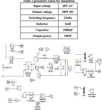
The power factor correction technique using average current control is simulated by using MATLAB simulink software nd the results obtained are shown below. The values taken in the simulation circuit are given in the table 2.
Table 2 parameter taken for simulation
Input voltage 40V AC
Output voltage 100V DC
Switching frequency 21kHz
Inductor 3mH
Capacitor 1000µF
Output power 100W
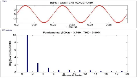
43 Figure 7 Input current waveform and FFT analysis of boost PFC using Average current control
Figure 8 Output voltage waveform of boost PFC using Average current control
44
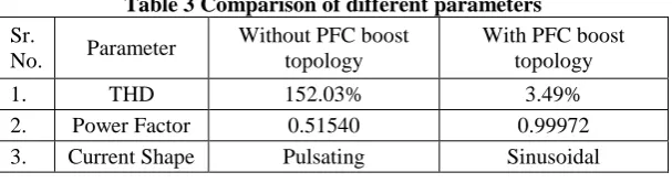
V. COMPARISON OF RESULTS
Table 3 Comparison of different parameters Sr.
No. Parameter
Without PFC boost topology
With PFC boost topology
1. THD 152.03% 3.49%
2. Power Factor 0.51540 0.99972
3. Current Shape Pulsating Sinusoidal
VI.CONCLUSION
In this paper, the analysis of circuit with and without PFC boost topology is shown. In the open loop rectifier i.e. without PFC boost topology, there is a phase difference between input voltage and current and also the THD is very high. In the close loop i.e. with PFC boost topology we can remove the lower order harmonics, hence we can achieve the power factor nearer to unity, THD less than 5%.
ACKNOWLEDGMENT
First and foremost, all gratitude to the omnipresent god for giving me the strength through my prayers and to plod me on despite the difficult situations I passed through till my graduation. I would like to express my gratitude towards my supervisor Prof. Dimple Bhanabhagvanwala, for his cooperation, guidance, inspiration, and valuable advices while doing this project. In addition, I sincerely thank all the lecturers who have taught me, for the lessons that have been delivered and the morals the have been gained. Not to forget mentioning my fellow friends, I would like to thank them for sharing useful ideas, information and moral support during the course of study. Last but not least, I would like to express my love, gratitude and appreciation to my beloved parents and brothers for their love, patience, support and encouragement they provide during my study.
REFERENCES
[1] K. Mahmud and Lei Tao, "Power factor correction by PFC boost topology using average current control method", 2013 IEEE Global High Tech Congress on Electronics, 2013.
[2] S. Sahoo and H. Jariwala, "A new power factor correction technique using PFC boost converter", 2012 11th International Conference on Environment and Electrical Engineering, 2012.
[3] H. Kim, G. Seo, B. Cho and H. Choi, "A Simple Average Current Control With On-Time Doubler for Multiphase CCM PFC Converter", IEEE Transactions on Power Electronics, vol. 30, no. 3, pp. 1683-1693, 2015.
[4] L.Rossetto, G.Spiazzi, P.Tenti,” Control Techniques For Power Factor Correction Converters” Proc. PEMC’94-9 [5] F. Musavi, M. Edington, W. Eberle and W. Dunford, "Control Loop Design for a PFC Boost Converter With Ripple
Steering", IEEE Transactions on Industry Applications, vol. 49, no. 1, pp. 118- 126, 2013.
[6] W. Cheng, J. Song, H. Li and Y. Guo, " Time-Varying Compensation for Peak Current-Controlled PFC Boost Converter", IEEE Transactions on Power Electronics, vol. 30, no. 6, pp. 3431-3437, 2015.
[7] “IEEE 519 Recommended Practices and Requirements for Harmonic Control in Electric Power Systems,” Tech. Rep., IEEE Industry Applications Soc./Power Engineering Soc., 1993.