International Journal of Engineering
J o u r n a l H o m e p a g e : w w w . i j e . i rReceding Horizon Based Control of Disturbed Upright Balance with Consideration of
Foot Tilting
B. Miripour Fard*a, A. Bagheri b, A. S. Khoskbijarib
a Department of Robotics Engineering, Hamedan University of Technology, Hamedan, Iran.
b Department of Mechanical Engineering, the University of Guilan, Rasht, Iran.
P A P E R I N F O
Paper history:
Received 08 February 2013
Received in revised form 24 March 2013 Accepted 18 April 2013
Keywords:
Hybrid Model
Receding Horizon Approach Upright Balance
External Disturbances
A B S T R A C T
In some situations, when an external disturbance occurs, humans can rock stably backward and forward by lifting the toe or the heel to keep the upright balance without stepping. Many control schemes have been proposed for standing balance control under external disturbances without stepping. But, in most of them researchers have only considered a flat foot phase. In this paper a framework that includes the foot tilting is presented. This is done by hybrid modeling of the humanoid robot and also using a receding horizon based approach. The decision for the recovery pattern is done based on the evaluation of the Vertical Forces criterion. If the method predicts the tilting of the foot under disturbance, then the optimum trajectories are obtained for upper segments to return the robot to the secure posture in which the foot is flat (home posture). The obtained optimum trajectories are then tracked by a feedback controller. In the context of receding horizon approach the Extrapolated Center of Mass position has been used as the stability constraint. The results demonstrate the success of method to reproduce human-like balance recovery reactions under impulsive disturbances. The simulated results are compared with experimental data reported in the biomechanics literature.
doi: 10.5829/idosi.ije.2013.26.10a.14
1. INTRODUCTION 1
In everyday life we see that humans are capable of rejecting many disturbances which may cause them to fall. They evoke proper strategies against perturbations and then behave in an agile manner to recapture postural balance. For a long time, it has been the goal of roboticists to create humanoids having human levels of competence in perceiving, thinking and acting. Studying of human reaction patterns to sudden external disturbances is still an open area of research and a lot of researches are dedicated to it in order to develop robust controls for humanoids.
From the literature of biomechanics it is now clear that human evoke ankle and hip strategies (or a combination of the two) to keep upright balance without stepping during external or internal disturbances. Ankle strategy is used to deal with small disturbances, with a compensating torque at the ankle joint. As the disturbance increases, the human uses more of its upper
*Corresponding Author Email: [email protected] (B. Miripour Fard)
body by bending in the hips, i.e., with the hip strategy to maintain balance. In biomechanics, these strategies have been studied extensively, both experimentally and through simulations, under quiet stance and in response to large spectrum of disturbances [1-5]. If the disturbance is too large, the human can avoid falling by taking a step. Study of balance recovery under larger disturbances which leads stepping has been much less explored. In the current paper we will not consider stepping. For a review of balance recovery by stepping see [6].
In robotics, several researchers have attempted to use human-inspired control strategies for standing balance control of bipeds under external disturbances. In spite of many research efforts, little success has been achieved so far [7]. The main difficulty comes from the constraint between the feet and the ground which is an unilateral constraint [8]. Gorce [9] has addressed the balance recovery of robot subjected to an unexpected external impact force while standing upright via a hierarchical control structure. His controller includes a coordinator level with optimization capability based on the Simplex method. Abdallah and Goswami [10]
proposed a two-phase strategy for balance recovery under unexpected environmental forces and applied it to a planar four-link biped. The first phase, called the reflex phase, is designed to withstand the immediate effect of the external force. The second phase is the recovery phase where the system is steered back to a statically stable home posture. Nenchev and Nishio [11] implemented ankle and hip strategies for balance control of small humanoid HOAP-2 using simple dynamical models including virtual spring-dampers. They have shown that the impact acceleration data, measured during posture perturbation, can be used to invoke one of the two strategies, depending on the experimentally determined threshold.
Liu and Atkeson [12] have focused on upright balance control using trajectory library method which can handle instantaneous and continuous disturbances. Tahboub [13] introduced biologically inspired humanoid postural control architecture to deal with external disturbances and investigated its performance experimentally on PostuRob humanoid. His proposed architecture is composed of disturbance estimation and compensation mechanisms. He used two estimation mechanisms; Kalman filter for orientation and extended observer for external forces. The disturbances were compensated directly by applying a counter torque.
Lee et al. [14] have used a biomechanically motivated approach that uses the rate of change of the angular momentum about the center of mass (CoM) to improve the balance of a humanoid robot when standing, walking, and running. They used receding horizon viability radius (RHVR) method to predict the rate of change of angular momentum generated in CoM and considered three stability strategies based on the amount of disturbance. Kanamiya et al. [15] have suggested a method for implementing the ankle and hip strategies when an unknown continuous external force is applied to a humanoid robot. They obtained compliant response to disturbance by attaching a virtual spring-damper in an appropriate way for each strategy. Stephens [16] analytically described the stability of certain push recovery strategies using simple models of the robot dynamics. Analytic relationships can be used to determine which strategies should be evoked based on the current state of the robot. Vukobratovic et al. [17] developed and realized a simulator tool for dynamic analysis of human-or-humanoid behavior under disturbances. They comparatively analyzed the robustness of some postures to external disturbances using feed-forward plus feedback control and also integral control. Naderi et al. [18] used predictive dynamic method to obtain human like motions for upright balance of a biped robot under external disturbances. They also proposed the Vertical Forces criterion. An appropriate estimation of the motor planning criterion of the human for disturbance
rejections is obtained by using the Vertical Forces criterion as a stability constraint [19].
In most of the works done on the balance control of perturbed upright stance so far, researchers have attempted to produce human like strategies with consideration of flat foot phase. While, in some situations the human can keep the balance by lifting the toe or the heel without stepping. In this situations, ZMP reaches to the border of base of support and the biped is about to lose the controllability. This posture is very challenging for bipeds balance, because there is no actuation between the unilateral contacts of the feet with ground. In this situations, it seems human mostly uses the dynamics of its upper segments in a deliberate manner to keep the balance. Some researchers have considered a toe and a heel joint for foot and have investigated its effect in natural walking and balancing [20, 21]. In most of these studies it is also considered that at least one point of the toe-link (the tip of the toe) and one point of the heel-link (the end of the heel) are in contact with the ground. Although, the torque applied on the toe-joint can help to keep balance in standing, but its amount is not substantial. It seems that after tilting of the foot due to a disturbance, the dynamics of upper body plays important role to recapture entire balance and bring the whole body to the stable posture (flat foot phase). In best of our knowlage, Sobotka's work [22], is closely related to present work dealing with modeling. He has developed a periodic trajectory planning method using a hybrid dynamical systems approach and controlled the system using the computed torque method.
To summarize, in the previous works much less attention has been paid to the control of upright standing with consideration of foot tilting. So, the aim of the current work is to address this issue and obtain a human-like balance recovery pattern under disturbances. The reference trajectory of the controller is designed based on a receding horizon scheme which regards current and future states of the model and also constraints on the stability. Tilting of the foot is predicted using the Vertical Forces criterion.
In the following section, the model of the biped is described and its dynamic equations are derived. The control strategy is detailed next and then the simulation results are discussed. Finally, concluding remarks are drawn.
2. HYBRID MODELING
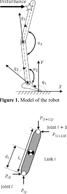
Figure 1. Modelof therobot
Figure 2. Free body diagram showing impulsive forces applied on the link i
All actuated joints are assumed as frictionless hinges that are independently actuated. Each parameter of the segments such as length, mass, center of mass, and moment of inertia is selected based on average anatomical proportions [23]. It is considered that the feet can tilt. Tilting is defined as a free rotational movement around one foot edge. The amount of coefficient of friction is considered as much as to prevent slippage. It is also assumed that the base of support is rigid and flat.
A hybrid (continuous-discreet) modeling framework [24] has been chosen, because the dynamical description when the foot is tilted differs from the dynamical description when the foot is flat. Moreover, impulsive disturbances lead to an instantaneous discontinuity in the state of the model.
In the absence of disturbance, dynamic equations of the model is easily derived using Lagrange’s formulation considering the model as a two or three link planar open chained manipulator robot. During the flat foot phase there are only two DOF (q=[q2,q3]T) with two
actuators [u2,u3]T while in the foot tilted phase there are
three DOF (q=[q1,q2,q3]T ) with the same number of
actuators. The mathematical model, describing the biped sagittal motion, is as follows
u B q
G q q q N q q
M( )]n n [ ( , )]n n [ ( )]n1 [ ]n 2
[ ´ &&+ & ´ &+ ´ = ´ (1)
in which q is the vector of generalized coordinates depicted in Figure 1, M(q) the mass-inertia matrix,
) , (q q
N & contains the centrifugal and Coriolis forces, G(q) the vector of gravitational forces, u=[u2,u3]T the
vector of control inputs and B a torque distribution matrix. During the flat foot phase, n=2 and after foot tilting, n=3. The set (q,q&) constitutes the state of the model. The state trajectories are continuous until discontinuities occur when
· an impulsive disturbance applied;
· the foot starts tilting or stops tilting (landing).
2. 1. Discontinuity due to Impulsive Disturbance
Disturbance can be considered as a force applied for an infinitesimal period of time (impulse) or a force applied for a finite duration of time (continuous force). In this paper, the disturbance is considered as an unexpected impulsive forceapplied on the end of torso. We suppose the model has the capability to detect the disturbance instant. Equations are derived using the Newtonian approach by applying the principles of linear and angular impulse and momentum. The basic assumptions are:
a) the disturbance takes place over an infinitesimally small period of time;
b) impulsive disturbance results in an instantaneous change in the velocities of the generalized coordinates, but the positions remain continuous; c) the torque supplied by the actuators is not
impulsional.
It is assumed that the disturbance occurs during quiet standing in which the foot is flat. Therefore, the equations are derived for a two link model. The free-body diagram of the link is shown in Figure 2.
The impulse and impulse moment equations [25] for link i can be written as:
X i iX i i i i
j
j j j
i l q q d q q p p
m ( 1)
1
1
] ) cos( )
cos(
[ +
-=
-= D +
D
å
& &y i iy i i i i
j
j j j
i l q q d q q p p
m ( 1)
1
1
] ) sin( )
sin(
[ +
-=
-= D
-D
å
& &-+
-=
D i (i+1)X(i i)cos( i) iX icos( i) i q p l d q p d q
I &
). sin( )
sin( ) (
) 1
(i y li di qi piydi i
p + - + q
(2)
where mi, li,Ii and di are the mass, the length, the inertia and the center of mass of link i, respectively.
ix
p and piy are the horizontal and vertical components
the angular velocities of the link i just before and after disturbance, respectively. A set of equations (Equation (2) for i=1, 2) have been solved to obtain q&i+. It should be noted that p3x and p3y are the horizontal and
vertical components of impulsive disturbance exerted on the end of HAT, respectively.
To summarize, the map of impulsive disturbance which relates the state just after disturbance to state just before disturbance can be presented as follows:
÷ ÷ ø ö ç ç è æ D = ÷ ÷ ø ö ç ç è æ
-+ +
q q q q q
&
& ( ) (3)
2. 2. Discontinuity due to Foot Tilting To identify
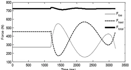
and predict the foot tilting after impulsive disturbance, it is necessary to use a decision making criterion. In this study, the mathematical conditions for making decision (a discrete switch) are modeled using Vertical Forces criterion [18]. To use the Vertical Forces criterion, it is necessary to assume that the reaction forces between the feet and the ground are concentrated forces applying on the two extremities of the plantar arch (see Figure 3).
Based on the Vertical Forces criterion, if one of the vertical forces under the toe or the heel approaches zero, the foot is about to tilt. When the disturbance is strong and prediction shows that the feet will start to tilt, proper reactions should be adopted in actuated joints (upper limbs) so that both the vertical forces under the toe and the heel take a nonzero and positive values. This ensures that the model will be back to the secure posture (flat foot phase). The vertical forces can be obtained by solving the dynamic equilibrium equations of the foot (Figure 4):
(
)
;1
2 21
21ya x f f c
f
heel l f l f h u m gl
f = - - + +
(
( ))
;1
2 21
21y f a y f f c
f
toe f l l f h u m gl l
f = - - + - + (4)
Figure 3. Position of the point of application of the resultant vertical forces acting on the posterior (Fheel) and anterior (Ftoe) parts of the plantar arch
Figure 4. The free body diagram of the foot
The amount of vertical forces is constantly checked on a crossing to zero. If one of them approaches zero, the switching between models should be done. It should be noted that after foot rotation, a change of coordinates is also necessary to reinitialize the model with the new governing equations.
2. 3. Overall Model: Hybrid System The hybrid
model combines the equations of motion for two models (Equation (1)), and re-initialization rule caused by the impulsive disturbance. Transitions between situations are assumed to be instantaneous. The hybrid state vector
x is introduced as the combination of the continuous state x=
[
q q&]
T and the discrete stated
x . The discrete state xd codes the events. The hybrid state is:
[
]
Td T x x
=
x
Two categories of events, impulsive disturbance event and foot tilting event should be distinguished. In the state space representation, the model can be represented as:
{
ï î ï í ì
ïî ï í ì
Î Î Ï +
=
-2 1 2 1
tilting foot ) (
e disturbanc )
( Discrete
, ,
) ( ) ( Continuous
S b
S a
S S u g f
x x x x x x&
(5)
where S1 and S2 are switching surfaces. In numerical simulations, the instants of impulsive disturbance (switching surface S1) is determined manually. Foot tilting is initiated when a vertical force approaches zero
} 0 ) ( or 0 ) ( | {
2= x- ftoe x- = fheel x- =
S (6)
3. CONTROL STRATEGY
· Recovery without tilting of the foot (flat foot phase)
· Recovery with foot tilting
When a disturbance occurs, first the robot tries to keep the balance while the foot is flat. Vertical forces are evaluated in a prediction horizon to predict the tilting of the foot. In the first case, which is invoked against small disturbances, the model is considered as a fully actuated two degrees of freedom system. Desired trajectories are obtained for the ankle and the hip joints using the receding horizon approach for finite time duration and then the computed torque control is used to track the desired trajectories.
In the second case, the model is considered as an under-actuated three degrees of freedom system. The main idea in the control design is the choice of particular reference trajectories for the actuated joints to be tracked by the feedback controller in order to return the foot to the flat posture which is a secure situation. In the better words, in the case of strong disturbances that the model can maintain balance by going on the toe (or the heel) without need to stepping, the dynamic of two actuated joints should be exploited to recover the balance of the entire system.
3. 1. Recovery without Tilting of the Foot In this
case, there are two degrees of freedom that proper reference trajectories should be designed for them. Consider a control sampling period tc>0 such that
p c
f N
t /t = . tf is recovery duration and Np represents prediction horizon. The following notation is used to refer to decision instants on the interval
[
t0 tf]
} 1 , , 0 { ;
0+ Î
-= c p
j t jt j K N
t
In order to generate the reference trajectories, a derivable continuous p-parameterized polynomial function is defined as:
å
= = 6 0 ) ( ) ( i i j i j p pT t a t (7)
with the following constraints:
;
0; ( )
)
( j p f f
p q T t q
T t = =
f f p p q t dt dT q t dt dT & & = = ; ( ) )
(0 0
f f p
p t q
dt T d q t dt T d & & & & = = ; ( ) ) ( 2 2 0 0 2 2 0 )
(p =
Tp
(8)
Parameter p should be obtained by an optimization procedure explained later. The parameterized trajectories of the ankle and the hip joints (q2 and q3) are:
å
= = 6 0 2 22( ) ( )
i i j i j p p
T t a t
å
= = 6 0 3 33( ) ( )
i i j i j p p
T t a t
(9)
Based on the computed torque method, one can write:
) , ( ) ) ( ( ) ) ( ( 2 ) ( 2 2 2 2 2 2 2 2 2 2 2 p H q T q dt dT dt T d q j j j p j j p j p j t t l t l t = -= & & & ) , ( ) ) ( ( ) ) ( ( 2 ) ( 3 3 3 3 2 3 3 2 3 2 3 p H q T q dt dT dt T d q j j j p j j p j p j t t l t l t = -= & & & (10)
Using Equation (1) and by two succesive integrations of the above relations , predicted values of the angular trajectories can be obtained as:
ò
ò
-= = j j j j dt q q dt p Hqj j j j
t t t t t 1 1 2 2 2 2
2 ( , ) ; ˆ ˆ
ˆ & &
ò
ò
-= = j j j j dt q q dt p Hqj j j j
t t t t t 1 1 3 3 3 3
3 ( , ) ; ˆ ˆ
ˆ &
&
(11)
The above equations are based on unknown parameters 2
p and p3. The problem of finding p parameters can be cast as an optimization problem in a prediction horizon. The values of p2 and p3 are given by the optimal solution of the following quadratic optimization problem: 2 ˆ min Q des p q q
J= - (12)
in which qdes is some desired trajectories on the angle
of ankle and hip joints and QÎR2´2 is weighting
matrix. In the optimization procedure, the extrapolated center of mass position (XCoM) has been used as a
constraint to obtain the solutions that guarantee the stability [26]. On the basis of this criterion, for dynamic stability, the vertical projection of the center of mass plus its velocity times a factor (w0) should be within the base of support. XCoM is given by:
0
w
CoMx x CoM CoM v
X = + (13)
where CoMx is the vertical projection of the center of mass and
l g
=
0
w in which l is the body whole height
parameters, the desired trajectory of feedback controller is specified.
3. 2. Recovery with Foot Tilting In this case, the
model has three DOF and there is no direct actuation under the toe. The reference frame is located under the toe. The reference trajectories are parameterized for the hip and the foot joints:
å
= = 6 0 1 11( ) ( )
i i j i j p p
T t a t
å
= = 6 0 3 33( ) ( )
i i j i j p p
T t a t (14)
Using the computed torque method, one can write:
) p , ( H ) q ) ( T ( ) q ) ( dt dT ( 2 ) ( dt T d q 1 j 1 j 1 j 1 p 2 j 1 j 1 p j 2 1 p 2 j 1 t = -t l -t l -t = & & & ) p , ( H ) q ) ( T ( ) q ) ( dt dT ( 2 ) ( dt T d q 3 j 3 j 3 j 3 p 2 j 3 j 3 p j 2 3 p 2 j 3 t = -t l -t l -t = & & & (15)
Substituting the above expressions in Equation (1) for n=3, and substituting u2j and u3j into second row of Equation (1) for n=3, the dynamic of the leg is obtained:
) ( ) ( ) ( ) , , ( 3 3 1 23 2 2 1 22 1 1 1 21 3 1 22 2 1 22 3 1 2 G N M G N M G N M u M u M p p
q j j
j j + + + + + + + = -t & & (16)
Here, it is considered that the foot is controlled using the ankle torque and the motion of leg is a consequence of the dynamic coupling with the motion of the foot and the HAT. So, the reference trajectories are designed for the foot and the HAT to maintain the leg in a desired pose. The values of the parameters of reference trajectories (p1 and p3) are obtained by the optimal solution of the following quadratic optimization problem: 2 20 20 ˆ min Q des p q q
J = - (17)
in which qˆ20 is the angle of leg with respect to the horizontal axis of the reference frame and q des
20 is its
desired value (i. e.
2
20des=p
q ). qˆ20 is obtained as follows:
1 2
20 ˆ ˆ
ˆ q q
q = + (18)
The extrapolated center of mass position (XCoM) is used
as the stability constraint. It should be noted that when the foot lands, a collision occurs with the ground. Here, the collision model is assumed to be a simple one. The assumption is that the angular velocity of the foot
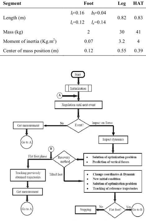
vanishes at landing time. After landing, once again the flat foot strategies are used to control the model. Figure 5 illustrates the chart flow of the approach.
The solution of optimization problem is performed using MATLAB. Event based ODE solver of MATLAB is also exploited to integrate the Equation (1).
4. SIMULATION RESULTS AND DISCUSSION
The physical parameters of the model for the simulations are listed in Table 1. To demonstrate the capability of the method, some simulation scenarios are considered.
First, consider a 15Ns forward impulsive force is applied during quiet standing at time t=1.2s. The entire recovery duration has been considered to be 2 second similar to the recovery time of real subjects [5]. The variation of vertical forces under the heel and the toe is shown in Figure 6. As seen, the value of vertical forces never cross zero and so the foot remains flat against this amount of disturbance.
TABLE 1. Anthropometric parameters of the simulated model
Segment Foot Leg HAT
Length (m) lf=0.16 hf=0.04
lc=0.12 la=0.14
0.82 0.83
Mass (kg) 2 30 41
Moment of inertia (Kg.m2) 0.07 3.2 4
Center of mass position (m) 0.12 0.55 0.39
Figure 6. The variation of vertical forces under the heel and the toe
Figure 7. Angle and Angular velocity of the joints during recovery
Figure 8. The applied torques during recovery
Figure 7 depicts the angle and angular velocity of the joints during simulation. As seen, prior to the disturbance, the variation of joints angle are zero. After the disturbance, the initial response is a flexion at the ankle and the hip joints. The flexion of the hip is more than that of the ankle, so the main strategy of the model in kinematic level is hip strategy. The straight-line segments of the trajectories of angular velocities show the instantaneous jumps after the disturbance. Figure 8 shows the applied torques on the joints. As seen, after the disturbance, the response initiates with extensor torques at the ankle and at the hip.
Figure 9. Displacement of XCoM and CoM
Figure 10. Snapshots of the response to 15 Ns impulse
The track of CoM and XCoM (see Figure 9) indicates
a jumps of XCoM after impulsive disturbance that is
consequence of instantaneous jumps of the velocities. Figure 9 shows that CoM and XCoM remain within the
stable region during recovery. This is accomplished by tracking of the optimal trajectories. Figure 10 demonstrates the general pattern of recovery as snap shots.
The results clearly show that the biped can maintain the balance after a compensatory movements obtained by the optimization. For the above scenario, the optimum values of the design parameters were p2=5.41
and p2=-0.38.
Now, consider a relatively stronger disturbance (17.6 Ns) being applied during quiet standing at time t=1.2s. The variation of vertical forces is shown in Figure 11. As seen, the vertical force under the heel crosses zero at t=1.36s. So, the recovery includes a toe phase. Figure 12 shows the trajectory of angles and angular velocities. The initial response is a flexion at the ankle and the hip joint. The foot tilts around the toe and then lands and remains approximately flat. In this case, the switching between the models occurs and after landing of the foot, once again the model tries to recapture upright balance using ankle and hip torques.
0 500 1000 1500 2000 2500 3000 3500 -20
0 20
H
ip
(
de
g)
0 500 1000 1500 2000 2500 3000 3500 -50
0 50
H
ip
(d
eg
/s)
0 500 1000 1500 2000 2500 3000 3500 -1
0 1
A
nk
le
(deg
/s)
0 500 1000 1500 2000 2500 3000 3500 158
160 162
Time(ms)
F
o
ot
(d
eg)
0 500 1000 1500 2000 2500 3000 3500 -1
0 1
Time(ms)
F
oo
t(
de
g/
s)
0 500 1000 1500 2000 2500 3000 3500 -70
-69 -68
A
nk
le
(
de
g)
0 500 1000 1500 2000 2500 3000 3500
-20 0 20
Time(ms) uHip
(
N
m)
0 500 1000 1500 2000 2500 3000 3500
-50 0 50
Time(ms) uAn
kle
(
N
m)
-0.50 0 0.5 0.5
1 1.5
t = 1000 (ms)
-0.50 0 0.5 0.5
1 1.5
t = 1250 (ms)
-0.50 0 0.5 0.5
1 1.5
t = 1500 (ms)
-0.50 0 0.5 0.5
1 1.5
t = 1750 (ms)
-0.50 0 0.5 0.5
1 1.5
t = 2000 (ms)
-0.50 0 0.5 0.5
1 1.5
t = 2250 (ms)
-0.50 0 0.5 0.5
1 1.5
t = 2500 (ms)
-0.50 0 0.5 0.5
1 1.5
t = 2750 (ms)
-0.50 0 0.5 0.5
1 1.5
Figure 13 demonstrates the applied torques on the joints during recovery. As seen, after the disturbance, the response initiates with an extensor torque at the ankle and extensor torque at the hip. When the ankle torque reaches to the upper bound, it remains unchanged until the foot lands. Comparison of Figures 13 and 8 show the higher value of torques for the recovery in the toe phase. This is reasonable, because in this phase the model was considered to be an under-actuated model. From Figure 13 it is also clear that the model decrease the hip torque, during the toe phase, to come back to the flat phase posture. The track of CoM and XCoM of the
model is shown in Figure 14. It is seen that XCoM
approaches to the border of the base of support and then comes back to the safe area. It is worth noting that the torque exerted by the toe has been considered to be zero. We believe that by consideration of the toe actuation, the fluctuation of XCoM will be decreased.
This can be viewed as an extra safety factor of the method of this study. Figure 15 shows snapshots of the compensatory pattern during simulation. For the above scenario, the optimum values of the design parameters for foot tilted phase were p1=-1.95 and p2=121.42.
In the rest of this section, the simulated results are compared with human reactions against disturbances. Unfortunately, there is little experimental data for human balance recovery against impulsive disturbances with consideration of foot tilting.
Figure 11. The variation of vertical forces under the feet
Figure 12. Angles and angular velocities of the joints during recovery
Figure 13. The applied torques on the actuated joints
Figure 14.Displacement of XCoM and CoM .
Figure 15. Snapshots of the response to 17.6 NS impulse
In the present paper, comparison is done using the data from Wilson et al. [5], in which the participants in the experiment have not been limited to keep their foot flat after disturbance. An Anteriorly-directed force perturbations have been applied to the upper back of subjects to challenge their postural control system without eliciting a stepping response. Postural strategy has been quantified using joint angles and joint torques
0 500 1000 1500 2000 2500 3000 3500 4000 4500 -20
-10 0
H
ip
(deg)
0 500 1000 1500 2000 2500 3000 3500 4000 4500 -100
-50 0 50
H
ip
(de
g/
s)
0 500 1000 1500 2000 2500 3000 3500 4000 4500 -71
-70 -69 -68
A
n
kl
e
(de
g)
0 500 1000 1500 2000 2500 3000 3500 4000 4500 -5
0 5
An
kl
e(
deg
/s)
0 500 1000 1500 2000 2500 3000 3500 4000 4500 154
156 158 160
Time (ms)
Fo
ot
(deg)
0 500 1000 1500 2000 2500 3000 3500 4000 4500 -10
0 10
Time (ms)
Fo
ot
(deg
/s)
0 500 1000 1500 2000 2500 3000 3500 4000 4500 -50
0 50 100
Time(ms)
uHip
(N
m)
0 500 1000 1500 2000 2500 3000 3500 4000 4500 -100
0 100
Time(ms)
uAnk
le
(N
m)
-0.50 0 0.5 0.5
1 1.5
t=1000(ms)
-0.50 0 0.5 0.5
1 1.5
t=1250(ms)
-0.50 0 0.5 0.5
1 1.5
t=1500(ms)
-0.50 0 0.5 0.5
1 1.5
t=1750(ms)
-0.50 0 0.5 0.5
1 1.5
time : 2000(ms)
-0.50 0 0.5 0.5
1 1.5
t=2250(ms)
-0.50 0 0.5 0.5
1 1.5
t=2500(ms)
-0.50 0 0.5 0.5
1 1.5
t=2750(ms)
-0.50 0 0.5 0.5
1 1.5
t=3000(ms)
-0.50 0 0.5 0.5
1 1.5
t=3250(ms)
-0.5 0 0.5 0
0.5 1 1.5
Y
(
m)
t=3500(ms)
-0.5 0 0.5 0
0.5 1 1.5
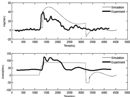
for the ankle, knee, hip, and low back joints. We have tried to do the simulations with the same anthropometric parameters, amplitude of disturbance, recovery time and etc. The results are compared only for the ankle and the hip joints of the normal subjects (un-fatigued subjects, see Wilson et al. [5]). Figure 16 shows the comparison of the normalized simulated ankle and hip angles with the corresponding experimental data. A partly promising closeness is seen for the trend of trajectories. Experimental results show the larger variation of the ankle joint. The main discrepancy between the results for the ankle is at the beginning of the disturbance. Figure 17 shows the comparison of the ankle and hip torques. As seen, the amount of ankle torque for real subjects is not zero before the beginning of the disturbance. At the end of recovery phase, when the foot lands, simulation results show the pattern in contrast with the experimental results. Generally, there are a lot of sources of disparity between the results. Some of them are:
a) The simulation model is simple. It should be mentioned that by increasing the dimension, the modeling complexity grows by an exponentially fast rate and this leads to a computationally expensive calculations especially for optimization problem. b) Human postural reactions can be affected by
neurological (e.g. muscular activation delay), psychological (e.g. fear of falling) and mechanical limitations (maximum torque and joint ranges of motion). For the simulated model, only the mechanical limitations make sense.
c) Anticipatory postural adjustments (APAs) are seen in human postural muscles prior to onset of perturbations.
d) Simulated model did not include the time delays that are inherent in Central Nervous System (CNS) feedback control.
e) Compliancy is seen in the human postural responses to external disturbances, but it has not been considered in the current study.
Figure 16. Comparison of the normalized simulated hip and ankle angular trajectories with corresponding experimental data
Figure 17. Comparison of the simulated hip and ankle torques with corresponding experimental data
5. CONCLUSIONS
A framework for control of the upright balance has been presented that includes both flat and tilted foot phases in response to the unexpected impulsive disturbances. In this framework, after a disturbance, tilting of the foot is predicted by evaluation of the Vertical Forces criterion. If the prediction shows the foot tilting, then proper trajectories are obtained for the upper segments in a way that return the foot to the flat phase. Optimization is formulated based on the receding horizon approach. Extrapolated Center of Mass criteria has been used as the stability constraint in the optimization procedure. The results showed that by using this approach, the biped model is able to reject disturbance and maintain the dynamic balance in the toe phase (similar to human). We have tried to verify the simulations by relying on the available experimental data from literature. In spite of disparity between the simulations and experiments, we believe the obtained results are promising. By adding some modeling features, the ability of the method can be enhanced to obtain more natural and human like patterns of recovery. In a future work, the control method will be extended to a model with higher degrees of freedom. Time delay and compliancy in responses have not been considered in the current study. We plan to add these features in the modeling to obtain results which are mostly close to the experiments. The quality of recovery (energy consumption), and using of other stability constraints in the optimization could also be considered.
6. REFERENCES
1. Horak, F. B., "Postural orientation and equilibrium: What do we need to know about neural control of balance to prevent falls?",
2. Alexandrov, A. V., Frolov, A. A., Horak, F., Carlson-Kuhta, P. and Park, S., "Feedback equilibrium control during human standing", Biological Cybernetics, Vol. 93, No. 5, (2005), 309-322.
3. Creath, R., Kiemel, T., Horak, F., Peterka, R. and Jeka, J., "A unified view of quiet and perturbed stance: Simultaneous co-existing excitable modes", Neuroscience letters, Vol. 377, No. 2, (2005), 75-80.
4. Qu, X., Nussbaum, M. A. and Madigan, M. L., "A balance control model of quiet upright stance based on an optimal control strategy", Journal of Biomechanics, Vol. 40, No. 16, (2007), 3590-3597.
5. Wilson, E. L., Madigan, M. L., Davidson, B. S. and Nussbaum, M. A., "Postural strategy changes with fatigue of the lumbar extensor muscles", Gait & Posture, Vol. 23, No. 3, (2006), 348-354.
6. Aftab, Z., Robert, T. and Wieber, P.-B., "Predicting multiple step placements for human balance recovery tasks", Journal of Biomechanics, (2012).
7. Sun, Y. and Wu, C. Q., "Stability analysis via the concept of lyapunov exponents: A case study in optimal controlled biped standing", International Journal of Control, Vol. 85, No. 12, (2012), 1952-1966.
8. Ghorbani, R., Wu, Q. and Wang, G. G., "Nearly optimal neural network stabilization of bipedal standing using genetic algorithm", Engineering Applications of Artificial Intelligence, Vol. 20, No. 4, (2007), 473-480.
9. Gorce, P., "Dynamic postural control method for biped in unknown environment", Systems, Man and Cybernetics, Part A: Systems and Humans, IEEE Transactions on, Vol. 29, No. 6, (1999), 616-626.
10. Abdallah, M. and Goswami, A., "A biomechanically motivated two-phase strategy for biped upright balance control", in Robotics and Automation, 2005. ICRA 2005. Proceedings of the IEEE International Conference on, IEEE, (2005), 1996-2001. 11. Nenchev, D. N. and Nishio, A., "Ankle and hip strategies for
balance recovery of a biped subjected to an impact", Robotica, Vol. 26, No. 05, (2008), 643-653.
12. Liu, C. and Atkeson, C. G., "Standing balance control using a trajectory library", in Intelligent Robots and Systems, IROS 2009. IEEE/RSJ International Conference on, IEEE, (2009), 3031-3036.
13. Tahboub, K. A., "Biologically-inspired humanoid postural control", Journal of Physiology-Paris, Vol. 103, No. 3, (2009), 195-210.
14. Lee, S., Kim, M., Kim, J. and Choi, M.-T., "Receding horizon viability radius for stability of humanoid robot under external
perturbation", Journal of Mechanical Science and Technology, Vol. 24, No. 5, (2010), 1127-1139.
15. Kanamiya, Y., Ota, S. and Sato, D., "Ankle and hip balance control strategies with transitions", in Robotics and Automation (ICRA), 2010 IEEE International Conference on, IEEE., (2010), 3446-3451.
16. Stephens, B., "Push recovery control for force-controlled humanoid robots", Carnegie Mellon University, (2011) 17. Vukobratovic, M., Milojevic, M., Tzafestas, S., Jovanovic, M.
and Potkonjak, V., "Human-and-humanoid postures under external disturbances: Modeling, simulation, and robustness. Part 2: Simulation and robustness", Journal of Intelligent & Robotic Systems, Vol. 63, No. 2, (2011), 211-231.
18. Naderi, D., Sadeghi-Mehr, M. and Fard, B. M., "Optimization-based dynamic prediction of human postural response under tilting of base of support", International Journal of Humanoid Robotics, Vol. 9, No. 02, (2012).
19. Naderi, D., Miripour Fard, B. and Sadeghi-Mehr, M., "Optimal prediction of human postural response under anterior-posterior platform tilting", Communications in Nonlinear Science and Numerical Simulation, (2012).
20. Kouchaki, E., Wu, C. Q. and Sadigh, M. J., "Effects of constraints on standing balance control of a biped with toe-joints", International Journal of Humanoid Robotics, Vol. 9, No. 03, (2012).
21. Humphrey, L. and Hemami, H., "A computational human model for exploring the role of the feet in balance", Journal of Biomechanics, Vol. 43, No. 16, (2010), 3199-3206.
22. Sobotka, M., "Hybrid dynamical system methods for legged robot locomotion with variable ground contact", PhD thesis, Technische Universität München, (2007)
23. Winter, D. A., "Biomechanics and motor control of human movement", Wiley. com, (2009).
24. Buss, M., Glocker, M., Hardt, M., Von Stryk, O., Bulirsch, R., and Schmidt, G., "Nonlinear hybrid dynamical systems: Modeling, optimal control, and applications, in Modelling, analysis, and design of hybrid systems", Springer, (2002), 311-335.
25. Fard, B. M., Bagheri, A. and Nariman-Zadeh, N., "Limit cycle walker push recovery based on a receding horizon control scheme", Proceedings of the Institution of Mechanical Engineers, Part I: Journal of Systems and Control Engineering, Vol. 226, No. 7, (2012), 914-926.
Receding Horizon Based Control of Disturbed Upright Balance with
Consideration of Foot Tilting
RESEARCH NOTE
B. Miripour Farda, A. Bagheri b, A. S. Khoskbijarib
a Department of Robotics Engineering, Hamedan University of Technology, Hamedan, Iran.
b Department of Mechanical Engineering, the University of Guilan, Rasht, Iran
P A P E R I N F O
Paper history:
Received 08 February 2013
Received in revised form 24 March 2013 Accepted 18 April 2013
Keywords:
Hybrid Model
Receding Horizon Approach Upright Balance
External Disturbances
هﺪﯿﮑﭼ
ﺖﯿﻌﻗﻮﻣﯽﺧﺮﺑرد
،دﻮﺷدراوهدﺎﺘﺴﯾاﺖﻟﺎﺣردنﺎﺴﻧاﺮﺑﯽﺟرﺎﺧشﺎﺸﺘﻏاﮏﯾﺮﮔا،ﺎﻫ
ﺺﺨﺷ ﯽﻣ
ﻪﺠﻨﭘيورﺮﺑﻦﺘﻓرﺎﺑﺪﻧاﻮﺗ
)
ﺎﭘ
ﻪﻨﺷﺎﭘ
(
مﺎﮔﻪﺑزﺎﯿﻧنوﺪﺑو
ﯿﻧوﺪﻨﮐﻆﻔﺣاردﻮﺧﯽﮑﯿﻣﺎﻨﯾدلدﺎﻌﺗ،يرادﺮﺑ
ﺪﺘﻔ
.
نﻮﻨﮐﺎﺗ حﺮﻃ
رﺎﯿﺴﺑﯽﻟﺮﺘﻨﮐيﺎﻫ
لﺮﺘﻨﮐياﺮﺑيدﺎﯾز
مﺎﮔنوﺪﺑ،ﯽﺟرﺎﺧشﺎﺸﺘﻏاﺮﺑاﺮﺑردندﺎﺘﺴﯾا
ﺖﺳاهﺪﺷدﺎﻬﻨﺸﯿﭘيرادﺮﺑ
.
ﺮﻃﺮﺘﺸﯿﺑرد
ح
ﺶﻫوﮋﭘ،هﺪﺷدﺎﻬﻨﺸﯿﭘيﺎﻫ
ﺖﻬﺟناﺮﮔ
هدﺎﺳ
هدﺮﮐضﺮﻓ،ﻪﻟﺎﺴﻣيزﺎﺳ
ﯽﻣﯽﻘﻓاهراﻮﻤﻫﺎﭘﻒﮐ،لدﺎﻌﺗﯽﺑﺎﯾزﺎﺑمﺎﮕﻨﻫردﻪﮐﺪﻧا
ﺪﻧﺎﻣ
.
ﯽﻣﻪﯾاراﯽﺑﻮﭼرﺎﭼﻪﻟﺎﻘﻣﻦﯾارد
دﻮﺷ
ارودﻞﻣﺎﺷﻪﮐ
ﯽﻣﻢﻫﺎﭘن
دﻮﺷ
.
لﺪﻣﻖﯾﺮﻃزارﺎﮐﻦﯾا
ﻫيزﺎﺳ
ﺪﯾﺮﺒﯿ ي
زاهدﺎﻔﺘﺳاو
حﺮﻃ
ﻖﻓاﺎﺑلﺮﺘﻨﮐشورسﺎﺳاﺮﺑﯽﻟﺮﺘﻨﮐ
ﺲﭘ
ﺖﺳاهﺪﺷمﺎﺠﻧاور
.
ﻢﯿﻤﺼﺗ
ﻪﯿﮑﺗيدﻮﻤﻋيوﺮﯿﻧرﺎﯿﻌﻣﯽﺑﺎﯾزراسﺎﺳاﺮﺑلدﺎﻌﺗﯽﺑﺎﯾزﺎﺑيﻮﮕﻟابﺎﺨﺘﻧاياﺮﺑيﺮﯿﮔ
هﺎﮔ
ردﺎﻫ
ﺶﯿﭘﻖﻓاﮏﯾ
ﯽﻣمﺎﺠﻧاﯽﻨﯿﺑ
دﻮﺷ
.
ﺶﯿﭘﺮﮔا
ﯽﻨﯿﺑ ﻫ
يﺎﻀﻋاياﺮﺑﯽﺒﺳﺎﻨﻣﯽﺘﮐﺮﺣيﻮﮕﻟا،ﺪﺷﺎﺑشﺎﺸﺘﻏاﺮﺛاردﺎﭘنارودزاﯽﮐﺎﺣﺎ
تﺎﺑرﯽﯾﻻﺎﺑ
)
ﺎﻀﻋا ي
ﻞﻤﻋياراد
ﺮﮔ
(
ﯽﻣﺖﺳدﻪﺑ
ﺎﭘﻒﮐﺎﺗﺪﯾآ
)
ﻞﻤﻋنوﺪﺑﻮﻀﻋ
ﺮﮔ
(
ﺪﻧادﺮﮔﺮﺑﯽﻘﻓاﺖﻟﺎﺣﻪﺑار
.
يﺎﻫﻮﮕﻟا
هﺪﻨﻨﮐلﺮﺘﻨﮐﮏﯾﻂﺳﻮﺗهﺪﻣآﺖﺳدﻪﺑﯽﺘﮐﺮﺣ
ي ﺲﭘ رﻮﺧ
ﯽﻣاﺮﺟا
ﺪﻧﻮﺷ
.
ﺎﺑلﺮﺘﻨﮐشوررد
ﺲﭘﻖﻓا
نوﺮﺑرادﺮﺑرﺎﯿﻌﻣ،ور
ﯽﺑﺎﯾ
ﺖﺳاهﺪﺷهدﺎﻔﺘﺳايراﺪﯾﺎﭘﺪﯿﻗناﻮﻨﻋﻪﺑمﺮﺟﺰﮐﺮﻣهﺪﺷ
.
ﺞﯾﺎﺘﻧ
هﺪﻨﻫدنﺎﺸﻧ،
ي
ردنﺎﺴﻧاﻪﺑﺎﺸﻣﯽﺗﺎﮐﺮﺣﺪﯿﻟﻮﺗردشورﺖﯿﻘﻓﻮﻣ
ﻪﺑﺮﺿشﺎﺸﺘﻏاﺮﺑاﺮﺑ
ﯿﺟرﺎﺧيا
ﺖﺴ
.
ﺎﺘﻧ ﺞﯾ ﻪﯿﺒﺷ
ﺎﺑيزﺎﺳ
ﺞﯾﺎﺘﻧ
ﺖﺳاهﺪﺷﻪﺴﯾﺎﻘﻣﮏﯿﻧﺎﮑﻣﻮﯿﺑﻊﺑﺎﻨﻣرددﻮﺟﻮﻣﯽﺑﺮﺠﺗ
.