Simulation of Analog Modulation and Demodulation
Techniques in Virtual Instrumentation and Remote Lab
https://doi.org/10.3991/ijoe.v13i10.7575
Nehru Kandasamy!!", Nagarjuna Telagam, V.R Seshagiri Rao
Institute of Aeronautical Engineering, Hyderabad, India. [email protected]
T.S.Arulananth
MLR Institute of Technology, Hyderabad, India.
Abstract—An analog method to modulate and demodulate signals is presented in this short paper. This paper discusses modulation techniques with the LabVIEW-based RF communications package, developed for the illustration of different modulation types in undergraduate virtual instrumentation labs. The tool can generate and display the time and frequency domain behaviours of modulated signals with the help of spectral and tone measurements icon. All the modulation parameters can be specified by the user. This signal processing tool in the block diagram is also enables adding noise to a modulated signal, and selecting among different types of baseband pulse-shaping filters. The transition between the virtual and the real world is accomplished via data-acquisition cards, installed in PCs. The results of simulation show that the interface of each system is beautiful, the parameters are easy to adjust and the process of modulation-demodulation is simpler than the traditional system which is designed by hardware circuit. This Amplitude modulation is tested in NI USRP RIO 2920 as transmitter. The carrier frequen-cy used is 555-1650 KHz for amplitude modulation and the carrier frequenfrequen-cy is 88-108 MHz in India.
Keywords—NI USRP RIO 2920, amplitude and frequency modulation, Signal processing
1
Introduction
Lab-VIEW is a development environment for problem solving, accelerated productivity and continual innovation. Hardware integration can be done rapidly which aids to acquire and visualize data sets from virtual I/O devices and real time signals. It is combined with graphical programming syntax that reduces programming time [5]. LabVIEW programs are called Virtual Instruments or VIs, because their appearance and operation imitate physical instruments such as oscilloscopes, multimeters, signal generators and other basic electronic input/output devices [6]. Graphical user interface system is explained for analog data.[7].
2
Implementation
With the help of available tool box named signal processing in block diagram the simulation signal icon. The user can specify the parameters such as amplitude, fre-quency and phase. The user can also add the noise to the signal.
2.1 Simulation of Amplitude modulation and demodulation
( )
c(1
a mcos2
m)cos2
cs t
=
A
+
K A
!
f t
!
f t
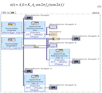
(1)Fig 1 explains the operation of amplitude modulation in which the amplitude of carrier signal is varied in accordance with message signal amplitude variations. The spectral measurements give the frequency domain representation in linear value.
Fig. 2. Front Panel output of amplitude modulation
Fig 2 shows the ouput. With the help of graph palette the waveforms can be ana-lyzsed in time and frequency domain clearly. The user can verify different modulation schemes such as under modulation, critical modulation and over modulation.
2.2 Square law modulator
The standard equation of the square law device with modulator is given as
2
0 1
( )
( ( )
( ))
( ( )
( ))
s t
=
a m t c t
+
+
a m t c t
+
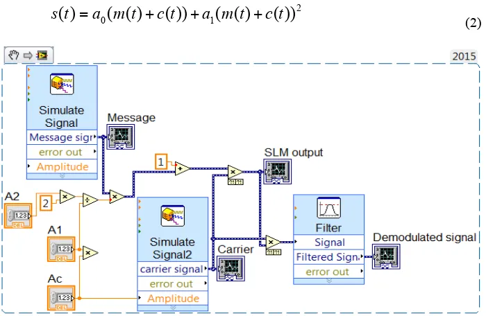
(2)Fig 3 gives the implementation of amplitude modulation using square law device. The parameters
a
0 anda
1 will decide the AM output because amplitude sensitivity1 0
2 /
a
k
=
a a
(3)Fig. 4. Front panel output of square law modulator
Fig 4 shows the ouput of modulator and demodulation. The demodulation of the signal is done with respect to filter with butterworth type of order 5, and used as low pass filter with user specified cut off frequency.
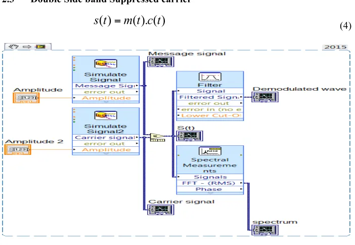
2.3 Double Side band Suppressed carrier
( )
( ). ( )
s t
=
m t c t
(4)Fig 5 shows the implementation of balanced modulator. The modulation parame-ters are specified by the user. It is nothing but product of carrier signal with message signal and the spectral measurements icon gives the frequency domain representation. m(t) is the modulating signal and c(t) is carrier signal.
Fig. 6. Front panel output of balanced modulator
Fig 6 shows the front panel output. It shows three waveform graphs. The balanced modulator output gives the perfect modulation index i.e the ratio of amplitude of message signal with amplitude of carrier signal.
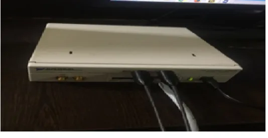
Fig. 7. NI USRP RIO 2920
Fig. 8. VI Snippet of Amplitude and Frequency modulation using ni USRP Configuration
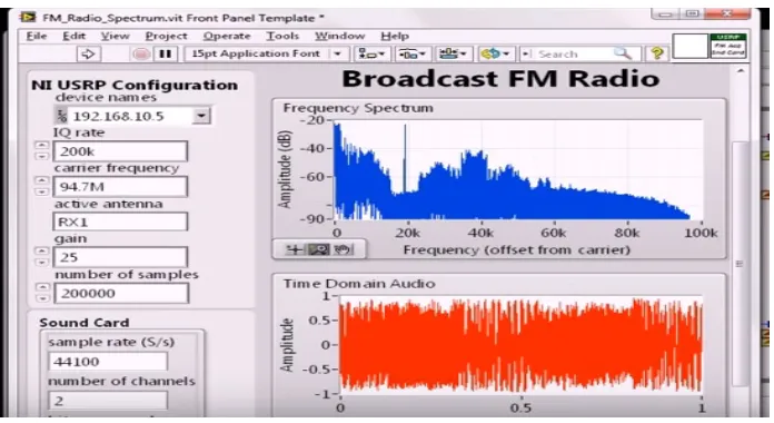
USRP is wide band MHz receiver and centered around 93.5 MHz. Each peak in the output is local FM station. By zooming in with graph palette we can see different FM stations occupying a bandwidth of 200KHZ. The IQ Sampling rate can be changed according to user. The input is taken from sound card. The demodulation is done by using phase wrapping icon. The final operation resample’s the original signal with 50K samples. The frequency spectrum can also be plotted by the user specification. By tuning the frequency at the receiver the user can able to listen sound file directly.
Fig. 9. USRP RIO Simulation results
3
Conclusion
In this short paper the implementation of AM and FM modulation techniques are successfully carried out using NI USRP RIO 2920 and LabVIEW. By observing the results obtained we can conclude that demodulation of the modulated signal can be achieved successfully using Software defined radio receiver which is tuned to operat-ing frequency. The amplitude modulation receiver is designed with the carrier fre-quency of 1560 KHz and same design is implemented for FM receiver with carrier frequency of 94 MHZ.
4
References
[1]Lucky, R.W. Sal, J. Weldon (1968), Principles of Data Communication. McGraw-Hill, New York.
[2]Schwartz, M. (1990), Information Transmission, Modulation and Noise, McGraw-Hill, New York.
[3]K.Sharma, A.Mishra, Rajiv Saxena (2010). Analog & Digital Modulation Techniques: An overview. International Journal of Computing Science and Communication Technologies. July Vol.3, No.1.
[4]C. Uluisik, L. Sevgi. (2012). A LabVIEW-Based Analog Modulation Tool for Virtual and Real Experimentation, IEEE Antenna and Propagation Magazine, December Vol 54, No 6. [5]Korrapati, Raghu B, Swain, Nikunja K. (2000). Study of Modulation Using Virtual
In-struments. Allied Academies International Conference. Academy of Information and Man-agement Sciences.Proceedings;Arden, vol 4.1, pp-78-83.
[6]Ji Shujiao, Zhu Ming, Lei Yanmin (2013). The Simulation Design of Communication Sys-tem Based on Lab VIEW. 2nd International Conference on Measurement, Information and Control.
[7]Telagam, N., Kandasamy, N., & Nanjundan, M. (2017). Smart Sensor Network Based High Quality Air Pollution Monitoring System Using Labview. International Journal of Online Engineering (iJOE), 13(08), 79-87.https://doi.org/10.3991/ijoe.v13i08.7161
5
Authors
Nehru Kandasamy (Corresponding Author) received his Bachelor Degree in Erode Sengunthar Engineering College, Anna University in 2005. And he obtained his Master Degree in R.M.K Engineering, Anna University in 2007.And he also ob-tained outstanding master student at that year. He is obob-tained his Ph.D in 2014 at Faculty of Information and Communication Engineering, Anna University, India. His main research interest is in the area of Low Power VLSI, Testing of VLSI Circuits, FPGA Design, CAD for VLSI, Signal processing. He published 25 papers in Scopus Indexed journals. ([email protected]).
is working as Assistant Professor. He received his Bachelor degree from JNTU Uni-versity/ Narayana Engineering College in 2011. He received his Master degree from Anna University/ Loyola Institute of Technology in 2013. He is Anna University rank holder (20) for M.E degree in 2013.He has nearly 4 years of experience in teaching and research. He published 15 papers in Scopus Indexed Journals. He is Certified LabVIEW Associate Developer. ([email protected]).
Prof. V R Seshagiri Rao works as head of department inElectronics and Commu-nication Engineering, Institute of Aeronautical Engineering, Hyderabad, India. Cur-rently he is pursing Ph.D in JNTU Hyderabad. His area of specialization is Fault Tol-erance Systems. He has 31 years of experience in teaching and research. ([email protected])
Dr. T.S.Arulananth is with department of Electronics and communication Engi-neering, MLR institute of technology, Hyderabad, India. His areas of specialization is image processing, Embedded systems and Communication systems. He published 30 papers in Scopus indexed journals. He also published two books for undergraduate students in Anna university Chennai. ([email protected]).