Available Online At www.ijpret.com
INTERNATIONAL JOURNAL OF PURE AND
APPLIED RESEARCH IN ENGINEERING AND
MODELING AND FLOW ANALYSIS OF MODERN FIGHTER AIRCRAFT
CONFIGURATION USING
1. Assistant Professor, Department of Aeronautical Engineering, MVJCE, Bangalore. 2. Assistant Professor, Department of Aeronautical Engineering, MVJCE, Bangalore.
3. UG student, Project Assistant, Department of Aeronautical Engineering, MVJCE,
Bangalore
.
Accepted Date:
03/03/2013
Publish Date:
01/04/2013
Keywords
Canard,
Downwash Effects,
CFD
Corresponding Author
Mr. Nishanth. P
IJPRET-QR CODE
Available Online At www.ijpret.com
INTERNATIONAL JOURNAL OF PURE AND
APPLIED RESEARCH IN ENGINEERING AND
TECHNOLOGY
A PATH FOR HORIZING YOUR INNOVATIVE WORKMODELING AND FLOW ANALYSIS OF MODERN FIGHTER AIRCRAFT
CONFIGURATION USING -CFD
NISHANTH.P1, N.RAJAMURUGU2, ABILDEV.P3
Department of Aeronautical Engineering, MVJCE, Bangalore. Department of Aeronautical Engineering, MVJCE, Bangalore.
student, Project Assistant, Department of Aeronautical Engineering, MVJCE,
Abstract
The use of canard in advanced aircraft for control and improved aerodynamic performance is a t
interest and research. The canard is a control device, which is placed in front of main wing adding to increase in maximum lift and decrease in drag. The presence of canard in close proximity to the wing results in a highly coupled canard aerodynamic flow field which can include downwash/upwash
effects, vortex-vortex interactions and vortex
interactions. Emphasis is placed on the effects of canard on aerodynamic performance and further comparison is made with and without canard configuration.
INTERNATIONAL JOURNAL OF PURE AND
APPLIED RESEARCH IN ENGINEERING AND
A PATH FOR HORIZING YOUR INNOVATIVE WORK
MODELING AND FLOW ANALYSIS OF MODERN FIGHTER AIRCRAFT
Department of Aeronautical Engineering, MVJCE, Bangalore. Department of Aeronautical Engineering, MVJCE, Bangalore.
student, Project Assistant, Department of Aeronautical Engineering, MVJCE,
The use of canard in advanced aircraft for control and improved aerodynamic performance is a topic of continued interest and research. The canard is a control device, which is placed in front of main wing adding to increase in maximum lift and decrease in drag. The presence of canard in close proximity to the wing results in a highly coupled canard-wing aerodynamic flow field which can include downwash/upwash
vortex interactions and vortex-surface
interactions. Emphasis is placed on the effects of canard on aerodynamic performance and further comparison is made
Available Online At www.ijpret.com
1. INTRODUCTION
A primary purpose of fighter aircraft is to
destroy other aircraft, either in offensive or
defensive modes of operation, or to pose
such a compelling threat that enemy air
operations are effectively curtailed. Enemy
fighters, bombers, patrol and
reconnaissance aircraft, as well as
ground-support and transport aircraft, are the prey
of the fighter. To perform its intended
function, the fighter must be able to reach a
favorable position for inflicting crippling
damage on the enemy. This means that the
fighter pilot must first be able to detect the
enemy aircraft; the methods of detection
employed in the First World War were
primarily visual. Thus, the aircraft and
pilot's position in it must be designed to
provide the widest possible field of view.
Detection means little, however, unless the
aircraft possesses the performance and
maneuverability necessary to achieve a
favorable attack position and provides a
steady gun platform together with
sufficiently powerful armament to destroy
the enemy once a favorable position has
been achieved. Some of the performance
and maneuverability characteristics of
importance are speed in various flight
conditions, rate of climb and ceiling, roll
rate, turning radius and climb capability
while in a turn, and range and endurance.
The “tailless delta-canard” configuration
has the horizontal control surfaces moved
forward to become a canard in front of the
wing. When the aircraft pitches up, instead
of forcing the tail down decreasing overall
lift, the canard lifts the nose, increasing the
overall lift. Because the canard is picking up
the fresh air stream instead of the wake
behind the main wing, the aircraft can
achieve better control authority with a
smaller-size control surface, thus resulting
in less drag and less weight.
Canard Aircraft Characteristics
Canard foreplanes act in a similar way to
conventional tailplane and elevators, but
due to swap in position about the centre of
gravity control surface actions have the
opposite effect.
A canard arrangement produces more lift
than a conventional set-up when total lift
produced is considered. During manoeuvres
Available Online At www.ijpret.com
the main wing, adding to the lift to climb
and decreasing the lift to descend. This
means that the aircraft can move tighter
and faster than with a conventional set-up.
The wing root operates in the downwash
from the canard surface, which reduces its
efficiency, although the effect of the
downwash does not cause as large of a
problem as the tailplane would experience
in a conventional set-up.
The wing tips operate in the upwash from
the canard surface, which increases the
angle of attack on the tips and promotes
premature separation of the air flowing
over the wing tip. This premature
separation at one tip or the other would
promote wing-drop at the approach to the
stall, leading to a spin. This must be avoided
by precautions in the design of the wing,
and may require extra weight in the wing
structure outboard of the wing root.
Because the canard must be designed to
stall before the main wing, the main wing
never stalls and so never achieves its
maximum lift coefficient. This may require a
larger wing to provide extra wing area in
order for the airplane to achieve the
desired takeoff and landing distance
performance.
2. PROBLEM STATEMENT AND ANALYSIS
The major objective of the present project
is to compute the aerodynamic forces and
moment coefficient through CFD package
HYENA for a typical modern fighter canard
controlled aircraft configuration for the
following cases:
i) Canard deflection at δc = 0 deg; with
variation in angle of attack
ii)Canard deflection at δc = +10 deg; with
variation in angle of attack
iii)Canard deflection at δc = -10 deg; with
variation in angle of attack
The scope of the present work is detailed as
follows;
Geometric modelling of the typical
candidate canard controlled fighter aircraft
configuration using CATIA V5 modeling
software. Smoothening of the individual
components of the modern fighter aircraft
using CATIA V5 .Meshing of the aircraft
Available Online At www.ijpret.com
HYENA CFD code,Studying the streamline
using TECPLOT360 Studying the pressure
contour using TECPLOT360.
This analysis was carried out on the
principle of control volume method, where
the aircraft is fixed in space with the fluid
moving through it.
The analysis has been carried out for
various canard deflection angles such as
-10deg, 0deg, +10deg. For each canard
deflection angles various angle of attack
conditions have been implemented such as
2.50, 50, 7.50, 100, 12.50, and 150. The
pitching moment reference point is located
ahead of c.g. i.e. at the nose of the aircraft
Further, CFD analysis has been carried out
for the same aircraft without canard and
the results have been compared with the
aircraft having canard.
3. CFD Analysis Results
The fighter aircraft with canard is
considered as candidate geometry for the
present analysis. The analysis has been
carried out considering the principle that if
canard is present the total lift of the aircraft
will be increased. Keeping this principle
various canard deflection angles and
various angle of attack was implemented
for the aircraft configuration, similarly the
analysis was also carried for aircraft without
canard. The flow conditions are taken same
for all the configurations. The flow
conditions have been listed in table 3.1
3.2.1 CASE 1:Predicted CFD results for
canard deflection angle 0deg with
variation in Angle of Attack
CFD predictions have been carried out for
the fighter aircraft with 0deg canard
deflection angle. The streamlines pattern
and pressure coefficient contour for
different angle of attack conditions are
shown from the figure 3.2 to3.7. The
generated grid cell was 16lakhs. The
coefficient of lift, coefficient of drag and
coefficient of pitching moment are the
outputs from the HYENA analysis software.
The graphs plotted shown in the fig 3.8 to
Available Online At www.ijpret.com
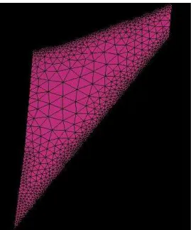
Fig 3.1 Generation of Tetrahedral mesh
for canard surface
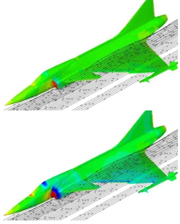
Fig 3.2 Streamline and Pressure contour
for α=2.5deg; δδδδc = 0deg, M=0.5
Fig 3.3 Streamline and Pressure contour
for α=5deg; δδδδc = 0deg, M=0.
3.2.2CASE 2 Predicted CFD results for
canard deflection angle +10deg with
variation in Angle of Attack
The canard is deflected to an angle of 10deg
and the coefficient of drag, coefficient of
lift, and coefficient of pitching moment
values has been obtained at this position of
canard. The difference between case1 and
case2 is change in the canard deflection
angle. It is clear from the graph that the
coefficient of lift increases with increase in
canard angle. The generated grid cell was
18lakhs. The streamline and pressure
Available Online At www.ijpret.com
3.11 to 3.16. The graphs are plotted shown
in the fig 3.17 to 3.19.
Fig 3.11 Generation of Tetrahedral mesh
for canard surface with 10deg deflection
Fig 3.12 Streamline and Pressure contour
for α=2.5deg; δδδδc = 10deg, M=0.5
Fig 3.13 Streamline and Pressure contour
for α=5deg; δδδδc = 10deg, M=0.5
Fig 3.14 Streamline and Pressure contour
for α=7.5deg; δδδδc = 10deg, M=0.5
Tab 8.2 Computed results of CL , CD , Cm for
δδδδc = +10deg with variation in Angle of
attack
Angle of Attack (deg)
Coefficient of Lift (CL)
Coefficient of Drag (CD)
Coefficient of Pitching Moment (CM)
2.5
8.19E-02 -1.04E-02 1.19E-01
5
1.85E-01 3.11E-03 2.89E-01
7.5
2.87E-01 2.54E-02 4.55E-01
10
3.88E-01 5.66E-02 6.22E-01
12.5
4.89E-01 9.74E-02 7.94E-01
15
Available Online At www.ijpret.com
Fig 3.18 Coefficient of lift Vs Angle Of
Attack for 10deg canard deflection angle
3.2.3CASE 3 Predicted CFD results for
canard deflection angle
-10deg with variation in Angle of Attack
The canard is deflected to an angle of
-10deg and the coefficient of drag,
coefficient of lift and coefficient of pitching
moment values has been obtained at this
position of canard. The difference between
case2 and case3 is change in the canard
deflection angle to negative. The generated
grid cell was 18lakhs. The streamline and
pressure coefficient contours are shown in
the fig 3.20 to 3.25. The graphs are plotted
shown in the fig 3.26 to 3.28.
Fig 3.21 Generation of Tetrahedral mesh
for canard surface with -10deg deflection
Fig 3.22 Streamline and Pressure contour
for α=2.5 deg; δδδδc = -10deg, M=0.5
0.00E+00 1.00E-01 2.00E-01 3.00E-01 4.00E-01 5.00E-01 6.00E-01 7.00E-01
0 2 4 6 8 10 12 14 16
Angle Of Attack(deg)
C
o
e
ff
ic
ie
n
t
o
f
li
Available Online At www.ijpret.com
Tab 8.3 Computed results of CL , CD , Cm for
δδδδc = -10deg with variation in Angle of
attack
3.2.4 CASE 4: Predicted CFD results for no
canard configuration with variation in
Angle of Attack
In the above three cases in which we
considered canard and different deflection
for canard, where as in this case CFD
prediction have been carried for the same
fighter aircraft configuration with the
absences of canard. From the above three
cases we have seen variation in the
coefficient of lift and coefficient of drag,
when subjected to different canard
deflection angles and with different angle of
attack (AOA) conditions. In the above three
cases the coefficient of lift increases with
decrease in coefficient of drag. The
streamline and pressure coefficient contour
for different angle of attack conditions are
shown in the figure 3.29 to 3.34. The
generated grid cell was 16lakhs. The graphs
are plotted shown in the fig 3.35 to 3.37.
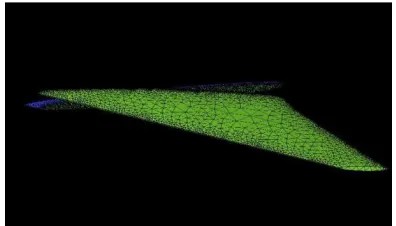
Fig 3.31 Generation of Tetrahedral mesh
for the complete aircraft without canard
configuration
Tab 8.4 Computed results of CL , CD , Cm for
No Canard configuration with variation in
Angle of attack
3.2.5CASE 5: Comparison of Predicted CFD
Results With And Without Canard
Configuration
Angle of Attack (deg)
Coefficient of Lift (CL)
Coefficient of Drag (CD)
Coefficient of Pitching Moment (CM)
2.5
6.92E-02 -8.27E-03 1.20E-01
5
1.70E-01 7.88E-03 2.85E-01
7.5
2.70E-01 3.36E-02 4.50E-01
10
3.66E-01 6.78E-02 6.14E-01
12.5
4.63E-01 1.10E-01 7.83E-01
15
5.62E-01 1.61E-01 9.60E-01
Angle of Attack (deg)
Coefficient of Lift (CL)
Coefficient of Drag (CD)
Coefficient of Pitching Moment (CM)
2.5
7.20E-02 -7.49E-03 1.22E-01
5
1.68E-01 7.29E-03 2.85E-01
7.5
2.57E-01 3.03E-02 4.40E-01
10
3.42E-01 5.97E-02 5.87E-01
12.5
4.29E-01 9.54E-02 7.45E-01
15
Available Online At www.ijpret.com
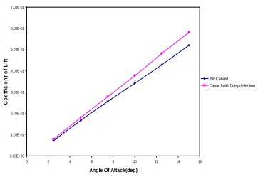
In fighter aircraft coefficient of lift is
mattered more, this case is carried out to
check the effectiveness of canard, from the
graph 3.41 to 3.46 it is evident that the
presence of canard gives more coefficient
of lift then the aircraft without canard
configuration.
From Fig 3.41 and 3.42, here the canard
deflection angle is kept at 0deg and
compared with that of no canard. From the
graph plotted the coefficient of lift
increases then that of without canard
configuration where as the coefficient of
drag remains constant with that of no
canard configuration.
From Fig 3.43 and 3.44, here the canard
deflection angle +10deg are compared with
no canard configuration. From the graph
plotted we can see increase in coefficient of
lift for canard configuration with 10deg
deflection, where as the coefficient of drag
decreases and remains constant, this
condition proves that the presences of
canard comparatively increases coefficient
of lift and decrease in coefficient of drag.
From Fig 3.45 and 3.46, here the canard
deflection angle -10deg is compared with
without canard configuration.
Fig 3.41 Comparison of CL between δδδδc =
0deg and No canard configuration
CONCLUSION
The present study shows the effect of
Canard-Wing-Body combination for a
generic modern fighter type of aircraft
configuration. A CFD simulation has been
used in the present analysis. The flow
features are obtained using CFD package
HYENA. The effect of canard control surface
is studied and was subjected to various
canard deflection angles.
Geometric modeling was carried out using
Catiav5, the details are as follows:Scaling of
the prototype aircraft prior to smoothening
0.00E+00 1.00E-01 2.00E-01 3.00E-01 4.00E-01 5.00E-01 6.00E-01 7.00E-01
0 2 4 6 8 10 12 14 16
Angle Of Attack(deg)
C
o
e
ff
ic
ie
n
t
o
f
L
if
t
Available Online At www.ijpret.com
Smoothening the individual parts of
candidate fighter aircraft.
Assembling the intake to the candidate
fighter aircraft.Deflection of the canard to
+10deg angle.Deflection of the canard to
-10deg angle. The generation of grid was
carried out using ANYSY ICEMCFD. The
computational domain and the cells of the
reference mesh were of tetrahedral type.
Finite volume analysis was carried out to
predict the aerodynamic characteristics
namely, coefficient of lift, coefficient of
drag, and coefficient of pitching moment
using HYENA and the results are presented
in tables 8.1 to 8.4 and in figures 8.8 to
8.10, 8.18 to 8.20, 8.28 to 8.30, and 8.38 to
8.46.
The flow visualization of streamline traces
for the following cases namely, .canard
control deflections of 0, -10 & 10 degrees
and for the angle of attack of 0, 2.5, 5, 7.5,
10, 12.5 and 15 degrees at a free stream
Mach number 0.5 have been computed and
were presented in figures 8.2 to 8.7, 8.12 to
8.17, 8.22 to 8.27, and 8.32 to 8.37.
It is observed from the computed CFD
results for the case of canard deflection of
100 at angle of attack of 150, the L/D ratio
improvement is about 9%.Referring to
figure 8.20 and 8.30 it is observed that for
the canard control deflection of 100 and
angle of attack of 150, pitch control
effectiveness is significantly increased.
From the above analysis, it may be evident
that the aircraft with canard configuration is
more effective than an aircraft
configuration without canard.
REFERENCES
1. Kuchemann, "Boundary Layer
Characteristics of the Miley Airfoil at Low
Reynolds Numbers," J. Aircr, vol. 21, no. 9,
pp. 658-664, September 1984.
2. Grosche, "The Application of
Computational Fluid Dynamics to Aircraft
Design," AIAA paper 86-2651, 1986.
3. Loeve, "Numerical Solutions of the Euler
Equations by Finite Volume Methods Using
Runge-Kutta Time Stepping Schemes," AIAA
paper 81-1259, 1981.
4. Lock , “Numerical Computation of
Available Online At www.ijpret.com
Fundamentals of Numerical Discretization,
Wiley, New York, 1988
5. Carmichael, "Computational
Aerodynamics Development and Outlook,"
AIAA J., vol. 17, no. 12, pp. 1293-1313,
December 1979.
6. Gregoriou, "Numerical Investigation of
the Laminar, Supersonic Flow over a
Rearward- Facing Step Using an Adaptive
Grid Scheme" M.S. thesis, Department of
Aerospace Engineering, University of
Maryland, College Park, 1982.
7. Shrout, “Applied Computational
Aerodynamics, Progress in Astro-
Astronautics and Aeronautics Series”, vol.
125, AIAA, Washington, D.C., chap. 4, pp.
91-130, 1990.
8. Liu, Da-Ming, Computational
Techniques for Fluid Dynamics, vol. II:
Specific Techniques for Different Flow
Categories, Springer-Verlag, Berlin, 1988.
9. Ottensoser,Jonah, Computational Fluid
Dynamics for Engineers, Engineering
Education System, Austin, Tex., 1989.
10.Paulson, J. W., Jr.; Thomas, J. L,
Transitions and interactions of
inviscid/viscous,
compressible/incompressible, and
laminar/turbulent flows. Int. J. Num.
Meth.Fl,31,223^6.
11.Paulson, J. W., Jr.; Thomas, J. L.;
Winston, M. M, "Adaptive Solutions for
Compressible Flows on Unstructured,
Strongly Anisotropic Grids," in C. Hirsch, J.
Periaux, and W. Kordulla (eds.),
Computational Fluid Dynamics '92, vol. 2,
Elsevier, Amsterdam, 1992, pp. 945-951.
12.Thomas, J. L.; Paulson, J. W., Jr.; Yip, L.
P, "Comparative Study of Inviscid and
Viscous Flows Over an STS," Computational
Fluid Dynamics '92, vol. 1, Elsevier,
Amsterdam, 1992, pp. 323-330.
13.Joseph P. Landfield* and Dario
Rajkovict, "Multigrid for Hypersonic Viscous
Two- and Three-Dimensional Flows," AIAA
paper 91-1572-CP, Proc. AIAA 10thComput.
Fluid Dyn. Conf, 1991.
14.ICEM-CFD Tutorial Manual: Meshing
Modules Version 11, ANSYS, Inc.
Available Online At www.ijpret.com