ISAR Image Improvement Using STFT Kernel Width
Optimization Based On Minimum Entropy Criterion
M. Modarres-Hashemi i, M. Dorostgan ii and M. M. Naghshiii *
i M. Modarres-Hashemi is with the ECE Department of Isfahan University of Technology, Isfahan, Iran (email: [email protected]) ii M. Dorostgan is with the ECE Department of Isfahan University of Technology, Isfahan, Iran ( email:[email protected])
iii* Corresponding Author, M. M. Naghsh is with the ECE Department of Isfahan University of Technology, Isfahan, Iran (email: [email protected])
ABSTRACT
Nowadays, Radar systems have many applications and radar imaging is one of the most important of these applications. Inverse Synthetic Aperture Radar (ISAR) is used to form an image from moving targets. Conventional methods use Fourier transform to retrieve Doppler information. However, because of maneuvering of the target, the Doppler spectrum becomes time-varying and the image is blurred. Joint Time-Frequency Transforms (JTFT) like Short-Time Fourier Transform (STFT) can resolve the Doppler spectrum and reduce the image blurring. These transforms use some kernels for signal spectrum analysis. According to the uncertainty principle, the proper selection of this kernel and its parameters could affect the quality of the image. In this paper, using a conventional kernel for STFT, i.e. Gaussian kernel, we use minimum entropy criterion to optimize the kernel duration. Simulation results show that this optimization can improve the constructed image compared with the Fourier transform method.
KEYWORDS
Imaging Radar, ISAR, Joint Time-Frequency Transform, Entropy, Normalized correlation.
1. INTRODUCTION
Nowadays, radar systems play key roles in many military and civil situations. Radar imaging is one of the most important applications of radar systems. As we know, imaging systems could be set up in different bands of electromagnetic spectrum such as X-ray, Ultra Violate, and RF bands. Radar imaging, like medical Magnetic Resonant Images (MRI) as a subset of RF imaging [1], can be divided into two categories as follows. The first one is SAR in which usually moving radar takes images from stationary targets such as territories, cities, etc. In the second one, ISAR, images are taken by fixed radar from moving targets such as aircrafts, ships, etc. It should be noted that sometimes Generalized SAR (GSAR) is used as a generalized circumstances that both the targets and radar are non-stationary [2].
A radar image is a result of a mapping that maps three dimensional space of the target into a two dimensional plane. In this plane, target details are observable because of high resolution capability of radar in both range and cross-range directions. While range resolution can be provided by using more bandwidth for transmitted waveforms, a proper cross-range resolution requires not
only relative motion between targets and radar but also coherent processing of received echoes [3].
In [3-5], it has been shown that this relative motion should contain rotational components; however, both the rotational and translational components of relative motion cause to annoyance phase in the received signal [3-5]. This phase can be compensated effectively in SAR scenario because the parameters of the motion are known for the radar. On the other hand, in ISAR, phase compensation usually involves with some errors because parameters of relative motion are due to targets and are supposed to be estimated [3].
Assume that phase compensation has been done. Proper processing of received echoes in a certain aspect angle between radar and target will produce a range profile which reveals range position of the target’s scatterers. The cross-range position of scatterers could be available by Doppler processing of received samples which are taken at a fixed range in the subsequent range profiles. The reason of Doppler processing originates from the fact that Doppler shift of scatterers is proportional to their cross-range position [3, 4].
phenomenon is more critical in ISAR, because this phase may not be effectively compensated [3-5].
The ISAR literatures could be divided into two primary groups. The first group of researches is concerned about compensation of relative motion between radar and target. This motion usually consists of both the translational and rotational components and hence their compensation algorithms have different bases. “Standard motion compensation” is a phrase which is used in case of translational motion compensation. In the standard motion compensation instantaneous range between radar and target is obtained by estimation of important parameters of motion such as velocity, and acceleration [3, 5, 6].
On the other hand, methods for compensating rotational motion are more complicated and have to estimate rotational motion parameters for each scatterer individually and then remove its induced phase. These algorithms, mainly known as “Polar-reformatting” in the literatures, not only impose high computational loads but also do not satisfy the required performance in non-uniform and maneuvering motion cases [3, 5].
It has been shown that rotational motion introduces time-varying Doppler spectrum [2, 3]. Therefore, polar-reformatting methods may be taught as tools for reducing time variation of Doppler spectrum. Consequently, Fourier transform will be proper option for image formation if these methods provide desired performance.
The second group of ISAR researches is related to various methods for better image formation. Joint Time-frequency Doppler processing have been used in [4,7,8] instead of polar-reformatting in order to retrieve information from time-varying spectrum. This idea initiates from the fact that JTFT could represent time variation of the spectrum and hence polar-reformatting is not necessary. In other words, one may assume that blurring in the reconstructed image by means of Fourier transform, in case of remained phase error, is due to Doppler spectrum averaging with respect to time variations. In [4,7-9] some JTFT such as STFT, Adaptive Gabor Representation (AGR), and Time-Frequency distribution Series (TFDS) have been used for ISAR image formation. These methods are better than polar-reformatting methods in the situation which either the target has high maneuvering or total relative rotated angle becomes large.
Time and frequency resolutions of linear JTFT are limited by Heisenberg uncertainty principle because of using kernel function for their analysis [4]. Consequently, adjusting the width of the kernel (its duration) is a critical issue in using these transforms for ISAR image formation. In this paper, we will do this by means of minimum entropy criterion.
It should be noted that although bilinear JTFT like Wigner-Ville Distribution (WVD) have better resolutions in compared with linear ones, they will cause to introduce
cross-terms in the analysis of multi-components signals and hence result in low quality image because of their non-linear nature [4,10]. Methods which are proposed for reduction of these cross-terms are based on proper filtering of WVD and will bring up worse resolutions in compared with WVD [4,7,8,10].
This paper is organized as follows. The time-varying Doppler spectrum due to rotational motion is investigated in section§2. Section§3 consists of introducing the general form of received signal in the base-band and also image formation procedure. A brief review of STFT is given in section§4. In section§5, we introduce minimum entropy criterion and it is used to obtain optimum width of kernel function for STFT. Normalized correlation parameter is used in section§6 for comparison of various image formation methods. This section also contains simulation results. Summary and conclusion are given in section§7.
2. ROTATIONAL MOTION AND TIME-VARYING DOPPLER SPECTRUM
Although relative rotational motion between the target and radar is necessary for generating 2-Dimentional imaging of the target [3], it will introduce time-varying Doppler spectrum and some non-favorable effects. One may assume that the relative rotational motion is introduced due to non-radial velocity between the target and radar [3]. Therefore, we assume that total motion has been modeled as a rotational motion around a specific center of rotation and a radial motion in the following.
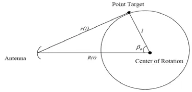
Fig.1 shows a simplified situation for a point target. The distances of the target and the center of rotation to the radar at time t is denoted by r(t) and R(t), respectively. In addition, l and
β
0 are the distance of the target to the center of rotation and initial angle, respectively.Figure 1: Target and radar geometry
Hence, the delay for the echo signal of this point target,
τ
(t), in the above scenario can be written as:)] . cos( . ) 0 ( [ 2 ) ( 2 )
(
ω
β
0τ
= = r −vt−l t−c c
t r
t (1)
)] . cos( . ) 0 ( [ 4 ) ( . 2 ) ( 0
β
ω
π
τ
π
ϕ
− − − − = = − = t l vt r c f t ft (2)
Finally, Doppler spectrum, fD(t), is available as the time derivation of the phase:
)] . sin( [ 2 ) ( 2 1 ) ( 0
β
ω
ω
ϕ
π
− + − − = = = t l v c f dt t d t fD (3)This Doppler spectrum is sum of two major terms. The first one is due to radial motion and has no dependency on time. The second one is time-varying and is due to rotational motion with rate ω:
) . sin( 2 2 )
( = − l
ω
ω
t−β
0 cf c
fv t
fD (4)
If standard motion compensation is performed on the received signal, the effect of radial velocity in Doppler spectrum will be removed. However, Doppler spectrum, which has information about the cross-range position of the scatterer, will be time-varying even in the constant rate rotation. Consequently, this information could be retrieved by proper Doppler processing such as JTFT.
Furthermore, rotation will cause to movement of the scatterer in the range profiles [3]. Polar-reformatting algorithms not only try to reduce these effects but also prepare the condition for using Fourier transform for Doppler processing. However, if the target shows high maneuvering or the total rotated angle becomes large, these methods will fail. Therefore, reconstructed image will be blurred. In this situation or in case of performing only standard motion compensation, time-frequency analysis is a proper option to retrieve information from time-varying Doppler spectrum [4]. It should be noted that using JTFT in SAR has been reported in [4, 9] thought in SAR motion compensation algorithms have better performance than that of in ISAR, because the motion is mainly provided by the radar in SAR.
3. GENERAL SIGNAL MODELING AND IMAGE FORMATION
In this section a general base-band model of the received signal is introduced followed by image formation process.
A. Base-band received signal
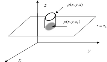
Fig.2 shows a schematic of 2-Dimentional imaging process. Reflectivity of each scatterer is denoted by
ρ
(x,y,z), the reflectivity function, in x,y,z coordination. One may consider 2-D imaging as mapping ofρ
(x,y,z) on a 2-D plane, e.g. z=z0 . In the following,ρ
(x,y,z=z0) is denoted byρ
(x,y) .Figure 2: Schematic of 2-D imaging process and a typical reflectivity function
The range of scatterer locating in (x,y) to the radar, )
(
, t
rxy , becomes:
)) ( sin( )) ( cos( ) 0 ( ) ( ,
, t r vt x t y t
rxy = xy − +
θ
−θ
(5)where
θ
(t) is the instantaneous rotational angle. Similar to (1), in case of performing standard motion compensation, we have:))] ( sin( )) ( cos( [ 2 ) ( 2 ) ( , , t y t x c c t r t xy
y x
θ
θ
τ
− = == (6)
If the transmitted pulse is denoted byS(t), the received echo,Sr(t), due to the target could be expressed theoretically based on superposition principle.
∑
− = y x y xr t x y S t t
S , , ()) ( ). , ( )
(
ρ
τ
(7)By assumption of sinusoidal carrier, Sr(t) within one Pulse Repetition Interval (PRI) becomes:
) , ( ))]}. ( ( 2 Re{exp[ ) ( ,
, t x y
t f j t S y x y x
r =
∑
π
−τ
ρ
(8)So using (6), the base-band received signal, Sr,LP(t), could be written as [4]:
p y x y x y x LP r T c t r t c t r for t y t x c f j y x t S + ≤ ≤ − =
∑
) ( 2 ) ( 2 ))] ( sin( )) ( cos( ( 2 2 exp[ ). , ( ) ( , , ,, ρ π θ θ
(9) where Tp is the PRI. By Defining:
⎪ ⎪ ⎩ ⎪⎪ ⎨ ⎧ = = )) ( sin( 2 ) ( )) ( cos( 2 ) ( t c f t f t c f t f y x
θ
θ
(10))]} ( ) ( [ 2 exp{ ). , ( ) (
,
, t x y j xf t yf t
S
y x
y x
LP
r =
∑
ρ
π
−(11) It has been shown that the above expression can be used for stepped-frequency radars by minor change [4]. In stepped-frequency radar, a burst of pulses with normal time duration will be transmitted instead of very short time duration pulses in order to achieve the desired range resolution. Carrier frequency of each pulse in a burst increases sequentially by step of ∆f [3,4]. Therefore, in (11) f is replaced by fifor the ith pulse in a burst.
Now, we explain (11) in essence. Without loss of generality assume that
θ
(t)=θ
. Hence:)] (
2 exp[ ). , ( ) (
,
, y
y x
x LP
r t x y j xf yf
S =
∑
ρ
π
− (12)In fact, received samples at different times are 2-Dimentional Fourier transform of
ρ
(x,y). Remember thatθ
(t)is time-varying and hence Fourier transform is irrevalent because basis thatρ
(x,y) is decomposed on them are time-varying. In other words, JTFT may be realized as proper tools for reconstruction ofρ
(x,y) [4,7,8].It should be noted that
ρ
(x,y) is the output of a proper mapping which maps radar cross section fromθ
−f plane to the x-y location plane. In case of compensated rotational motion, this mapping is a simple 2-Dimentional Fourier transform [3,5].
B. Image formation method
Assume that radar transmits stepped-frequency waveform containing N bursts which each burst is composed of n conventional pulses; hence N×n pulses will be transmitted within the imaging interval. In the range-gating process received signal is sampled each Tp second. Now, 2-Dimentional matrix G could be organized by filling kthrow of G with samples of kthburst.
Define G1 as standard motion compensated version of G. The sequence of range profiles, G2, taken in various
aspect angles, is available after performing Inverse Discrete Fourier Transform (IDFT) on each row of G1
[3].
Final image will be formed by Doppler processing of columns of G2 . Conventional methods use DFT for Doppler processing:
)
( 2
3 DFT Column G
G = (13)
One may define ISAR image as the absolute value of
3
G [3]. However, the reconstructed image by this process is usually blurred because of rotational motion effects. As it has been stated before, JTFT can resolve time-varying
Doppler spectrum and hence produce better images. Applying JTFT on each column of G2 will generate its
spectrum in M different times in the time-frequency plane. Consequently, a range-Doppler-time cube, G4, will be
organized after applying JTFT for Doppler processing. The final image can be defined as a 2-Dimentional portion of G4 which is taken at an arbitrary time.
)
( 2
4 JointTime FrequencyColumn G
G = − (14)
4. A REVIEW ON STFT
STFT is the most famous and oldest time-frequency transform introduced by Gabor in 1946 [4,11]. It analyzes the frequency content of signal in different time intervals by means of taking Fourier transform of a windowed signal:
∫
∞
∞ −
− −
= g x w x t j x dx t
STFT(
ω
, ) ( ). ( )exp(ω
. ). (15)In other words, at time t, Fourier transform of )
( ). (x w x t
g − is calculated. Hence, time-varying
functions,w(x−t).ejω.x, are the basis of STFT decomposition as opposed to constant time basis of Fourier transform, ejω.x.
One of the most important issues in linear JTFT is Heisenberg uncertainty principle about time-bandwidth product:
5 . 0 ˆ .∆ ≥
∆
ω
ω
(16)where ∆
ω
and ∆ω
ˆ are the effective time duration and effective bandwidth of the kernel function [4]. It shows that both the time resolution and frequency resolution cannot be improved simultaneously. In essence, the more time duration of kernel function, the better frequency resolution will be attained. However, in this case time resolution will be worsen and instantaneous time behavior of signal cannot be realized by STFT [4,12]. On the other hand, short time duration kernel can analyze fast time changing of signal, even though it leads to worsen frequency resolution [4,12]. In addition, smaller time-bandwidth product means that time and frequency resolution trade-off can be handled in a better way [4,12].Therefore, for taking STFT of a signal, one first should choose a proper kernel type in order to achieve the best resolutions simultaneously, i.e., kernel type with smallest time-bandwidth product. Second, its time duration should be adjusted based on the input signal. It has been shown that Heisenberg equality holds only for Gaussian kernel [4]. In fact, for normalized Gaussian kernel we have:
5 . 0 ˆ .
2 1 ˆ
2 2
= ∆ ∆ ⇒ ⎪
⎪ ⎩ ⎪ ⎪ ⎨ ⎧
= ∆
= ∆
ω ω
σ ω
σ
where
σ
2 is the variance of the kernel. Therefore, Gaussian kernel is the best choice for achieving good resolution in time and frequency simultaneously. Consequently, in the following we use Gaussian kernel in STFT for ISAR image formation in order to obtain the best resolutions jointly. Note that in some literatures this kernel is named Gabor kernel and STFT with this kernel is named Gabor transform [4].It should be noted that other linear JTFT such as TFDS and AGR which are investigated in [7,8] require very higher computational load in compared to STFT. Although Discrete Wavelet Transform (DWT) does not impose high processing, it does not possess major advantage in compared to STFT for ISAR image formation because of almost constant rate of Doppler frequency change for scatterers in a specific range cell [12]. On the other hand, the most important bilinear JTFT, WVD, has the best jointly resolutions, even though it introduces cross-terms in the analysis of multi-components signals. Hence, it is not a proper tool for image formation [4,9]. Cohen class transforms, which are based on proper filtering of WVD, are introduced in [7,10] for reducing these cross-terms in WVD. Also, for the same goal, selecting some coefficients of WVD decomposition on specific basis was developed in [8,9] and named as TFDS. In both methods, the resulting JTFT have lower level of cross-terms though they have worse resolution in comparison with WVD [4].
5. ADJUSTING GAUSSIAN KERNEL TIME DURATION USING MINIMUM ENTROPY CRITERION
Two major issues about using STFT for signal analysis are discussed in the previous section. The first one can be handled by selecting Gaussian kernel which satisfies uncertainty principle. The second one, the best duration of kernel, is dependent on the input signal. We will use minimum Entropy criterion for adjusting the best duration of Gaussian kernel in the STFT-based ISAR image formation algorithm. This criterion has been used before in compensation algorithms [5,6,13-16]. Below, the definition of entropy and its conventional use in ISAR is provided followed by the proposed method [12,17].
Entropy of set A is defined as: )
ln( )
( i
A a
i a
a A
H
i
∑
∈ ∀
−
= (18)
where a si are the components of the set and satisfy the condition:
0 : ,
1 ∀ ≥
=
∑
ii
i i a
a (19)
Although this entropy is defined for a probability distribution [18], it can be used for arbitrary vector or matrix in a proper way. For example, consider complex valued matrix I, define its normalized version as:
∑
=j i
j i j i j i
I I I
, 2 ,
2 , ,
~
(20)
Clearly we have:
∑
∑
∑
⎟⎟= ≥ ∀⎟ ⎟
⎠ ⎞
⎜ ⎜ ⎜ ⎜
⎝ ⎛ =
j
i i j
j i
j i
j i
j i j
i I i j
I I I
, ,
, ,
2 ,
2 ,
, 0 , ,
~ , 1 ~
(21)
Therefore entropy could be calculated as: )
~ ln( . ~ )
~
( ,
,
, i j
j i
j
i I
I I
H =−
∑
(22)Entropy has many application and properties which are derived in information theory literatures. For instance, entropy of uniform distribution is maximum and of Dirac distribution is minimum [18].
Similar to the above properties, it has been shown that more focused images have lower entropy [6,13]. Consequently, optimum compensation is attained when entropy of the reconstructed image reaches its minimum. Hence, in ISAR compensation algorithms using entropy criterion, the parameter supposed to be estimated is changed in a reasonable interval and the final estimate of the parameter is selected as the value which will minimize the entropy [6]. It should be noted that the explained method is the easiest one that is based on the direct search while more efficient methods have been developed for ISAR compensation algorithms that can estimate two or three parameters simultaneously with an acceptable amount of processing [6]. Below, we will use similar idea for the STFT based ISAR image formation.
Here, we will obtain the optimum duration of Gaussian kernel at the point in which the entropy of the reconstructed image is minimum. Therefore, the most focused image will be formed by Gaussian kernel with this duration. In other words, the duration of Gaussian kernel is changed in a reasonable interval and at each fixed duration, STFT Doppler processing will be performed on the columns of G2; then, entropy of
reconstructed image is calculated. Finally, the duration which is corresponded to the minimum entropy will be selected as the optimum duration for Gaussian kernel and will be used for image formation.
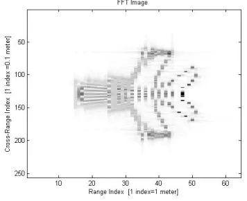
kernel locally instead of adjusting it totally. In other words, the proposed algorithm can be performed on each column of G2which should be processed individually. It has been expected that the local adjustment of the duration result in the better performance than that of for conventional method; this exception is compatible with simulation results shown in Figs. 3,4, and 5. These figures show the reflectivity function (the original image), the reconstructed image by FFT, and the reconstructed image by STFT using local adjustment of Gaussian kernel, respectively. Samples are simulated based on an X-band stepped-frequency radar with 9 GHz average carrier, 65 pulses per each of 256 bursts, burst bandwidth equals to 156 MHz, imaging interval equals to 2 seconds, and total rotated angle equals to 9 degrees. With these parameters, this radar have 1 (m), 0.1 (m) resolutions in the range and cross-range respectively [19-21].
Figure 3: Original image (simulated reflectivity function)
Figure 4: Reconstructed image by Fourier Transform
Figure 5: Reconstructed image by STFT using local adjustment of Gaussian kernel
6. COMPARISON BY NORMALIZED CORRELATION PARAMETER
There are many different methods for ISAR image formation; some of them are very similar to each other due to minor differences. In this situation, a quantitative parameter is required for comparison of reconstructed images by various methods because human eye cannot properly justify them.
A normalized correlation parameter can be used in the simulation for the comparison of reconstructed images by different methods [12,17,26]. Indeed, in the simulation, some samples are generated based on the determined reflectivity function, original image. Hence, the differences between original image, Iorg, and the reconstructed image, Iisar, can be expressed as:
2 ,
) ) , ( ) , ( (
isar isar
j
i org
org
E j i I E
j i I
D=
∑
−(23)
where Eorg and Eisar are the energy of the original and reconstructed image, respectively. One may write (23) as:
⎪ ⎪ ⎩ ⎪ ⎪ ⎨ ⎧
=
− = −
=
∑
∑
) , ( ). , ( 1
2 2 ) , ( ). , ( 2
2
, ,
j i I j i I E E R
R j
i I j i I E E D
org j
i isar org isar
org j
i isar org isar
⎪⎭ ⎪ ⎬ ⎫
⎪⎩ ⎪ ⎨ ⎧
− −
=
∑
j i
isar org
org isar q
p E E I i j I i p j q
R
,
, (, ). ( , )
1
max
(25) where p and q shifting parameters in the range and cross-range directions. It should be noted that the normalized correlation parameter can be used only in the theory and simulation, because in the real world the original image is not available.
Normalized correlation parameter for simulated samples in the previous section are 0.385 for Fourier transform, 0.522 for STFT using total adjustment of duration, and 0.591 for STFT using local adjustment of Gaussian kernel duration. These quantities confirm better performance of the STFT-based Doppler processing specifically in local adjustment of kernel duration.
Fig. 6 shows normalized correlation parameter versus various total rotated angles. Although all methods have similar behavior when total rotation is small, they will be different by increasing rotation obviously. Also, STFT with local kernel duration adjustment has the best performance among the investigated methods specifically the conventional ISAR image formation, Fourier transform.
Figure 6: Comparison of different ISAR image formation method without noise
Now, we assume that the received signal, y(t), is sum of the desired signal, Sr,LP(t), and white Gaussian noise,
) (t
n , in the base-band [22-25]:
) ( ) ( )
(t S, t n t
y = rLP + (26)
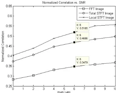
Fig. 7 shows the normalized correlation parameter versus various SNRs at a fixed total rotated angle equals to 9 degrees. As expected, the performances of all methods have been decreased in compared with the ideal situation which is free of noise. In addition, the proposed method has the best performance even in low SNR.
Figure 7: Noise effect on the performance of methods
7. CONCLUSION
Doppler spectrum in ISAR imaging is time-varying even in the rotation with a constant rate. Hence, reconstructed image by means of Fourier transform will be blurred if polar-reformatting algorithms either failed or did not use. JTFT, which are good for time-varying spectrum analysis, can produce more focused images. In linear JTFT such as STFT adjusting duration of the kernel function plays an important role in the final performance based on uncertainty principle. In this paper we propose an STFT-based ISAR image formation method that uses minimum entropy criterion to achieve the best duration of Gaussian kernel. This criterion is used in both total and local cases. Simulation results show that STFT-based image formation using local adjustment of kernel duration has much better performance than conventional image formation methods even in low SNR and large rotated angles.
8. REFERENCES
[1] Gonzales, R. C.; Woods, R. C.; digital image processing, 2nd Edition, Prentice Hall, 2002.
[2] Mensa, D. L.; High resolution radar cross-section imaging, 2nd Edition, Artech house, 1991.
[3] Wehner, D. R.; High resolution radar ,2nd Edition , Artech house , 1994.
[4] Chen, V. ; Ling, H.; Time-Frequency transform for radar imaging and signal analysis, Artech house, 2002.
[5] Son,S. J.;Thmas, G.;Flore, C. B.;Range Doppler radar imaging and motion compensation, Artech house, 2000.
[6] Xi, L. ;Guosui, L. ; Ni, J.; “Autufocusing of image based on entropy minimization”, IEEE Transaction on Aerospace and Electronic Systems, Vol. 35,No.4 ,pp. 1240-1251, 1999.
[8] Chen, V. ;”Reconstruction of inverse synthetic aperture radar image using adaptive time-frequency wavelet transform”, SPIE Proc. On wavelet Applications, Vol.2494 pp. 373-386, 1995. [9] Kersten, P.R.; Jansen, R.W.; Luc, K.; Ainsworth, T.L.;
“Implementation of the time-frequency distribution series for SAR applications”, Proceedings of IEEE International Conference on Geosciences and Remote Sensing Symposium, pp. 3587-3590, 2006.
[10] Zhu, Y.; Wang, H.; Xiao, S.; “Application of Adaptive Kernel Time-Frequency Distribution in ISAR”, 9th International Conference on Signal Processing, 2008.
[11] Oppenheim, A. V.; Schafer, R. W.; Buck, J. R.; Discrete time signal processing, 2nd Edition, Prentice- Hall, 1999.
[12] M. Dorostgan; Joint time-frequency transfoms for ISAR imaging, M.Sc Thesis (In Persian), ECE Department, Isfahan University of Technology, 2004, (in Persian)..
[13] Ho, R. J.; Hyo, T. K.; Kyung, T. K.; “Application of Subarray Averaging and Entropy Minimization Algorithm to Stepped-Frequency ISAR Autofocus”, IEEE Transaction on antennas and propagation, Vol. 56, No. 4, 2008.
[14] Zhu, D.; Wang, L.; Yu, Y.; Tao, Q.; Zhu, Z.; “Robust ISAR range alignment via minimizing the entropy of the average range profile”, IEEE Geoscience and remote Sensing letter, vol. 6, no. 2, pp. 204– 208, Apr. 2009.
[15] Cao, P.; Xing, M.; Sun, G.; Li, Y.; Bao, Z.; “Minimum Entropy via Subspace for ISAR Autofocus”, IEEE geoscience and remote sensing letters, Vol. PP, pp. 1-5, 2009.
[16] Martorella, M.; Berizzi, F.; Bruscoli, S.; “Use of Genetic Algorithms for Contrast and Entropy Optimization in ISAR Autofocusing”, EURASIP Journal on Applied Signal Processing, 2006.E. H. Miller, "A note on reflector arrays," IEEE Trans. Antennas Propagat., to be published.
[17] M. Dorostgan, M. Modarres-Hashemi, S. Sadri; Optimizing STFT based ISAR image formation using entropy and contrast criteria, ICEE, 2005, (in Persian).
[18] Cover, T. M. ;Thomas, J. A. ; Elements of information theory, John Wiley & sons, 1991.
[19] Chen, V.;Miceli, W. J. ; “Simulation of Isar imaging of moving targets”, IEE proc.-Radar, sonar and navigation, Vol. 148, No.3, pp. 160-166, 2001.
[20] Hua, Y. ; Baqai, E. ; Zhu, Y. ; “Imaging of point scatterers from step-frequency ISAR data”, IEEE Transaction on Aerospace and Electronic Systems, Vol. 29,No. 1,pp. 195-204, 1993.
[21] Shirman, Y. D. ;Computer simulation of aerial target radar scattering, recognition, detection and tracking, Artech house, 2002. [22] Zwieg, G.; “Super-resolution Fourier transforms by optimisation,
and ISAR imaging”, IEE Proc.-Radar ,Sonar and navigation, Vol. 150, No. 4, 2003.
[23] Popovic, V.; Thayaparan, T.; Stankovic, L.; “Noise analysis of the high resolution methods in ISAR”, Proceedings of the 4th International Symposium on Image and Signal Processing and Analysis, 2005.
[24] Kovaci, M.; Isar, D.; Isar, A.; “Denoising SAR images”, International Symposium on Signals, Circuits and Systems, 2003. [25] Nuthalapati, M. R. ; “High resolution construction of ISAR
images”, IEEE transaction on aerospace and electronic, Vol. 28, No. 2, 1992.