Analysis and Design of Institutional Building by Cype Software
Mahendra Swamy
1, Dr.Sridhar R
2, Amarnatha S N
3*(Department of Civil Engineering,Nagarjuna College of Engineering and Technology, Bengaluru, India) **(Department of Civil Engineering,Nagarjuna College of Engineering and Technology,Bengaluru , India)
***(FE designs,Civil Engineer / CYPE Dealership, Bengaluru, India)
1.
Introduction
Every human has desire to own comfortable house and on an average, generally one spends his two-third of lifetime in the house. Therefore there is an increased trend towards the construction of multi-storeyed buildings for residential as well as for non-residential purposes in the urban areas. Hence nowadays the building construction has become a major work which indicates the social progress of the county. In order to compete with the ever growing competent market it is very important for a structural engineer to save time. It is emphasized that any structure to be constructed must satisfy the need efficiently for which it is intended and shall be durable for its desired life span. But in the modern scenario, it is not possible to analyze sophisticated structures manually, as even a structure of modest proportion involves many skills and literally hundreds of different operations. This calls for the use of specialized software packages for the efficient planning, analysis, design, drafting, estimation and project management. “CYPECAD” is one such software which has been used for analysis of complicated structures more efficiently and rapidly.
1.1 Wind Loading Criteria
Wind is air in motion relative to the surface of the earth. The primary cause of wind is traced to earth‟s rotation and differences in terrestrial radiation. The radiation effects are primarily responsible for convection either upwards or downwards. The wind generally blows horizontal to the ground at high wind speeds. Since vertical components of atmospheric motion are relatively small, the term „wind‟ denotes almost exclusively the horizontal wind, vertical winds are always identified as such. The wind speeds are assessed with the aid of anemometers or anemographs which are installed at meteorological observatories at heights generally varying from 10 to 30 metres above ground. Very strong winds (greater than 80 km/h ) are generally associated with cyclonic storms.
Basic Wind Speed basic wind speed map of India, as applicable to 10 m height above mean ground level for different zones of the country. Basic wind speed is based on peak gust velocity averaged over a short time interval of about 3 seconds and corresponds to mean heights above ground level in an open terrain (Category 2).
2.
Software details
2.1. Cypecad
This project involves analysis and design of multistoried [G + 4] residential building using a design software CYPECAD. We have chosen CYPECAD because of its following advantages:
i. Program that carries out the analysis and design of reinforced concrete and steel structures, subject to horizontal and vertical loads, for homes, buildings and civil project works.
Abstract:
Nowadays the building construction has become a major work which indicates the social progress of the county. In order to compete with the ever growing competent market it is very important for a structural engineer to save time. “CYPECAD” is one such software which has been used for analysis of complicated structures more efficiently and rapidly. The present project deals with the wind load analysis and design of a institutional building is Madhwa‟s wadiraj college of Engineering, Civil engineering block, Udupi, building consisting of 6 floors by considering wind load parameter using “CYPE software. The analyse and design of various structural elements of the structure has been carried out by wind load taken as per IS-875(Part -3),for dead load and live load taken as per IS-875(Part-1,Part-2) using CYPE software, design and detailing , reports of all Columns, Beams, Slabs, staircase taken from cypecad.ii. Its use guarantees maximum analysis reliability and optimum drawing design. iii. The geometry of the structure can be introduced automatically.
iv. The user can personalize the design and edit the elements that have been introduced,with the on-screen support provided such as, help options and error and warning texts.
v. Provides very complete and precise construction drawings of the structure. vi. CYPECAD is adapted to the latest national and international construction codes. vii. Seismic analysis with force amplification.
viii. From model generation, analysis and design to visualization and result verification,CYPECAD is the professional‟s choice for steel, concrete, timber, aluminium and cold-formed steel design of low and high-rise buildings, culverts, petrochemical plants, tunnels, bridges, piles and much more.
3.
Projectdetails
3.1 Salient features
Utility of buildings: Educational building
Location : Madhwa‟s wadiraj college of Engineering Civil engg block, Udupi No of Floors : 6 floors
No of staircase : 1 in each floor Type of contraction :RC framed structure
3.2 Geometric Details Floor to floor height: 4m Thickness of wall: .0.230m
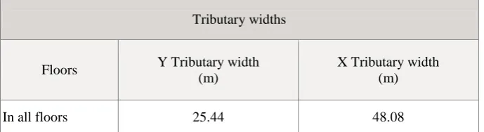
Table 1: Tributary Widths Tributary widths
Floors Y Tributary width (m)
X Tributary width (m)
In all floors 25.44 48.08
Materials used :Grade of concrete : M25
Table 2: Materials Used
Element Concrete fck
(MPa) c
Maximum size of the aggregate (mm)
Ec
(MPa)
All M 25 25 1.50 20 25000
The all concrete properties as shows in the Table 2 Grade of steel: FE500
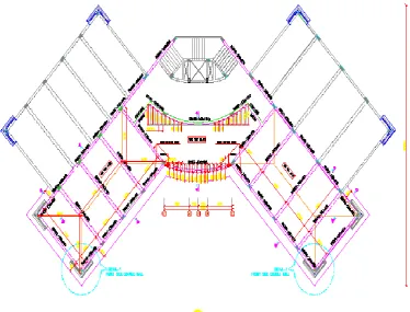
Fig 1 : Plan View
4.
Methodology
Modeling in CYPECAD involves following steps: i.) Automatic job introduction
ii.) Specifying structure details.
iii.) Importing of architectural drawings. iv.) Specifying loads on the structure. v.) Defining Structure geometry.
vi.)Defining special loads on the structure.
such that it fulfills the software requirements. Editing of drawing involves creating layers which indicates the positioning of columns and its dimensions. These different floor drawings which are edited are imported to the softwarefor further modeling. dimensions. These different floor drawings which are edited are imported to the softwarefor further modeling.
After Modeling we perform the analysis part without foundation and the analysis is done by a method known as Stiffness matrix method. Once the structure is modeled we select the appropriate foundation for the structure based on trial and error method, for our project we found that isolated footing is safe with bearing capacity of soil assumed as 200KN/m2. A vast amount of analysis and reinforcement options are available to be able to take into account those aspects that are deemed most adequate. Additionally, for each structural element and each reinforcement position, personalized reinforcement tables may be defined. For all design elements, their geometry and reinforcement can be edited and modified, with multiple tools to carry out the task. Drawings can be personalized according to the user‟s needs, as the program allows configuring all the drawing layers and elements and generating them via DXF, DWG, printer and plotter.
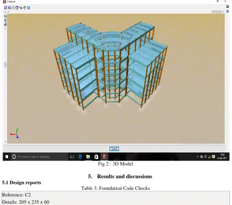
Fig 2 : 3D Model
5.
Results and discussions
5.1 Design reports
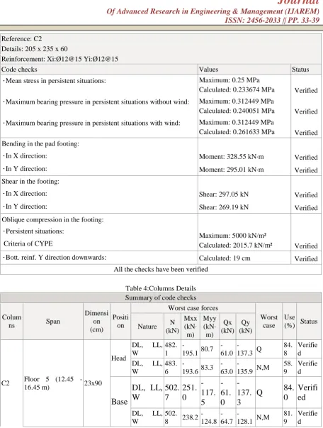
Table 3: Foundation Code Checks Reference: C2
Details: 205 x 235 x 60
Reinforcement: Xi:Ø12@15 Yi:Ø12@15
Code checks Values Status
Reference: C2
Details: 205 x 235 x 60
Reinforcement: Xi:Ø12@15 Yi:Ø12@15
Code checks Values Status
- Mean stress in persistent situations: Maximum: 0.25 MPa
Calculated: 0.233674 MPa Verified - Maximum bearing pressure in persistent situations without wind: Maximum: 0.312449 MPa
Calculated: 0.240051 MPa Verified - Maximum bearing pressure in persistent situations with wind: Maximum: 0.312449 MPa
Calculated: 0.261633 MPa Verified Bending in the pad footing:
- In X direction: Moment: 328.55 kN·m Verified - In Y direction: Moment: 295.01 kN·m Verified Shear in the footing:
- In X direction: Shear: 297.05 kN Verified - In Y direction: Shear: 269.19 kN Verified Oblique compression in the footing:
- Persistent situations: Criteria of CYPE
Maximum: 5000 kN/m²
Calculated: 2015.7 kN/m² Verified - Bott. reinf. Y direction downwards: Calculated: 19 cm Verified
All the checks have been verified
Table 4:Columns Details Summary of code checks
Colum
ns Span
Dimensi on (cm)
Positi on
Worst case forces
Worst case
Use (%) Status Nature N
(kN) Mxx (kN· m) Myy (kN· m) Qx (kN) Qy (kN)
C2 Floor 5 (12.45 - 16.45 m) 23x90
Head
DL, LL, W
482. 1
-195.1 80.7 -61.0
-137.3 Q
84. 8
Verifie d DL, LL,
W
483. 6
-193.6 83.3 -63.0
-135.9 N,M 58. 9
Verifie d
Base
DL, LL,
W
502.
7
251.
0
-117.
5
-61.
0
-137.
3
Q
84.
0
Verifi
ed
DL, LL, W
502. 8 238.2
-124.8
-64.7
-128.1 N,M 81. 9
Fig 3: Frame1
Table 5: Slabs (Floor 2)
Moments Steel areas Additional reinf.
Slab Dir. Depth Left Centre Right Left Centre Right Top Left Bot. Centre Top Right L4 X
Y 0.15 43.67 15.64 9.23 6.49 7.78 6.76 14.65 5.25 3.10 2.18 2.61 2.27 Ø20@20 Ø12@20 Ø10@25 Ø[email protected] Ø[email protected] Ø8@20 L2 X
Y 0.15 29.19 5.42 8.49 7.40 7.34 2.88 9.79 1.82 2.85 2.48 2.46 0.97 Ø16@20 Ø8@25 Ø[email protected] Ø8@20 Ø8@20 Ø8@25 L3 X
Y
0.15 5.09 64.77 2.85 9.32 3.99 5.75 1.71 21.72 0.95 3.13 1.34 1.93 Ø8@25 Ø[email protected] Ø8@25 Ø10@25 Ø8@25 Ø8@25 L1 X
Y
0.15 3.87 27.52 7.71 8.49 3.09 11.03 1.30 9.23 2.59 2.85 1.04 3.70 Ø8@25 Ø16@20 Ø[email protected] Ø[email protected] Ø8@25 Ø10@20
6.
Conclusions
1.
Analysis and Design conducted using CYPECAD satisfies the permissible deflection limit.2.
Analysis and design by using CYPECAD consumes less time hence this can be highly useful for quicker work &time bound projects.4.
Removal of columns changes entire reinforcement patterns, orientations, shape of beam columns slabs, footing.5.
5. By removal of columns C9, C11,C23 &C25, Deformations of building, bending moments, Shear force of nearby removal columns of the structural members will get changed.6.
By removal of columns C9, C11,C23& C25 ,maximum and minimum moments and shear forces in the Beams Frame14,15,9,28,4,25,37,15 and 8 has been changed.Columns C2,C10,C12,C13,C15,C16,C29,C32,C24 & C37 also changed in the moments and shear along with X,Y axis.References
[1]. Santhosh Kumar D,Anusha B Rao, Greeshma.Roshan S. Kotian, Swathi Shetty “Analysis And Design Of Multi-Storeyed Reinforced Concrete Building Using CYPECAD” ,July 2016
[2]. B. Ragavendar, G.Saravanan “Progressive Collapse Analysis of RC Multi-Story Building”IJSRD - International Journal for Scientific Research & Development| 2016
[3]. Chintha Santhosh, Venkatesh Wadki, S.Madan Mohan, S.Sreenatha Reddy “Analysis and Design of Multistory Building Using ETABS”Vol. 5, Issue 9, September 2016
[4]. Mrs. Mir Sana Fatema, Prof. A.A. Hamane “Progressive Collapse of Reinforced Concrete Building”(Nov. - Dec. 2016)
[5]. Amar Hugar, Sharanabasappa M Pujari, Beerappa G Pujari, Anaveerappa N Biradar, Gajendra “Analysis and Design of a Commercial cum Residential Building By Using STAAD Pro”2016
[6]. Syed Asaad Mohiuddin Bukhari*, Shivaraju G D, Ashfaque Ahmed Khan “Analysis of progressive collapse in rc frame structure for different seismic zones”: june, 2015
[7]. B. Gururaja R. Sridhar „Progressive Collapse Potential of Irregular Concrete Building‟ IOSR Journal of Mechanical and Civil Engineering (IOSR-JMCE) (ICAET 2014)
[8]. PROF. KAWADE U. R., MS. VIDYA V MHASKE “Progressive collapse analysis of existing rc buildings using linear static analysis”Vol. 3 Issue 4 March 2014
[9]. Samrat Prakash Khokale “Progressive Collapse of High Rise R.C.C. Structure under Accidental Load” March 2014
[10]. Bhavik R. Pate “Progressive Collapse Analysis of RC Buildings Using NonLinear Static and Non-Linear Dynamic Method”, September 2014
[11]. A.R. Rahai, M. Banazadeh, M.R. Seify Asghshahr & H. Kazem “Progressive Collapse Assessment of RC Structures under Instantaneous and Gradual Removal of Columns” 2012
[12]. CYPE Ingenieors, Cypecad – user‟s manual, 2009
[13]. IS 456:2000-BUREAU OF INDIAN STANDARDS, manak bhavan, 9 bahadur shah zafar marg, New Delhi.