Swati A. Zingade and Kshitij R. Bhavsar
1
Civil Engineering, DYPIEMR Akurdi 2
Mechanical Engineering, Sapkal COE, Nashik
Abstract
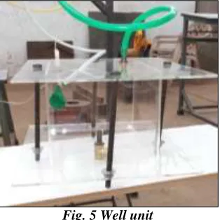
Solar water pumps are a cost-effective and dependable method for providing water in situations where water resources are spread over long distances; power lines are few or non-existent; or fuel and maintenance costs are considerable. There are several methods for pumping water in remote areas, such as windmills, gas/diesel pumps, and ram pumps. But most of these options are either too expensive to install, or for fuel and maintenance, or require specific site conditions to operate solar pumps can work for most locations and are at full capacity when needed most: during warm, sunny days. In temperate regions, they can be used year-round—which can be particularly helpful for potable water, animal grazing, and other farming operations. In present study, the cylindrical parabolic plate collector has used on to which sun rays will be incident, evacuated tube collector (ETC) is used to convert water into steam form. The steam generated is then passed in boiler unit, where the steam will get pressurized. This high pressure steam is then passed over the below. This creates compression of bellow hence pressure gets generated on the other side of the piston. This air pressure is then passed in the balloon which is incorporated in the well unit. The well unit is full of water hence volume of water in the well unit get increased and hence required suction lift is created. Hence pumping can be achieved. Experimental study was able to lift 0.5 m water at 2 m height with average peak temperature of 310 °C and 0.078 bar pressure. 0.5 m water. This would be the most economical way of pumping.
Keywords: Cylindrical Parabolic plate collector, ETC, Well unit, Pressure unit etc.
I. INTRODUCTION
Energy from the sun travels to the earth in the form of electromagnetic radiation similar to radio waves, but in a different frequency range. Available solar energy is often expressed in units of energy per time per unit area, such as watts per square meter (W/m2). The amount of energy available from the sun outside the earth’s atmosphere. As a result, on a clear day the amount of solar energy available at the Earth’s surface in the direction of the sun is typically 1000W/m2
There is need for harnessing clean sources or non-conventional sources of energy. Solar energy is clean source of energy. The amount of pollution generated by solar energy is negligible. Solar energy is easily available. Solar is harnessed by using certain appliances which have the ability to store the energy.
A cylindrical solar concentrator is one such application which not only stores the energy but also distributes it uniformly throughout the surface. In this project we have used a cylindrical parabolic reflector along with a pressurizer and well unit in order to pump water without the use of electricity.
II. METHODOLOGY
The set-up mainly consisting of six components collecting tank, parabolic reflector, ETC tube, steam pressurizer, single acting cylinder and well unit.
A. Components of the experimental set-up
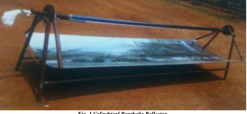
A.1 Cylindrical parabolic reflector: The point concentration with the help of parabolic reflector does not give the sufficient heat so as to generate specific pressure to lift the water [1]. Thus the line concentrator used as cylindrical parabolic reflector. The parabola is set of points equidistant from fixed point known as focus and a fixed line called as directrix. A cylindrical parabolic reflector or line concentrator looks like half cut section of a cylinder as shown in fig.1.The dimensions of the parabolic reflector are in the order of 8ft × 3 ft. In this project a cylindrical parabolic reflector plays a crucial role of reflecting and projecting the reflected rays on the absorbing part i.e. ETC located at focal point of the reflector. Parabolic cylindrical reflector are specially used a line concentration which heat the line of fluid throughout the length. This help in preventing the loss of heat in the pipe. Resulting in uniform heating of pipe throughout the length. This parabolic reflector can be made highly effective by using silver paper coating on it. 1 kW of energy is generated in 1 m² [2]
Fig. 1 Cylindrical Parabolic Reflector
Fig. 2 Evacuated Tube Collector
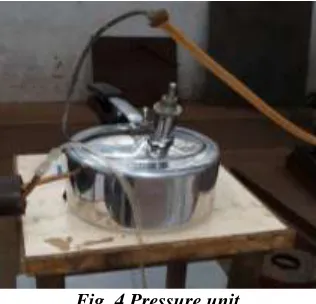
A.3 Pressure unit: For experiment purpose pressure cooker was used available in market; only the whistle was replaced by dead weight safety valve with spring loaded safety valve. This spring loaded safety valve transmit the steam directly over the piston.
Fig. 4 Pressure unit
A.4 Piston cylinder Assembly: For piston cylinder assembly the rubber bellow were used. It has a nature to regain its original shape when force is removed. This bellow separates the air which is supplied to well unit and steam supplied to piston cylinder assembly. For demonstration purpose, wooden pistons were used as it is light material. Cylinder have 80mm diameter, 200 mm length & length of piston is 30mm
Fig.5 Piston Cylinder Assembly
Fig. 5 Well unit
A.6 Tracking mechanism: A manual tracking mechanism was given by using a disc having diameter of 180 mm with 15 mm diameter holes drilled at an angel of 45° w.r.t. each other at 3 points on each disc as shown in fig. 6.
Fig. 6 Manual Tracking Mechanism
B. Experimental set-up
III. RESULT & DISCUSSION
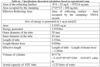
A. Theoretical Analysis: Based on actual experimental set-up the theoretical calculation were made those are mention in tale no. 1
Table no. 1 Specifications theoretical calculations based on experimental setup Area of the reflecting Surface 8*4 = 32 sq.ft = 9753.6 sq.mm Area occupied by the clamping 2*15*15 = 450 sq.mm
Effective Reflecting Area Area of reflecting surface – Area occupied by the clamping= 9303.6 sq.mm
1kw of energy is generated in 1 sq.m area[2]
Area 3.5555 sq.m
Energy generated 3.5555kw
Outer diameter of the tube 55 mm Inner diameter of the tube 45 mm
Length of tube 2.334m
Length Heater hose 0.050m
Effective length Length of tube – Length of heater hose = 2.284m
Volume of cylinder Pi*r2*h =3.1415*45*45*2284 =0.01453 cubic m
Actual capacity of ETC tube =3.25 litres of water
B. Experimental analysis
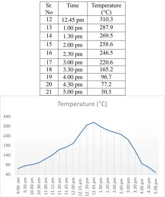
B.1 Temperature Readings: Digital thermometer was attached to ETC tube so as to observe the temperature change of water inside. Table no. 2 shows average range of temperatures on due scheduled times which are taken over a couple of months. Change in temperature was recorded every after 30 min. started from 9 am to 5 pm. As temperature goes above 100°C; temperature change was recorded every after 15 min interval till achievement of peak temperature. As shown in fig 8. At 9 am water temperature was recorded as around 70.6°C. and it was gradually increases which reached at its peak temperature of around 310.3 ° C at 12.45 pm. Again it was gradually decreased by the time.
Table 2. Average temperature observed during day time
Sr. No
Time Temperature (°C)
1 9.00 am 70.6
2 9.30 am 85.2
3 10.00 am 90.6
4 10.30 am 100.4
5 11.00 am 120.6
6 11.15 am 141.1
7 11.30 am 169.3
8 11.45 am 181.8
9 12.00 pm 198.0
10 12.15 pm 210.1
Fig. 8 Profile of Temperature change
B. 2 Pressure and height calculation: The provided height to uplift the water was 2 m. thus theoretically required pressure was calculated and it was observed as 1.2132 bar. The detail calculations of theoretical pressure required is given below.
The lift height for the experiment is 2m As we know
P = ρ*g*h = 1000*9.81*2 = 19620 N/m2
= 0.1962 bar 0.2 bar The atmospheric pressure is 1.0132 bar
Hence total applied pressure =1.0132+ 0.2= 1.2132 bar (Theoretical) Where,
P = Pressure of water in waterline ρ = Density of water
g = Acceleration due to gravity h = Height
From the above discussion it can be said that the ready expansion of balloon can be achieved when the 40 90 140 190 240 290 340 9 .0 0 a m 9 .3 0 a m 1 0 .0 0 a m 1 0 .3 0 a m 1 1 .0 0 a m 1 1 .1 5 a m 1 1 .3 0 a m 1 1 .4 5 a m 1 2 .0 0 p m 1 2 .1 5 p m 1 2 . 3 0 p m 1 2 .4 5 p m 1 .0 0 p m 1 .3 0 p m 2 .0 0 p m 2 .3 0 p m 3 .0 0 p m 3 .3 0 p m 4 .0 0 p m 4 .3 0 p m 5 .0 0 p m
Temperature (°C)
Sr. NoTime Temperature (°C) 12 12.45 pm 310.3
13 1.00 pm 287.9
14 1.30 pm 269.5
15 2.00 pm 258.6
16 2.30 pm 246.5
17 3.00 pm 220.6
18 3.30 pm 165.2
19 4.00 pm 96.7
20 4.30 pm 77.2
But due to various losses; pressure gauge reading achieved at the inlet of balloon was 0.07848 bar (Experimental)
Considering experimentally achieved pressure; theoretical water lift height can be calculated as bellow. As we know,
P = ρ*g*h
h =
ρ
=
= 0.8m
Hence theoretically 0.8 m water must have pumped.
In practical observations, around 0.5 m water was able to lift this could be due to the wet steam gets impinged into the balloon due to leakages resulting into the formation of moisture inside the balloon. This ultimately affects the lift of water. Ideally, after the generation of temperature the steam would get generated in the boiler unit. But due to lack of superheated steam the required pressure is not getting developed. For the same purpose the boiling unit needs to be heated which can be achieved by integrating it with a parabolic reflector which could generate continuous heat. The pressure loss is mainly observed due to the pipe which attaches boiler unit and inlet on piston cylinder.
IV. CONCLUSION
For many sites, a solar pump is often the best option for reducing cost and labor. Domestic water supplies for off-grid homes and cabins. Although solar water pumps are used in this application, usually the home has an existing power system. In present study of solar pumping system, the required peak average temperature was observed around 310.3 °C at noon period but due to various losses corresponding pressure gain was 0.0780 bar. Hence the achieved water lift was around 0.8 m. For better efficiency of this system we required thrust pressure at regular intervals. Slight modifications in design of pressurizer unit and piston material (e.g. aluminum) will reduces pressure and other losses and allow more water to lift upward.
BIBLIOGRAPHY
[1] Malusare S. Et.al “ Solar Powered Water Pump” A report 2007-08 Finolex Academy of Management & Technology, Ratnagiri
[2] Sukhatme P. “ Solar Energy” Tata Mc-Graw-Hill, New Delhi, 1984, pp 315-335
[3] A report on Solar PV Applications in India, published by Center for Study of Science, Technology and Policy (2006-07)
[4] Odeh, I, Yohanis, Y.G., and Norton, B. Economic viability of photovoltaic water pumping systems. Solar Energy 80 [2006], pp. 850-860, www.sciencedirect.com
[5] Kamel, K. and Dahl, C. The economics of hybrid power systems for sustainable desert agriculture in Egypt. Solar Energy [2005], pp. 1271-1281, www.sciencedirect.com
[6] Cuadros, F., Lopez-Rodriguez, F., Marcos, A. and Coello, J. A procedure to size solar-powered irrigation [photoirrigation] schemes. Solar Energy 76 [2004], pp. 465-473, www.sciencedirect.com.
[7] Foster, R.E., Gupta, V.P. and Sanchez-Juarez, A. Field Testing of CdTe PV Modules in Mexico. ASES Solar 2006: Renewable Energy: Key to Climate Recovery. Jul. 8-13, 2006, Denver, CO, 6pp..
[8] Daud, A.-K. and Mahmoud, M. M. Solar powered induction motor-driven water pump operating on a desert well, simulation and field tests. Renewable Energy 30 [2005] pp. 701-714,
[9] Clark, R.N. Photovoltaic water pumping for livestock in the Southern Plains. American Society of Agricultural Engineers Paper No. 94-4529, 1994.
[10] Vick, B.D. and Clark, R.N. Comparison of Solar Powered Water Pumping systems which use Diaphragm Pumps. ASES 2007: Sustainable Energy Puts America to Work. July 7-12, Cleveland, OH, 6 pp.
[11] Clark, R.N. and Vick, B.D., Performance Comparison of Tracking and Non-Tracking Solar Photovoltaic Water Pumping Systems, American Society of Agricultural Engineers. 1997, ASAE Paper No. 97-4003,
[12] Clark, R.N., Vick, B. D., and Ling, S., Remote water pumping using a 1 kilowatt solar-PV AC system, American Society of Agricultural Engineers Paper No. 98-4087, 1998, 12 pp.