Journal of Hydraulic Structures
Department of Civil Engineering
Faculty of Engineering
Shahid Chamran University of Ahvaz
In the name
of GOD
JORNAL OF
HYDRAULIC
STRUCTURES
SHAHID CHAMRAN UNIVERSITY OF AHVAZ
Manager: Prof. Hamid R. Ghafouri
Editor-in-chief: Dr. Ali Haghighi
Editorial coordinator:Dr. Seyed Mohammad Ashrafi Department of Civil Engineering, Faculty of
Engineering, Shahid Chamran University of Ahvaz, Ahvaz, Iran.
Members
Prof. Hossein M. V.Samani
Civil Engineering Department, Shahid Chamran University of Ahvaz, Ahvaz, Iran
Prof. Hamid R. Ghafouri
Civil Engineering Department, Shahid Chamran University of Ahvaz, Ahvaz, Iran
Dr. Ali Haghighi
Civil Engineering Department, Shahid Chamran University of Ahvaz, Ahvaz, Iran
Prof. Mahmood S. Bajestan
Hydraulic Structures Department, Shahid Chamran University of Ahvaz, Ahvaz, Iran
Prof. Saeed R. S. Yazdi
Civil Engineering Department, K.N.Toosi University of Technology, Tehran, Iran
Dr. Mohammad S. Pakbaz
Civil Engineering Department, Shahid Chamran University of Ahvaz, Ahvaz, Iran
Dr. Arash Adib
Civil Engeering Department, Shahid Chamran University of Ahvaz, Ahvaz, Iran
Dr. Mojtaba Labibzadeh
Civil Engineering Department, Shahid Chamran University of Ahvaz, Ahvaz, Iran
Prof. Helena M. Ramos
Instituto Superior Técnico (IST), University of Lisbon
Dr. S. Mohammad Ashrafi
Civil Engineering Department, Shahid Chamran University of Ahvaz, Ahvaz, Iran
Dr. S. Abbas Haghshenas
Institute of Geophysics, University of Tehran | UT, Tehran, Iran
Dr. Mohammad Zounemat-Kermani
Department of Water Engineering, Shahid Bahonar University of Kerman, Kerman, Iran
Dr. Taher Rajaee
Civil Engineering Department, University of Qom, Qom, Iran
Dr. Mohammad Vaghefi
Civil Engineering Department, Faculty of Engineering, Persian Gulf University, Bushehr, Iran
Dr. A. A. Telvari
Soil Conservation and Watershed Management Research Institute; Department of Civil Engineering, Islamic Azad University, Ahvaz branch, Ahvaz, Iran
CONTENTS
VOL 4, Issue 2, Autumn 2018
I.
In the name of God
II. Table of Contents
III. Aims and Scope
01
A Mass Conservative Method for Numerical
Modeling of Axisymmetric flow
R. Asadi
10 Development of A new Hydraulic
Relationship for Submerged Slide Gates
S. Jahan Kohan; Hossein M.V. Samani; H. Ebrahimi
17 Effect of rice husk ash on the swelling
pressure of bentonite soil stabilized with
lime in the presence or lack of sulfate
Mohammad S. Pakbaz; S. SeyedAlizadeh Ganji
27 Characteristic Based Split Finite Element
for Unsteady Dam-Break Problem
J. Parsa
42 Boundary Integral Equations for
Quasi-Static Unsaturated Porous Media
E. Jabbari; M. Behnia
60 Evaluating performance of meta-heuristic
algorithms and decision tree models in
simulating water level variations of dams’
piezometers
Aims and Scope
Hydraulic Structure Journal is an interdisciplinary journal which publishes high-quality peer-reviewed articles addressing the latest developments and applied methods in construction, maintenance, management, and operation policy of Hydraulic Structures.
The Journal aims at providing an efficient route to fast-track publication, within 10-12 weeks after manuscript submission. Manuscripts will be considered for publication in the following categories: research articles, technical notes, case reports and discussions.
The general areas covered by the Journal include:
Technical and methodological advances in application, design/selection, production, modification of construction materials
Advances in numerical and analytical methods
Hydro informatics and soft computing
Hydraulic aspects of hydraulic structures
Applied surface and subsurface hydrology and hydrometeorology
Forecasting approaches in water resources engineering
Economic and social aspects of hydraulic structures
Uncertainty analysis and risk management in hydraulics and water resources engineering
Application of Nanotechnology in Hydraulic Structures
Geotechnics of Hydraulic Structures
Damage detection techniques
The following might be considered as hydraulic structures:
Dams and associated structures
River and Watershed Structures
Offshore and Onshore Structures
Irrigation and Drainage Channel Networks
Bridges
Water Storage and Conveyance Structures
Pipelines and Pump Stations
Sewerage Systems
Water and Wastewater Treatment Plants
Historical Water Structures
General Information
Title: Journal of Hydraulic Structures
Subject: Hydraulics and water resources engineering
Coverage area: International
Journal Type: Scientific and technical
License Holder: Shahid Chamran University of Ahvaz
Editor-in-Chief: Dr. Ali Haghighi
Manager: Prof. Hamid R. Ghafouri
Editorial coordinator: Dr. Seyed Mohammad Ashrafi
Language Editor:
Dr. Mohammad Azizipour
Address: Department of Civil Engineering, Faculty of Engineering, Shahid Chamran University of Ahvaz
Phone #: +986133330011-19 (5610 & 5603)
Fax #: +986113337010
Language: English
Email: [email protected]
Journal of Hydraulic Structures
J. Hydraul. Struct., 2018; 4(2):1-9 DOI: 10.22055/JHS.2018.26273.1080
A Mass Conservative Method for Numerical Modeling of
Axisymmetric flow
Roza Asadi1
Abstract
In this paper, the axisymmetric flow toward a pumping well has been numerically solved by the cell-centered finite volume method. The numerical model is discretised over unstructured and triangular-shaped grid which allows simulating inhomogeneous and complex-shaped domains. Due to the non-orthogonality of the irregular grids, the multipoint flux approximation (MPFA) schemes are used to discretize the flux term. In this work, the diamond scheme as the MPFA method has been employed and the least square method is applied to express the full discrete form of the vertex-values of the hydraulic head. The scheme has been verified via the Theis solution, as a milestone in well hydraulics. The numerical results show the capability of the developed model in evaluating transient drawdown in the confined aquifers. The proposed numerical model leads to the stable and local conservative solutions contrary to the standard finite element methods. Also this numerical technique has the second order of accuracy.
Keywords: Axisymmetric radial flow, Cell-centered finite volume method, MPFA method, Diamond scheme.
Received: 11 March 2018; Accepted: 29 Jun 2018
1. Introduction
Groundwater accounts for about 30 percent of the world's supply of fresh water. In arid and semi-arid regions this resource serves as an alternative to the surface reservoirs of water. These issues make well hydraulics an important aspect in hydrological and water science problems. The mathematical analysis of well pumping on head decline in confined aquifers first provided by Theis in 1935 [1]. The analytical solutions for other types of aquifers such as leaky and unconfined aquifer were obtained by Hantush and Jacoub [2] and Neuman [3-6], respectively. However, the analytical solutions are limited to the ideal cases. Thus, numerical methods have been developed to model the real and complicated circumstances. Despite the traditional numerical schemes such as the standard finite element method developed extensively to model the groundwater problems, it suffers from the numerical oscillations especially in inhomogeneous porous media [7-10]. In order to resolve the numerical instabilities and provide
1 Department of Civil Engineering, K.N. Toosi University of Technology, Tehran, Iran, [email protected]
mass conservative solution, the finite volume methods (FVMs) have been formulated to simulate the groundwater flow equation [10-15]. Since the unstructured grid is the most efficient and flexible mesh to model the complex geometries and sharp heterogeneities [16], this type of mesh is applied in this study. Due to non-orthogonality of the irregular grids, MPFA schemes are used to discretize the flux term [17,18]. In this work, the diamond scheme as the MPFA method has been employed on the unstructured triangular grids [19-23]. Moreover, the least square method is applied to express the full discrete form of the vertex-values of the hydraulic head. This procedure results in the cell-centered finite volume method (CC-FVM). It was demonstrated in [15, 21] that this scheme provides second-order accurate solutions.
In [13], this discretization scheme was combined with the mechanics equation to simulate the Biot's model [24] in two-dimensional domain. It was illustrated that the proposed numerical method result in stable and local conservative solutions. In addition, it was shown that the unstructured grid makes the model well-suited for simulating heterogeneous domains and complicated geometries [13].
The axisymmetric flow toward a pumping well has been numerically solved by the cell-centered finite volume method. Since the computational cost of the axially symmetric model is less than the equivalent three dimensional one, this simplification has been assumed in the formulations. Indeed, in this study the effectiveness of the model in simulating flow in confined aquifer subjected to pumping has been investigated.
2. Mathematical formulation
The governing equation for fluid flow in a confined aquifer is:
𝑆𝑠𝜕ℎ
𝜕𝑡+ div𝐯 = 𝑓 (1)
where 𝑆𝑠 is the specific storage coefficient which can be defined as 𝜌𝑤𝑔(𝛼 + 𝑛𝛽), 𝐯 = 𝐊̅∇ℎ is the Darcy's velocity, ℎ denotes the hydraulic head and 𝐊̅ is the tensor form of the hydraulic conductivity. t is time, 𝜌𝑤 denotes the density of fluid, 𝑛 is the porosity and 𝛼 and 𝛽 are the compressibility of aquifer and fluid, respectively. Finally, 𝑓 is a sink /source term.
The required boundary conditions can be written as follows:
ℎ = ℎ𝐷 on 𝛤ℎ (2)
𝐯. 𝐧 = 𝑞 on 𝛤𝑞 (3)
where ℎ𝐷 and 𝑞 are the boundary values of the hydraulic head and flux, respectively. The unit normal vector 𝐧is pointing outward from the boundaries which are defined as:
𝛤ℎ∪ 𝛤𝑞 = 𝜕Ω (4)
𝛤ℎ∩ 𝛤𝑞 = ∅ (5)
3. Numerical model
A detailed description of the numerical formulations is presented in this section. For this purpose at the first stage, the FVM method has been applied for discretizing the flow equation and then a diamond scheme has been implemented to approximate the flux term. As mentioned earlier the variation of the hydraulic properties in the angular direction has been neglected and the model simulates the planar domain.
3.1.1 The CC-FVM
A Mass Conservative Method for Numerical Modeli … 3
∫ (𝑆𝑠𝜕ℎ
𝜕𝑡 + div𝐯) 𝑑V Vi
= ∫ 𝑓𝑑V V𝑖
(6)
where in the above equation 𝑑V is the volume element which is defined as 𝑟𝑑𝑟𝑑𝜃𝑑𝑧 in the cylindrical coordinates. For the axisymmetric case the above equation can be reduced to the double integral as follows:
∫ 𝑟 (𝑆𝑠𝜕ℎ
𝜕𝑡+ div𝐯) 𝑑Ω Ωi
= ∫ 𝑟𝑓𝑑Ω Ω𝑖
(7)
where 𝑑Ω is the area element such that 𝑑Ω = 𝑑𝑟𝑑𝑧, Ωi denotes the two dimensional control volume and 𝑟 and z are the radial and axial coordinates, respectively. By implementing theorem of Gauss–Green to Eq. (7), the integral form of the flow equation will read as:
∫ 𝑟 (𝑆𝑠𝜕ℎ 𝜕𝑡) 𝑑Ω Ωi
− ∫ 𝐧. 𝐊̅∇ℎ 𝜕Ωi
𝑟𝑑Γ = ∫ 𝑟𝑓𝑑Ω Ωi
(8)
The symbols 𝜕Ωi denotes the control volume's boundary. With approximating hydraulic head and the source/sink term at the centroid of the control volumes, the discretized form of the flow equation is obtained as follows:
𝑟̅𝑆𝑠𝜕ℎ𝑖
𝜕𝑡 |Ωi| + ∑ 𝑟𝑒𝑉𝑖𝑗|Γ𝑖𝑗| Γ𝑖𝑗𝜖𝜕Ωi
= 𝑟̅𝑓𝑖|Ωi| (9)
in which ℎ𝑖 is cell-averaged value of the hydraulic head. Γ𝑖𝑗 is the internal edge between two adjoining cells (Ωi and Ωj) and the absolute value of Γ𝑖𝑗 (|Γ𝑖𝑗|) represents its length. 𝑉𝑖𝑗 denotes the flux across this edge and |Ωi| is used to present area of the control volume. 𝑟̅ and 𝑟𝑒 denote the radial distances from the cell center and the midpoint of the edge Γ𝑖𝑗. 𝑓𝑖 indicates the cell average of the sink/source term.
The velocity term is discretized with the equation proposed by Coudière et al. [20]:
𝑉𝑖𝑗= − 1 |Γ𝑖𝑗|
∫ 𝐧. 𝐊̅∇ℎ Γ𝑖𝑗
𝑑Γ (10)
Figure 1. Symbols used in the numerical formulations
3.1.2 Approximating flux integral
As mentioned earlier, a diamond scheme as a multipoint flux approximation is applied to evaluate the flux at the interface of the cells. In this procedure, the gradient of hydraulic head is calculated with the values of head at the vertices and center of the cells [18-20, 22, 25]. Indeed, using only cell center values of hydraulic head result in inaccurate solution for the unstructured grids [18, 25]. The gradient of hydraulic head across the boundary Γ𝑖𝑗 is given by [13, 15, 19, 20, 23]:
𝝍𝑖𝑗 = (ℎ𝑗− ℎ𝑖
𝐷𝑖𝑗 − cot 𝜃
ℎ𝐽− ℎ𝐼 |Γ𝑖𝑗| ) 𝐧ij+
ℎ𝐽− ℎ𝐼
|Γ𝑖𝑗| 𝐭ij (11)
In the above equation, 𝐧ij indicates the unit normal of Γ𝑖𝑗 and is assumed that pointing from i to j (Fig. 2), and 𝐭ij is the tangent vectors of the respective face. As illustrated in figure 2, ℎ𝑖 and ℎ𝐼 are the head values at the centroid of cell 𝑖 and vertex 𝐼, and ℎ𝑗 and ℎ𝐽 are the corresponding values at the center of the control volume 𝑗 and node 𝐽, respectively. As shown in Fig.2, the parameter 𝐷𝑖𝑗 is defined as 𝐷𝑖𝑗= 𝑑𝑖𝑗+ 𝑑𝑗𝑖, in which 𝑑𝑖𝑗 and 𝑑𝑗𝑖 are the length of the lines between points 𝑖 and 𝑗 and the cell face, respectively [13, 15, 19, 20, 23]. Other parameters in Eq.(11) are illustrated in Fig.(2).
Figure 2. Parameters used in the multipoint flux stencil
h
iJ
I
K
Ω
iΓ
ijV
ijh
jΩ
jr
ir
er
z
i
j
I
d
ijd
ji
θ
n
ijA Mass Conservative Method for Numerical Modeli … 5
Combining Eq. (10) and (11), yields the full discrete form of flux as [13, 19, 20]:
𝑉𝑖𝑗 = −𝜿𝝍𝑖𝑗. 𝐧ij (12)
In the above equation, the conductivity tensor 𝜿 is the full matrix which can be expressed as follows [13, 19, 20]:
𝜿 = 1 |Γ𝑖𝑗|∫ 𝐊Γ𝑖𝑗̅
𝑑Γ = [𝜅𝜅𝑛𝑛 𝜅𝑛𝑡
𝑡𝑛 𝜅𝑡𝑡] in (𝐧ij, 𝐭ij) (13)
By substituting Eqs. (10) and (12) into Eq. (11), the numerical flux reads as [13, 19, 20, 23]:
𝑉𝑖𝑗= −𝜅𝑛𝑛ℎ𝑗− ℎ𝑖
𝐷𝑖𝑗 − (𝜅𝑛𝑡− cot 𝜃𝜅𝑛𝑛)
ℎ𝐽− ℎ𝐼
|Γ𝑖𝑗| (14)
Finally by interpolating head values at vertices in terms of the cell center values, the FV discretization will be completed [18, 20]. Averaging procedure for computing the weight factors is the least squares algorithm [15, 19-22]. By applying this averaging procedure, ℎ𝐼 is calculated as follows:
ℎ𝐼= ∑ 𝑤𝑖ℎ𝑖 𝑁𝐼
𝑖=1
(15)
The above summation is done over the cells common to the point I, and the weighting function 𝑤𝑖 is defined for any control volume sharing vertex 𝐼 as [13, 19, 20]:
𝑤𝑖 =1 + 𝛬𝑟(𝑟𝑖− 𝑟𝐼) + 𝛬𝑧(𝑧𝑖− 𝑧𝐼)
𝑁𝐼+ 𝛬𝑟𝑅𝑟+ 𝛬𝑧𝑅𝑧 (16)
where 𝑟𝑖 and 𝑟𝐼 are the radial distances of the cell center 𝑖 and vertex 𝐼, respectively. 𝑧𝑖 and 𝑧𝐼 denote the vertical distances of 𝑖 and 𝐼 from the z-axis. Also the following equations are used to formulate other functions in Eq. (16) [13, 19, 20]:
𝛬𝑟 =
𝐼𝑟𝑧𝑅𝑧− 𝐼𝑧𝑧𝑅𝑟
𝐼𝑟𝑟𝐼𝑧𝑧− 𝐼𝑟𝑧2 (17)
𝛬𝑧 =
𝐼𝑟𝑧𝑅𝑟− 𝐼𝑟𝑟𝑅𝑧
𝐼𝑟𝑟𝐼𝑧𝑧− 𝐼𝑟𝑧2 (18)
𝐼𝑟𝑟= ∑(𝑟𝑖− 𝑟𝐼)2 𝑁𝐼
𝑖=1
(19)
𝐼𝑧𝑧= ∑(𝑧𝑖− 𝑧𝐼)2 𝑁𝐼
𝑖=1
(20)
𝐼𝑟𝑧= ∑(𝑟𝑖− 𝑟𝐼) 𝑁𝐼
𝑖=1
(𝑧𝑖− 𝑧𝐼) (21)
𝑅𝑟 = ∑(𝑟𝑖− 𝑟𝐼) 𝑁𝐼
𝑖=1
(22)
𝑅𝑧 = ∑(𝑧𝑖− 𝑧𝐼) 𝑁𝐼
𝑖=1
By substituting Eqs. (15) and (16) into Eq.(14), the final discrete form of this equation can be obtained. The similar procedure has been performed for all faces of each control volume to complete discretization of Eq.(9).
4 Numerical result
To verify the proposed scheme, the Theis solution has been solved and the numerical results have been compared with the analytical solutions. The validation demonstrates the effectiveness of the numerical technique for modeling the radial flow toward wells in confined aquifers. Moreover, to construct the triangular grids, NETGEN algorithm has been implemented as the mesh generator tool [26] and all of the numerical codes have been written in MATLAB 2010 software.
The first analytical solution for the drawdown problem in the confined aquifer was derived by Theis (1935) [1]. To simplify the problem the following assumptions have been made in the Theis solution:
1. The confined aquifer is considered as a homogeneous, isotropic porous media and has infinite horizontal extent.
2. The piezometric surface is considered horizontal prior to pumping.
3. The well is fully penetrated and the pumping rate is constant.
4. The radial flow towards well is horizontal.
5. The radius of the pumping well is very small.
6. The layer has uniform extent and confined top and bottom.
7. Water is released from the porous media as head declines [27, 28].
These conditions are illustrated in Fig. 3. With the above assumptions, the drawdown 𝑠′ is calculated as [27, 28]:
𝑠′= 𝑄 4𝜋𝑇∫
𝑒−𝑦 𝑦 ∞
𝑢
𝑑𝑦 (24)
where𝑄 is the pumping rate, 𝑇 denotes transmissivity, the parameter 𝑢 is defined as 𝑟
2𝑆
4𝑇𝑡 and 𝑆 is the storage coefficient [27,28].
Figure 3. Schematic of the Theis problem
A Mass Conservative Method for Numerical Modeli … 7
Table 1. Hydraulic parameters of the porous medium
Parameters Values
Thickness of the aquifer 25 𝑚
Horizontal extent 500 𝑚
Pumping rate 𝑄 = 0.2 𝑚3/𝑠𝑒𝑐
Transmissivity 𝑇 = 6.37 × 10⁻²𝑚2/𝑠𝑒𝑐
Storage coefficient 𝑆 = 8.49 × 10⁻⁴
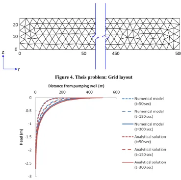
The computational mesh is shown in Fig.4. In Fig.5, the numerical and analytical solutions are compared. As illustrated in Fig. 5, numerical results closely correspond to the analytical solutions.
Figure 4. Theis problem: Grid layout
Figure 5. Theis problem: comparison between numerical and analytical solutions
5. Conclusions
This study presents a mass conservative method to model the axisymmetric groundwater flow toward a pumping well. Since the MPFA methods use head values in more than two cells in the unstructured grids, applying this scheme improves the accuracy of the result.
0 450 500
0 10 20
r
Furthermore, the diamond method has been implemented to construct the flux expression in terms of head values at the vertices and cell centers. Moreover, to interpolate the hydraulic values at the vertices, the least square method has been applied. Finally, to investigate the efficiency of the proposed numerical scheme, the model is verified against the Theis solution as a milestone in well hydraulics. The result illustrates that the model successfully simulates the transient drawdown in the confined aquifers.
References
1. Theis CV (1935) The relation between the lowering of the piezometric surface and the rate and duration of discharge of a well using ground-water storage. Transactions American Geophysical Union, 16, 519–24.
2. Hantush, MS, Jacob CE (1955) Non-steady radial flow in an infinite leaky aquifer. Eos, Transactions American Geophysical Union, 36(1), 95-100.
3. Neuman SP (1972) Theory of flow in unconfined aquifers considering delayed gravity response. Water Resources Research 8(4), 1031–1045.
4. Neuman SP (1973) Supplementary comments on theory of flow in unconfined aquifers considering delayed gravity response. Water Resources Research 9(4), 1102–1103.
5. Neuman SP (1974) Effect of partial penetration on flow in unconfined aquifers considering delayed gravity response. Water Resources Research 10(2), 303–312.
6. Neuman SP (1975) Analysis of pumping test data from anisotropic unconfined aquifers. Water Resources Research, 11(2), 329–345.
7. Vermeer PA, Verruijt A (1981) An accuracy condition for consolidation by finite elements. International Journal of Numeical and Analytical Methods in Geomechanics, 5(1), 1-14.
8. Murad MA, Loula AFD (1992) Improved accuracy in finite element analysis of Biot’s consolidation problem. Computer Methods in Applied Mechanics and Engineering 95(3), 359–382.
9. Ferronato M, Castelletto N, Gambolati G (2010) A fully coupled 3-D mixed finite element model of Biot consolidation. Journal of Computational Physics, 229(12), 4813–4830.
10. Kim J (2010) Sequential methods for coupled geomechanics and multiphase flow. PhD thesis, Stanford University.
11. Asadi R, Ataie-Ashtiani B (2015) A comparison of finite volume formulations and coupling strategies for two-phase flow in deforming porous media. Computers and Geotechnics, 67, 17-32.
12. Asadi R, Ataie-Ashtiani B, Simmons CT (2014) Finite volume coupling strategies for the solution of a Biot consolidation model. Computers and Geotechnics, 55, 494-505.
13. Asadi R, Ataie-Ashtiani B (2016) Numerical modeling of subsidence in saturated porous media: A mass conservative method. Journal of hydrology, 542, 423-436.
A Mass Conservative Method for Numerical Modeli … 9
15. Manzini G, Ferraris S (2004) Mass-conservative finite volume methods on 2-D unstructured grids for the Richards’ equation. Advances in Water Resources, 27(12), 1199-1215.
16. Lee SH, Jenny P, Tchelepi HA (2002) A finite-volume method with hexahedral multiblock grids for modeling flow in porous media. Computers and Geosciences, 6(3-4), 353-379.
17. Edwards MG (2002) Unstructured, control-volume distributed, full-tensor finite-volume schemes with flow based grids. Computational Geosciences, 6(3-4), 433-452.
18. Szymkiewicz A (2012) Modelling water flow in unsaturated porous media: accounting for nonlinear permeability and material heterogeneity. Springer Science & Business Media.
19. Coudière Y, Villedieu P (2000) Convergence rate of a finite volume scheme for the linear convection-diffusion equation on locally refined meshes. Mathematical Modelling and Numerical Analysis, 34(6), 1123-1149.
20. Coudière Y, Vila JP, Villedieu P (1999) Convergence rate of a finite volume scheme for a two dimensional convection–diffusion problem, Mathematical Modelling and Numerical Analysis, 33, 493–516.
21. Bertolazzi E, Manzini G (2004) A cell-centered second-order accurate finite volume method for convection–diffusion problems on unstructured meshes. Mathematical Models and Methods in Applied Sciences, 14(8), 1235-1260.
22. Bertolazzi E, Manzini G (2005) A unified treatment of boundary conditions in least-square based finite-volume methods. Computers & Mathematics with Applications, 49(11), 1755-1765.
23. Bevilacqua I, Canone D, Ferraris S (2011) Acceleration techniques for the iterative resolution of the Richards equation by the finite volume method. International Journal for Numerical Methods in Biomedical Engineering, 27(8), 1309-1320.
24. Biot MA (1941) General theory of three-dimensional consolidation. Journal of Applied Physics, 12, 155–164.
25. Edwards MG, Rogers C (1998) Finite volume discretization with imposed flux continuity for the general tensor pressure equation. Computers & Geosciences, 2(4), 259–290.
26. Schöberl J (1997) NETGEN An advancing front 2D/3D-mesh generator based on abstract rules. Computing and Visualization in Science, 1(1), 41-52.
27. Fetter CW (1994) Applied Hydrogeology, third ed. Prentice Hall, New Jersey.
28. Bedient PB, Rifai HS, Newell CJ (1994). Ground water contamination: transport and remediation. Prentice-Hall International, Inc.
Journal of Hydraulic Structures
J. Hydraul. Struct., 2018; 4(2):10-16 DOI: 10.22055/JHS.2018.13760
Development of A new Hydraulic Relationship for Submerged
Slide Gates
Sasan Jahan Kohan1 Hossien M. V. Samani2 Hossein Ebrahimi3
Abstract
Slide gates are one of the most common gates used in hydraulic structures. These gates are often in practice hydraulically submerged. The usual method to determine the flow passes through the gate is solving simultaneously the energy and the momentum nonlinear equations by a numerical method. In this manuscript, a large number of various cases of gate sizes and flows are considered and solved numerically by using these two equations to obtain a database. This database is converted to dimensionless groups and then a direct relationship is developed by using three-dimensional curve fitting. The results obtained by the developed relationship are compared with those obtained by the numerical common method. The comparison results in a good agreement which indicates that the developed relationship is accurate and simple to be used in the design of slide gates.
Keywords: Slide gate, Numerical method, Submerged gate, Curve fitting.
Received: 18 February 2018; Accepted: 21 September 2018
1. Introduction
Slide gates are common in irrigation networks, used for controlling the flow in channels. The flow passes the gate may result in either a free or submerged hydraulic jump when interacts with the tailwater. The outflow is said to be free when the issuing jet of the supercritical flow is open to the atmosphere and is not submerged. The outflow is known as submerged, if the tailwater
1 Water Resources Engineering Department, Faculty of Engineering, Shahre Qods Islamic Azad
University, Shahr Qods, Tehran, Iran, [email protected]
2 Water Resources Engineering Department, Faculty of Engineering, Shahre Qods Islamic Azad
University, Shahr Qods, Tehran, Iran , [email protected] (Corresponding author)
3 Water Resources Engineering Department, Faculty of Engineering, Shahr Qods Islamic Azad University,
Development of A new Hydraulic Relationship for … 11
depth,
y
3is greater than the conjugate depth needed to form a hydraulic jump. The commonly observed case is the submerged one. Figures 1 and 2 show the free and submerged hydraulic jumps, respectively.Henry [1] conducted experiments on free and submerged slide gates and showed the
experimental results in terms of the gate flow coefficient,
C
d as a function of G yy1 and
G y
y3 . Rao
and Rajaratnam [2] also showed a good accord between theory and experiment for the case of submerged flow from a culvert which is similar to the case of the submerged flow from the slide gate.
Rajaratram and Subramaniya [3] have developed the following equation for gates in which free hydraulic jumps occur:
1
2
gy
by
C
Q
d G (1)Figure 1. Free hydraulic jumpin a slide gate
Figure 2. Submerged hydraulic jump in a slide gate
In which Qis the flow discharge passes through the gate,
C
dis the gate flow coefficient, b is the gate width,y
G is the gate opening,y
1 is the flow depth upstream the gate,y
2is the contracted jet depth going out the gate opening, y is the water depth just behind the gate, andy
3is the taiwater depth. Rajaratnam [4] proved that the gate flow coefficient is a function of
1
/
y
proved that
C
dhas the form shown in Equation (3). Swamee [6] obtained Equation (4) for the coefficientC
d.1
1641
.
0
6468
.
0
y
y
C
Gd
(1)1 6108 . 0 1 6108 . 0 y y C G d (2) 072 . 0 1 1
15
.
0
611
.
0
G G dy
y
y
y
C
(3)Swamee [7] in his research has shown that the flow coefficient in submerged gates depends on the tailwater depth in addition to the gate opening and the flow depth upstream of the gate. Ferro [8] and Negam et al., [9] et al. studied the case of the simultaneous flow over and under the gate. Negam [10] developed equations to determine the combined flow over a weir and under the gate.
No direct explicit equation has been developed to calculate the flow through submerged gates. In this research, a new direct explicit relationship to calculate the flow in terms of the gate dimensions, upstream flow depth, gate opening, tailwater depth is developed.
2. Materials and methods
2.1. Traditional common method
The flow discharges pass through the gate can be found by the traditional common method in which the energy equation between upstream and cross section 2 and the momentum equation between this cross-section and the tailwater depicted in Figure 2 are solved simultaneously. The energy and momentum equations are given in Equations (5) and (6), respectively:
2 2 2 2 1 2 1
)
(
2
)
(
2
g
by
Q
y
by
g
Q
y
(5)in which
y
2
0
.
61
y
G)
(
2
)
(
)
(
)
(
2
3 2 3 3 2 2by
g
Q
by
y
by
g
Q
by
y
(6)The nonlinear Equations (5) and (6) are solved by using the solver in Excel program to obtain the unknowns Q and y.
Development of A new Hydraulic Relationship for … 13
m
b
m
y
m
y
s
m
Q
10
5
.
0
7
.
9
04
.
0
10
05
.
0
/
100
05
.
0
3 1 3
Some of the results by the above-explained traditional method are given in Table 1.
Table 1. Some of the results obtained by the traditional method for submerged gates
2.2 The developed equation using non-linear optimization
The involved variables in the problem are converted to dimensionless groups by using dimensional analysis. The resulted dimensionless groups are as follows:
3 2
1 3
1
(
)
,
,
G Gby
g
b
Q
and
y
y
y
y
3 2)
(
by
Gg
b
Q
is considered as a function of 1 y yG and 1 3 y y
. Many types of functions with unknown
coefficients are regarded and by using the Generalized Reduced Gradient (GRG) nonlinear optimization method, the function which results in the best fit in which the summation of the squares of the differences between the obtained function and the given points is minimized. The type of the function which results in the maximum correlation coefficient was as given in the following:
3 3
2 3
2
1 1
3 3 3
3 2 3 2
1 1 1
1 1 1 1 1
11.37 11.03 9.81
10.4 2.31 10.25 21.16 0.184 17.92 9.51
( G) G G G G G
y y
Ln Ln Ln
y y
y y y
Q B
Ln Ln Ln
y y y
g by y y y y y y y y y y
2 3 1 1 G y y y y (7)
The correlation coefficient, r2, of the function given in Equation (7) is equal to 0.9997 which indicates that the developed equation is accurate enough to be used for the design of the
y1(m)
b(m) yG(m)
y3 (m)
Q(m3/s) y(m)
y2 (m)
submerged slide gates.
3. Results and conclusions
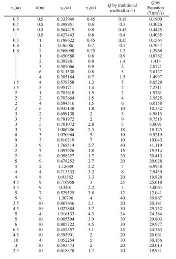
The results of the developed relationship given in Equation (7) are compared with those obtained by the traditional method in which the energy and momentum equation are solved simultaneously in Table 2 for a wide range of gate dimensions and hydraulic conditions.
Table 2. Comparison of the discharges obtained by the traditional method and Equation (7)
y1(m) b(m) yG(m) y3(m)
Q by traditional method(m3/s)
Q by Equation (7)(m3/s)
0.5 0.5 0.333949 0.45 0.18 0.1909
0.7 0.5 0.398951 0.6 0.3 0.3026
0.9 0.5 0.564419 0.8 0.45 0.4425
1 0.5 0.427442 0.8 0.4 0.4035
0.5 1 0.188622 0.45 0.15 0.1564
0.8 1 0.46586 0.7 0.7 0.7047
0.8 2 0.568098 0.75 1.3 1.2968
1 1 0.450588 0.8 0.9 0.8782
1 2 0.392881 0.8 1.4 1.414
1 3 0.507066 0.9 2 2.0721
1 6 0.311538 0.8 3 3.0127
1 4 0.205164 0.7 1.5 1.4997
1.5 4 0.578758 1.2 5 5.0528
1.5 5 0.951711 1.4 7 7.2311
2 1 0.703618 1.5 2 1.9761
2 2 0.703664 1.5 4 3.9525
2 4 0.584516 1.5 6 6.0158
2 6 0.935148 1.8 10 10.332
3 2 0.699138 2 5 4.9815
3 3 0.781972 2 9 8.7515
3 5 0.701072 2.8 5 5.0091
3 7 1.006286 2.5 18 18.125
6 3 1.070964 5 10 9.9219
9 3 0.810219 7 10 10.043
3 9 1.768514 2.7 40 41.119
2 7 1.097926 1.8 15 15.514
2 9 0.958327 1.7 20 20.413
5 9 0.478252 2.7 20 20.028
4 2 1.12689 3.2 7 6.9948
4 4 0.713533 3.2 8 7.9459
4 8 0.91582 3.3 20 19.828
4.5 9 0.710958 3 25 25.018
2.5 9 0.3401 2.2 5 5.0064
5 7 0.529525 3.8 12 12.041
5 9 1.30796 4 40 39.867
2.5 10 0.867646 2.1 20 20.181
4.5 10 1.027884 3.7 30 29.752
5 4 1.916133 4.3 24 24.384
5 10 0.905594 3.9 30 29.803
6 10 0.805722 4.5 30 29.977
6.5 10 0.452357 3.1 25 24.763
4.5 10 0.395901 2 20 20.061
10 4 1.052254 5 30 30.156
3 10 0.593473 2 20 20.013
Development of A new Hydraulic Relationship for … 15
3 10 0.657484 2.5 15 14.858
7 3 0.716452 5.4 8 8.029
7 6 1.054521 5.7 22 21.913
7 7 0.371009 5.8 8 7.9331
8 7 2.143786 7 50 49.674
8 8 1.689877 7.5 30 30.013
9 8 1.900035 7 70 69.517
9 9 0.841116 7.7 25 25.168
8 4 3.419684 7.4 40 41.392
9 10 2.529361 8 85 84.564
10 8 1.028664 6 50 50.082
5 10 1.099075 4.6 22 21.911
7 10 1.808016 6 60 59.577
8 10 2.110436 7 70 69.566
10 6 1.121588 7 35 35.067
10 10 1.80164 8 80 79.425
10 10 3.411529 9.3 100 101.46
Referring to Table 2 , the results of the comparison show that the discharges calculated by the traditional method and proposed method (Equation (7)) are very close to each other. The developed equation is an explicit equation which can be used directly to calculate the flow discharge through submerged slide gates in a much easier manner compared to the traditional method in which two nonlinear equations must be solved simultaneously. Hence, the developed equation can be used in the design of submerged slide gates directly due to its simplicity and high accuracy.
References
1. Henry, H. R. (1950). Discussion on "Diffusion of submerged jets, "by Albertson, M. L. et al., Trans. Am. Society Civil Engrs., 115, 687.
2. Raeo, G., Rajaratnam, N. (1963). " The submerged hydraulic jump, " Proc. Am. Soc. Civil Engineers, 89(1), 139.
3. Rajaratnam, N. and Subramaniya, K. (1967). "Flow equation for sluice gates. J. Irrig. Drainage Eng., ASCE, 93:167-186.
4. Rajaratnam, N. (1977). "Free flow immediately below sluice gates," J. Hydraul. Eng. ASCE, 103(3): 345-351.
5. Garbrecht, G. (1977). “ Discussion of discharge computation at river control structures.” J. Hydr. Div., 104(12), 1481-1484.
6. Swamee, P. K. (1992). "Sluice gate discharge equations," J. Irrig. Drainage. Eng., 118: 57-60.
7. Swamee, P. K. (1988). "Generalized rectangular weirs equations," J. Hydraul. Eng., ASCE 114: 945-949.
8. Ferro, V. (2000). " Simultaneous flow over and under the gate," J. Irrig. and Drainage Eng., ASCE, 126(3): 190-193.
10. Negam, A. M. (2002). "Combined free flow over the weir and below Gates," J. Hydraul. Res., IAHR, 40(3): 359-365.
Journal of Hydraulic Structures
J. Hydraul. Struct., 2018; 4(2):17-26 DOI: 10.22055/JHS.2018.26403.1082
Effect of rice husk ash on the swelling pressure of bentonite soil
stabilized with lime in the presence or lack of sulfate
Mohammad Siros Pakbaz1 Saber Seyedalizadeh Ganji2
Abstract
Lime is an effective substance to decrease the swelling of expansive soils. The effective use of lime as a stabilizing agent in the presence of sulfate under some circumstances has been questioned due to the formation of ettringite. In this research, the effect of the addition of rice husk ash (RHA) on the swelling pressure of a bentonite soil (B) modified with lime (L) and calcium sulfate or gypsum (G) was investigated. Nine groups of twin compacted samples, namely, bentonite soil (B), B + L (3% by dry weight), B+3%L+ 5%G, B+3%L+RHA (5, 10 and 15% by dry weight, respectively) and B+3%L+5%G+RHA (5,10 and 15%, respectively), were prepared and tested immediately for 1-D constant volume swelling pressure measurements. Similar groups of samples were prepared and tested after 7 and 28 days of curing. The results indicated the effect of RHA in decreasing the magnitude of swelling pressure in comparison with untreated and treated soil without RHA.
Keywords: Rice husk, Lime, Sulfate, Expansive soil, Swelling pressure.
Received: 01 July 2018; Accepted: 21 September 2018
1. Introduction
The stabilization of expansive clay soils with cementitious materials such as ordinary Portland cement and lime has been practiced over the past six decades (e.g. [1-8]). The decrease in swelling potential of treated soils with lime is due to the flocculation of soil particles as a result of exchanging Ca2+ cations with other cations present on the surface of the clay minerals, which causes a reduction in tendency for double layer expansion. The second reason for the decrease in swelling potential upon blending lime or cement with expansive soils is due to pozzolanic reactions that occur with time between silicates and aluminates that are detached from the surface of clay minerals and calcium ions present in the solution. The silicates and aluminates are dissociated from the clay mineral surfaces when under alkaline conditions
1 Department of Civil engineering. Faculty of Engineering, Shahid Chamran University of Ahvaz , Iran,
[email protected] (Corresponding author)
2 Department of Civil engineering. Faculty of Engineering, Shahid Chamran University of Ahvaz , Iran,
(pH>12) in the presence of lime or cement in excess of 3% of the soil dry weight [9].
Occasionally, the use of lime or cement for treating expansive soils rich in sulfate-bearing minerals has caused more expansion. This expansion is due to the formation and subsequent hydration of minerals ettringite and / or thaumasite. The Ca2+ ions in the calcium-based stabilizers participate with alumina released from clay minerals and with sulfate in the presence of water to form ettringite and/or thaumasite [10-17]. Pakbaz and Keshani [18] showed that the presence of 5 to 10% of gypsum caused the initial generation of higher magnitudes of swelling pressure compared with those of untreated bentonite soil and bentonite soil treated with 3% of lime.
In several countries such as Iran, India, and Thailand, there are many agricultural waste materials produced, such as rice husk (RH) that are mostly dumped or used as fuel. Rice husk is produced during the milling process of rice and consists approximately 22% of the weight of the rice (Rice Market Monitor, FAO) [19]. The production of RH amounts to approximately 742 million tons annually (http:www.ricehuskash.com). The RH that remains after burning at 650°C consists mainly of silica dioxide (SiO2), which is very reactive with lime (e.g. [20-22]). The reactivity of RHA toward lime is strongly dependent on the temperature at which the ash is produced [23]. They have shown that RHA is most reactive with lime when burned at 500°C. They also indicated that RHA free from cationic impurities showed a higher reactivity. In fact, Real et al. [24] showed that when RH was leached with HCl before burning at 600°C, the remaining ash was approximately 260 times finer than when it was not leached. The authors also indicated that the leaching of RH before burning produces the remaining ash that is free from cationic impurities, which make the RHA coarser when they are present.
Muntohar and Hantoro [22] showed that increases in the plastic and liquid limits of the expansive soil modified with lime increases the RHA content, whereas a decrease in the liquid limit and an increase in the plastic limit occurred when RHA was added to natural soil. The reason for the increase in limit values may be due to the porous nature of the RHA particles, as reported by Viet-Thin-An [25]. Muntohar and Hantoro [22] also showed a decrease in the swelling pressure of soil stabilized with lime with the addition of RHA.
The practical application of the magnitude and time rate of the swelling pressure for clay shale was addressed by Mesri et al. [26]. The effect of lime on the swelling pressure of an expansive bentonite soil in the presence of sulfate has been studied by Pakbaz and Keshani [18]. The effect of RHA as a pozzolan has not been tested in the presence of lime and sulfate together before in expansive clays. In this research, the effect of RHA on the swelling pressure of lime-treated bentonite soil in the presence of sulfate is studied. Three different percentages of RHA together with lime and gypsum are mixed with bentonite soil to investigate the effect of RHA.
2. Materials and methods
2.1. Bentonite soil
Bentonite used in this research was supplied from Kashan Doreen factory in Iran. For better mixing, bentonite was first passed through a No. 40 US sieve before it was tested according to the ASTM D4318-10e1 [27] procedure for determining the Atterberg Liquid and Plastic Limits, which were measured to be 179% and 36%, respectively. The chemical compositions of bentonite are summarized in Table 1.
Table 1 Bentonite chemical composition
L.O.I Ti𝑂5
𝑃2𝑂5
𝑆𝑂3 MgO CaO
K2O
𝐹𝑒2𝑂3
𝐴𝑙2𝑂3 Si𝑂2
Compound
2.2 0.17
0.1< 0.46
1.32 1.23
0.84 2.45
10.8 60.26
Effect of rice husk ash on the swelling pressur … 19
2.2. Lime
The lime used in this research was industrial hydrated lime. The chemical compositions of lime is shown in Table 2. The lime was passed through a No. 200 US sieve before mixing with the soil.
Table 2 Lime chemical composition
L.O.I MgO
𝐶𝑎(𝑂𝐻)2 Compound
5.92 0.81
93.27 %
2.3. Gypsum (calcium sulfate)
The gypsum used in this research was obtained from Semnan gypsum factory located at Semnan industrial city in north east Iran. This material has the lowest solubility but is the most common sulfate present in most natural soils. The chemical composition of gypsum is shown in Table 3.
Table 3. Gypsum chemical composition
L.O.I
𝑆𝑂3
MgO CaO
𝐹𝑒2𝑂3
𝐴𝑙2𝑂3
Si𝑂2 Compound
4.44 55.68
0.26 38.55
0.11 0.26
0.7 %
2.4. Rice husk ash (RHA)
In this research, the rice husk was obtained directly from rice farms located in Mazandaran Province in northern Iran. The rice husk was burned in two stages before mixing with soil. In the first stage, it was burned in the open space for approximately 40 min. Then, to burn the remaining carbon from the ashes, the remaining ashes were collected and placed in an electric kiln at a temperature of 650°C and maintained for 90 min. The grain size distribution of RHA after the burning process showed that most of the RHA particles remained on the No. 200 US sieve (d85=0.35mm; d50=0.15mm and d15=0.074mm). The initial preliminary tests to examine the effect of RHA size on reactivity during hydration and pozzolanic reactions showed that the RHA particles that were ball milled and passed through the No. 200 US sieve before mixing with soil were more effective in decreasing the swelling pressure of bentonite than those particles that remained on the No. 200 US sieve. Therefore, it was decided that for all tests, the above procedure for the preparation of RHA particles before mixing was to be followed. However, it is recognized that ball milling of RHA may not be economical for field applications. Pre-leaching of RH before burning at a burning temperature of approximately 500°C may be an appropriate method for obtaining RHA with a much higher surface area [23,24]. The chemical compositions of RHA is shown in Table 4.
Table 4. Rice husk ash Chemical composition
L.O.I
𝐴𝑙2𝑂3
𝐹𝑒2𝑂3 K2O
CaO MgO
𝑆𝑂3
𝑃2𝑂5 MnO La&Lu
Si𝑂2 Compound
1.28 0.27 2.0
3.8 1.5 2.0 0.34 5.6 0.17 ˃1
2.5. Prepration of samples
To compare the results of the swelling pressure tests and to observe the effect of RHA on different samples, several series of samples were prepared according to the following procedure. All samples were mixed and compacted at the respective optimum water content to maximum dry density according to the standard proctor compaction procedure. For each series of samples, three groups of samples were prepared. One group was measured for swelling pressure immediately after the mixing process. The other two groups were tested after 7 and 28 days of curing. After compaction, the latter group of samples was wrapped in plastic bags and maintained at room temperature under 100% humidity for the required curing period. A total of 9 series of samples, namely, B, B+3%L, B+3%L+5%G, B+3%L+(5,10, and 15%)RHA, and B+3%L+5%G+(5,10, and 15%)RHA was tested without curing and a total of 16 series of samples was tested after 7 and 28 days of curing. In each group, 2 similar samples were tested, and the average results were reported.
The cured and uncured compacted samples were trimmed into consolidation rigid rings that were 70 mm in diameter and 20 mm in height before placing in an oedometer and mounting the samples in a consolidation front loading device for constant volume swelling pressure testing. The constant volume swelling pressure tests were performed according to the ASTM D4546-96 standard [28]. According to this standard, the purpose is to find the pressure needed to apply to the sample in order to maintain the original height of sample after inundation.
3. Results and discussions
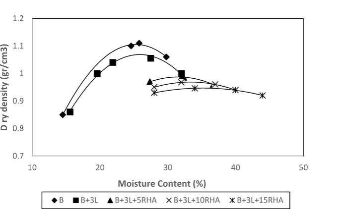
3.1. Effect of RHA on the compaction curves
Effect of rice husk ash on the swelling pressur … 21
Figure 1. Effect of the RHA on compaction curve of soil stabilized with lime
Figure 2. Effect of RHA on compaction curve of the soil stabilized with lime in the presence of sulfate
3.2. Effect of rice husk ash on the swelling pressure of B+3%L
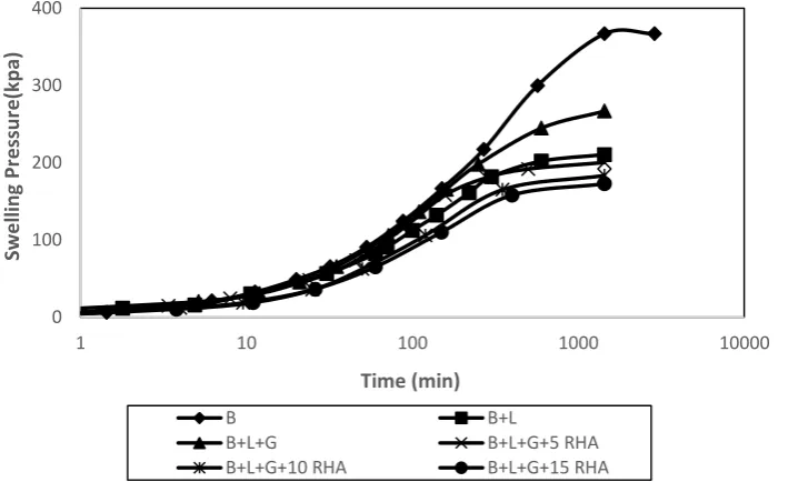
Figure 3 shows the effect of RHA on the swelling pressure of lime-treated bentonite soil tested immediately after mixing and compaction with no curing period. The swelling pressure decreased with an increasing amount of RHA from 210 kPa to 168, 147 and 136 kPa for 5, 10 and 15% RHA, respectively (Table 5). These results mean that the addition of RHA has caused an approximately 20 to 35% decrease in the swelling pressure of lime-treated bentonite soil. This decrease in swelling pressure with no curing period is due to the increase in void ratios (higher optimum water content and lower maximum dry density) caused by the presence of RHA in
0.7 0.8 0.9 1 1.1 1.2
10 20 30 40 50
D
r
y d
e
n
si
ty
(gr
/c
m
3)
Moisture Content (%)
B B+3L B+3L+5RHA B+3L+10RHA B+3L+15RHA
0.7 0.8 0.9 1 1.1 1.2
10 20 30 40 50
D
ry
D
e
n
si
ty
(gr
/c
m
3
)
Moisture CONTENT (%)
samples as well as to a reduced tendency for double layer expansion as the result of the addition of RHA.
Figure 3. The effect of RHA on swelling pressure of soil stabilized with lime measured immediately after mixing
Figure 4 shows the effect of RHA on the swelling pressure of lime-treated bentonite soil after a 7-day curing period. The swelling pressure of lime-treated bentonite soil after 7 days of curing was 150 kPa, which decreased to 100, 82 and 51 kPa for RHA contents of 5, 10, and 15%, respectively (Table 5); a decrease of approximately 33 – 66%. This decrease in swelling pressure of lime-treated bentonite soil was due to the additional cementing effect of chemical products of pozzolanic reactions that occurred between lime and RHA.
Figure 4. The effect of RHA on swelling pressure of soil stabilized with lime after 7 days of curing .
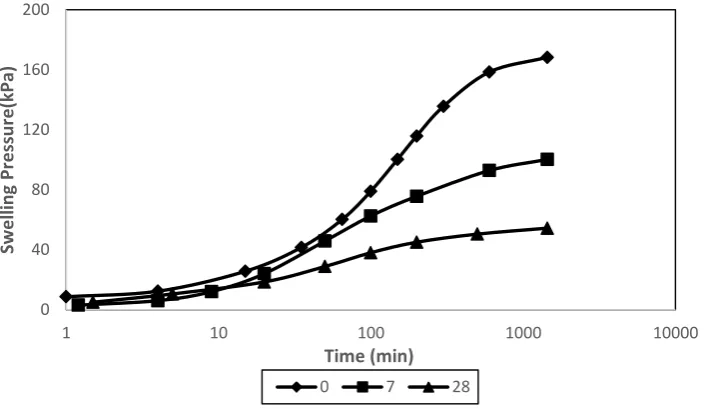
Fig. 5 shows the effect of the curing period on the swelling pressure of B+3%L+ 15%RHA
0 50 100 150 200 250
1 10 100 1000 10000
Swe
lli
n
g
Pr
e
ssur
e
(k
Pa)
Time (min)
B+L B+L+5 RHA B+L+10 RHA B+L+15 RHA
0 20 40 60 80 100 120 140 160
1 10 100 1000 10000
Swe
lli
n
g
Pr
e
ssur
e
(k
Pa)
Time (min)
Effect of rice husk ash on the swelling pressur … 23
samples. A decrease of 63-82% for curing periods of 7 and 28 days was observed compared to samples with no curing period (see also Table 5).
Figure 5. Effect of curing time on swelling pressure of soil stabilized with 3% of lime and 15% of RHA
Table 5 summary of final swelling pressures measured (in kPa)
28days Curing 7days Curing
Uncured Samples
- -
367 B pure
91 149
210 B + 3% L
54 100
168 B + 3% L + 5% RHA
40 82
147 B + 3% L + 10% RHA
25 51
136 B + 3% L + 15% RHA
39 124
267 B + 3% L + 5% G
30 74
200 B + 3% L + 5% G + 5%RHA
18 66
183 B + 3% L + 5% G + 10%RHA
11 57
166 B + 3% L + 5% G + 15%RHA
3.3. EFFECT OF RHA ON THE SWELLING PRESSURE OF B+3%L+5%G
Fig. 6 shows the swelling pressures of B+3%L+5%G without and with RHA at different contents with no curing period. The results indicate that the sample of B+3%L+5%G with no RHA showed a higher swelling pressure than that of sample B+3%L. The higher swelling pressure may be due to the formation of ettringite. However, the addition of RHA to this group of samples caused a decrease in the swelling pressure. The swelling pressures for this group of samples were measured to be 200, 183 and 166 kPa for RHA contents of 5, 10 and 15%, respectively, (see also Table 5) which means a decrease of 25 – 37% compared with the samples with no RHA. The decrease in the swelling pressure in this case may be due to a higher water content and void ratio for these samples as well as a lower tendency for an expansion of the double layer as a result of the presence of RHA. When the values of the swelling pressure for the B+3%L+5%G+RHA samples with no curing are compared with those for the samples of B+3%L+RHA (see Table 5), the effect of both ettringite formation and a reduced void ratio for the former samples may be responsible for the higher values of the former group. According to0 40 80 120 160 200
1 10 100 1000 10000
Swe
lli
n
g
Pr
e
ssur
e
(k
Pa)
Time (min)
Table 5, curing periods of 7 and 28 days caused further decrease in swelling pressure of approximately 40 to 72% for these samples compared with those of the samples without RHA. In this case, a further decrease in the swelling pressure with curing may be due to the cementing effect of additional chemical products generated as a result of pozzolanic reactions that have occurred between the RHA and lime.
Figure 6. Effect of RHA on swelling pressure of lime treated soil in the presence of sulfate with no curing
4. Conclusions
The following conclusions are reached with regard to soil index properties, compaction characteristics and value of constant volume swelling pressure after examinations of different groups of bentonite soil mixtures with 3% of lime + 5% of gypsum and 5, 10 and 15% of rice husk ash.
1. The addition of RHA to soil stabilized with lime lowered the maximum dry density and increased the optimum moisture content.
2. The addition of gypsum to soil stabilized with lime increased the maximum dry density and decreased the optimum moisture content. The addition and increasing the amount of RHA to the stabilized soil with lime and gypsum decreased the maximum dry density and increased the optimum moisture content.
3. The rice husk ash particles that passed through the No. 200 US sieve were more effective in reducing swelling pressure of bentonite than those remaining on the No. 200 US sieve. A more economical procedure for reducing the size of RHA is preleaching with acid before the burning process.
4. Rice husk ash is a suitable additive to reduce the swelling pressure. The addition of RHA to stabilized soil with lime decreased the swelling pressure. The optimal
0 100 200 300 400
1 10 100 1000 10000
Swe
lli
n
g
Pr
e
ssur
e
(k
p
a)
Time (min)
B B+L
Effect of rice husk ash on the swelling pressur … 25
amount for stabilized soil with lime and RHA is to add 15% RHA during 7 days of curing.
5. Rice husk ash is a suitable additive to lower the detrimental effect of sulfate presence in lime-treated expansive soil.
References
1.Slater, D. E. (1983).” Potential Expansive Soils in Arabian Peninsula”, Journal of Geotechnical Engineering, Vol. 109, 5, 744-746.
2.Day, R. W. (1992). “Swell Versusb Saturation for Compacted Clay”, Journal of Geotechnical Engineering, Vol. 118, No. 8, 1272-1278.
3.Osinubi, K. J. (2006). “Influence of Compactive Efforts on Lime-Slag Treated Tropical Black, Clay”, Journal of Materials in Civil Engr. Vol. 18, No. 2, 175-181.
4.Bin, S.; Zhibin, L.; Yi, C.; and Xiaoping, Z. (2007).” Micropore Structure of Aggregates in Treated Soils”, Journal of Material in Civil Engr. Vol. 19. No. 1, 99-104.
5.Peethamparan, S. and Olek, J. (2008). “Study of the Effectiveness of Cement kiln Dust in Stabilizing Na-Montmorillonite Clay “, Journal of Materials in Civil Engr. Vol. 20, No. 2 , 137-146.
6.Madhyannapu, R. S. and Puppala A. J. (2014). “Design and Construction Guidelines for Deep Soil Mixing to Stabilize Expansive Soil”, Journal of Geotechnical and Geoenviron. Engr., Vol. 140, No. 9.
7.Elkady, T.Y.; Al-Mahbashi, A. M.; and Al-Refea, T. O. (2015). “Stress Dependent Soil-Water Characteristic Curves of Lime – Treated Expansive Clay”, Journal of Materials in Civil Engr. Vol. 27, No.3.
8.Thyagaraj, T.; Thomas, S. R.; and Das, A. P. (2017). “ Physico – Chemical Effect on Shinkage Behavior of Compacted Expansive Clay. “ International Journal of Geomechanics, Vol. 17, No. 2.
9.Mitchell. J.K. (1981). “Soil Improvement State of the Art report”. Proc. 10th int. conf. on Soil Mechanics and Foundation Engr. 4,509-565.
10.Mitchell, J. K. (1986). “Practical Problems from Surprising Soil Behavior.” J. of Geotech. Geoenviron. Engng. Division, 112 (3): 259-289.
11.Mitchell, J.K., Dermatas, D. (1992). “Clay Soil Heave Caused by Lime-Sulfate Reactions”. ASTM STP 1135: Innovations and Uses for Lime, Philadelphia, 1992.
12.Petry, T. M., and Little, D. N. (1992). “Update on Sulfate-Induced Heave in Treated Clays: Problematic Sulfate Levels”. In Transportation Research Record 1362, TRB, National Research Council, Washington, DC, 1992, 51.
13.Petry, T. M. (1994). “Studies of Factors Causing and Influencing Localized Heave of Lime Treated Clay Soils (Sulfate Induced Heave)”. U.S. Army Corps of Engineers, Waterways Experiment Station, Vicksburg, MS.
15. Puppala, A. J.; Intharasombat, N. and Vempati, R. K. (2005). “Experimental studies on Ettringite induced heaving in soils “, J. of Geotech. And Geoenviron engng, Vol. 131, Issue 3.
16.Little, D.N., Nair, S.,( 2009). “Recommended Practice for Stabilization for Sulfate Rich Subgrade Soils.” National Highway Cooperative Research Program, Transportation Research Board of the National Academies.
17.Little, D.N.; Nair, S.; and Herbert, B. (2010).” Addressing Sulfate-Induced Heave in Lime Treated Soils.” J. Geotech. Geoenviron. Eng., 2010, 136(1): 110-118.
18.Pakbaz, M.S. and Keshani, A. (2017). “Evaluation of Time rate of swelling pressure development due to the presence of sulfate in clayey soils stabilized with lime”. International Journal of Geomates, Vol. 12, No. 32, 161-165.
19.Rice market monitor. FAO. <http://www.fao.org/economic/est/publications/rice-publications/rice-market-monitor-rmm/en/> FAO (accesed 19.05.14).
20.Mehta, P.K. (1977), “Properties of blended cements, cements made from rice husk ash,” Journal of American Concrete Institute, 74, 440-442.
21.Mehta, P.K. (1979).“The chemistry and technology of cements made from rice husk ash,” Proceedings UNIDO/ESCAP/RCTT Workshop on Rice-Husk Ash Cement, Peshavar, Pakistan, 113-122.
22.Muntohar , A. S. and Hantoro, G.. (2000), “Influence of Rice Husk Ash and Lime on Engineering Properties of a clayee subgrade,” Mhtml:file://A: /Rice Husk Ash and Lime. 23.James and Rao (1986). “Reactivity of Rice Husk Ash”, Cement and Concrete Research,
Vol. 16, 296-302.
24.Real, C.; Alcala, M. D.; and Criado, J. M. (1996). “Preparation of Silica from Rice Husks”, J. Am. Ceram.Soc., 79 (8), 2012-2016.
25.Viet-Thien-An, V., Robler, C.,Danh-Dai, B. and Horst-Michael, L. (2014) , “Rice husk ash as both pozzolanic admixture and internal curing agent in ultra-high performance concrete, ”Cement & Concrete Composites, 53, 270–278.
26.Mesri, G., Pakbaz, M. C. and Cepeda-Diaz, A.F. (1994). “Meaning, Measurement and Field Application of Swelling Pressure of Clay Shales.” Geotechnique, 44(1), 129-145.
27.ASTM. (2010). “Standard Test Methods for Liquid Limit, Plastic Limit, and Plasticity Index of Soils.” ASTM D4318-10e1, West Conshohocken, PA.
28.ASTM. (1996). “Standard Test Methods for One-Dimensional Swell or Settlement Potential of Cohesive Soils.” ASTM D4546-96, West Conshohocken, PA.
Journal of Hydraulic Structures
J. Hydraul. Struct., 2018; 4(2):27-41 DOI: 10.22055/JHS.2018.27848.1093
Characteristic Based Split Finite Element for Unsteady
Dam-Break Problem
Javad Parsa1
Abstract
In this paper, an efficient numerical model for solution of the two-dimensional unsteady dam-break problem is described. The model solves the shallow water equations through Characteristic-Based Split (CBS) finite element method. The formulation of the model is based upon the fractional time step technique primarily used in the finite difference method for the incompressible Navier-Stokes equations. In addition to well-known advantages of the finite element discretization in introducing complex geometries and making accurate results near the boundaries, the CBS utilizes interesting advantages. These include the ability of the method to simulate both compressible and incompressible flows using the same formulation. Improved stability of the CBS algorithm along with its capability to simulate both sub- and super-critical flows are other main advantages of the method. These useful advantages of the algorithm introduce the CBS as a unique procedure to solve fluid dynamics problems under various conditions. Since dam-break problem has principally a high non-linear nature, the model is verified firstly by modeling one-dimensional problems of dam-break and bore formation problems. Furthermore, application of the model to a two-dimensional hypothetical dam-break problem shows the robustness and efficiency of the procedure. Despite the high non-linearity nature of the solved problems, the computational results, compared with the analytical solutions and reported results of other numerical models, indicate the favorable performance of the used procedure in modeling the dam-break problems.
Keywords: Characteristic-Based Split finite element, shallow water, dam-break, bore.
Received: 9 December 2018; Accepted: 25 December 2018
1. Introduction
The computation of unsteady flows is required for the prediction of flood waves in rivers, flows generated by failure of dams and flow conditions in the vicinity of hydraulic structures [1-3]. Numerical models have been introduced as suitable alternatives to other form of flow simulations such as experimental studies [4,5]. Indeed, numerical models have utilized as an essential predictive tool to assess the risks associated with the failure of the hydraulic structures [5,6]. In the recent
1 Water Engineering Department, Faculty of Agriculture, University of Tabriz, Tabriz, Iran,