MicroMate User's Guide
•
MICROMATE USER'S GUIDE
computer: language" in any fO,rm or ,by any
electronlc, mechanlcal, magnetlc, optlcal, chemlcal,
manual or otherwise, without the prior written
permission of Personal Micro Computers, 475 Ellis
Street, Mountain View, California, 94034.
DISCLAIMER
Personal Micro Computers makes no representations or warranties with respect to the contents hereof and specifically disclaims any implied warranties of merchantablility or fitness for any particular purpose. Further, Personal Micro Computers reserves the rignt to revise this publication and ~o make changes from tlme to time in the content hereof without obligation of
Per~opal Micro Computers to notify any person of such reV1Slon or changes.
TRADEMARKS
CP/M is a registered trademark of Digital Research. CP/M PLUS~ DDT, LINK-80, RMAC and SID are trademarks of
Digital Kesearch. T/MAKER is a trademark of Peter
ROlsen. Zilog and Z80 are registered trademarks of Zilog Inc.
DISCLAIMER OF WARRANTY
, No warranties are made with r~spect to the Software utilities provided by Personal Mlcro Computers.
LIMITATION OF LIABILITY
The foregoing warranty is in lieu of all other warranties, expressed or implied, including, but not limited to the lmplied warranties of merchantability and fitness for a particular purpose. In no event will Personal Micro Computers 5e liable for consequential damages even if i t nas been advised of the possibility of such damages.
The MicroMate User's Guide has been prepared using the MicroMate computer and is printed in the United states of Amerlca.
SECTION TWO.
1.2 System Features
1.3 Software Features
1.4 Specifications
INSTALLATION
2.1 Unpacking
2.2 Care and Handling of Diskettes
2.3 Interconnecting
2.4 Power-On Procedure
2.5 Boot Procedure (Loading the Operating System)
2~6 Master Diskette Backup Procedures
2.7 Configuration Procedures
2.8 Power-Off Procedure
2.9 Day-to-Day Power-On/Off Procedures
SECTION THREE. INSTALLING OPTIONAL EQUIPMENT 3.1 Terminal
3.2 Disk Drives
3.3 Parallel Printer 3.4 Serial Printer 3.5 Modern
SECTION FOUR. SOFTWARE UTILITIES
4.1 Format
4.2 Backup
4.3 Config
4.4 Convert
4.5 SysTest
SECTIO~ FIVE. DEVIATIONS FROM STANDARD CP/M PLUS
5.1 Documentation
5.2 Devices
5.3 File Name Differences
5.~ Real Time Clock
APPENDIXES
6.5 Boot Sequence
A. Cables and Connectors
B. Error Messages
C. Problems and Their Probable Causes
2-1 5 1/4 Inch Diskette
2-2 Front Panel
2-3 Rear Panel
2-4 Rear Panel of Qume Terminal
3-1 Diskette Selection for Boot Operation
6-1 Memory Map-First 64K
6-2 Memory Map-Second 64K
6-3 TYPE Byte-Bit Designations
A-l RS-232 Terminal Cable
A-2 RS-232 Modem Cable
A-3 RS-232 Printer Cable
A-4 RS-232 Connector
A-S Parallel Printer Cable
A-6 Disk Drive Cable
A-7 34 Pin Edge Connector
A-8 Interface Connector
2-3 Final Boot Display
4-1 Format utility-Main Menu
4-2 Format utility-Drive Selection 4-3 Format utility-Final Prompt 4-4 Format utility-No Errors
4-5 Format utility-Typical Errors 4-6 FO,rmat utility-Advanced Command 4-7 Backup utility-Source Drive
4-8 Backup utility-Destination Drive 4-9 Backup utility-Verification Mode 4-10 Backup utility-Confirmation Prompt 4-11 Backup utility-Source Diskette Prompt 4-12 Backup utility-Source Diskette Error
4-13 Backup utility-Destination Diskette Prompt 4-14 Backup utility-Destination Diskette Error 4-15 Backup utility-Destination Diskette Error
4-16 Backup utility-Multiple Drive Cylinder Display 4-17 Backup utility-Single Drive Cylinder Display 4-18 Backup utility-Single Drive Error Display 4-19 Backup utility-Wrong Diskette Prompt
4-20 Backup utility-Repeat Prompt
4-21 Backup utility-Confirmation Prompt 4-22 Backup utility-Exit Prompt
4-23 Config utility-Main Menu
4-24 Config utility-Possible Baud Rates 4-25 Config utility-Control Bits Prompt 4-26 Config utility-Word Length Prompt 4-27 Config utility-Stop Bits Prompt 4-28 Config utility-Parity Prompt 4-29 Config utility-Even/Odd Prompt 4-30 Config utility-DTR Prompt
4-31 Config utility-RTS Prompt
4-32 Config utility-Drive Quantity Prompt 4-33 Convert utility-Drive Prompt
4-34 Convert utility-Emulation TYPE Selection 4-35 Convert utility-Conversion Confirmation 4-36 Convert utility-Cancellation Confirmation
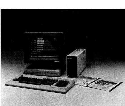
Figure 1-1 MicroMate Computer System
1.1 PHYSICAL DESCRIPTION
/
[image:10.621.91.534.116.491.2]1.2 SYSTEM FEATURES
The MicroMate computer, shipped as a stand alone system, is designed to be used with an asynchronous terminal as a high speed independent work station. It is easy to transport the computer from one work station to another because of its small size.
The MicroMate computer features a Z80-A microprocessor running at 4 Mhz, 128 Kilobytes of Dynamic bank switched RAM, a half-height 5 1/4 inch floppy disk drive with 400 Kilobytes of storage and a Real Time Clock, as well as the CP/M PLUS Operating System.
In addition to the basic configuration, the MicroMate is compatible with a wide range of products as well; for example:
- asynchronous' serial terminals - parallel or serial printers - up to four disk drives
- modems
- asynchronous ser~al peripherals
An internal interface connector offers further expansion capabilities for the MicroMate computer. This connector permits the addition of other peripherals such as hard disk drives, eight-inch disk drives, voice and music synthesizers, and networks.
1.3 SOFTWARE FEATURES
PMC includes three software diskettes with the MicroMate computer. The diskettes are labelled:
"CP/M 3.0 SYSTEM MASTER" "CP/M 3.0 SOURCE MASTER" "T/MAKER MASTER"
Each diskette contains the CP/M PLUS operating system permitting any program on the three diskettes to load and run with a single disk drive system. PMC has implemented the banked version of CP/M PLUS using 128K-bytes of Ram and three types of serial protocol: XON/XOFF, CTS/RTS and DTR/DSR.
The "SYSTEM MASTER" diskette contains programs and Software
utilities used in day-to-day computing. Some of the utilities
included with this diskette are: command help, diskette
formatting, high-speed full diskette copying, drive conversion (which permits reading from and writing to diskettes of other manufacturers), power-on parameter configuration, and system test.
The "SOURCE MASTER" diskette that contains the Bios source code files also has the necessary programs to assemble the source code into a working operating system.
The "T/MAKER" diskette contains all of the files relating to the T/Maker electric spreadsheet and word processing program.
1.4 SPECIFICATIONS
1.4.1 MICROMATE COMPUTER SPECIFICATIONS, Model PMC-101
Processor RAM
ROM
Disk Capacity
Serial Ports Parallel Ports Printer Port Dimensions Weight Power
Z80A, 4Mhz
l28K-bytes, bank switched 4K-bytes, auto boot
One internal drive, 400K-bytes Three optional drives
Two 50 to 19,200 baud, asynchronous 128 bidirectional available
Centronics parallel type
3 1/2 wide x 6 high x 15 inches deep
10 pounds
117 VAC 50/60Hz 75 Watts
1.4.2 QUME TERMINAL SPECIFICATIONS, Model QVT-102
Screen Size Display Format Character Size Attributes Keyboard
Character Set Interface Protocol Baud Rates Dimensions
Weight Power
12 inch non-glare green screen 24 x 80, 25th status/setup line 7 x 9 matrix in a 9 x 12 cell
Blink, blank, underline, reverse, dim Low profile, detached, 85-key QWERTY type
Numeric keypad, function & cursor control
keys, key click and auto repeat 96 ASCII, 32 control, 15 graphic
EIA RS-232-C, Terminal & Aux.
DTR, Xon/Xoff or both 50 to 19,200
Keyboard: 18 wide x 1 1/2 high x 12 inches deep Screen: 13 wide x 14 high x 12 inches deep
Keyboard & Screen Module: 22 pounds
INSTALLATION
2.1 UNPACKING
Your MicroMate system is delivered in two cartons. The smaller carton contains the MicroMate computer, 3 diskettes, and the documentation for the MicroMate, CP/M PLUS, and T/Maker.
The larger carton contains the Qume QVT-102 terminal comprised of an adjustable tilting screen and an 8S-key keyboard, an RS-232 cable, and the Qume manual.
Remove all components and documentation from the cartons and save the cartons and packing material in the event that the MicroMate computer needs to be returned.
If you wish to install your MicroMate system with other than a Qume QVT-102 terminal, please read Section 3 before proceeding.
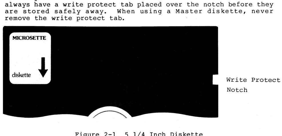
2.2 CARE AND HANDLING OF DISKETTES
Your diskettes (See Figure 2-1) are extremely fragile and sensitive to magnetic fields. Keep them away from your terminal and from metallic objects, such as scissors, screw drivers, speakers etc. Never touch the exposed areas of the magnetic surface. There is a write protect notch in the diskette jacket. When this notch is covered with a Write Protect Tab, the diskette can only be read from and not written to. Master diskettes should always have a write protect tab placed over the notch before they are stored safely away. When using a Master diskette, never remove the write protect tab.
Figure 2-1 S 1/4 Inch Diskette
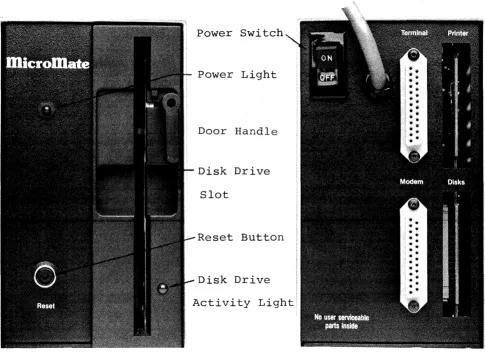
[image:14.612.69.562.491.729.2]Figure 2-2 Front Panel
Power Switch
Power Light
Door Handle
Disk Drive
Slot
Reset Button
Disk Drive
Activity Light
Figure 2-3 Rear Panel
Terminal Connector
[image:15.613.55.540.95.449.2]2.3
1)
2)
INTERCONNECTING
Set the QVT-102 terminal and the MicroMate computer on a very stable and solid work surface. The two pieces must always be a minimum of six (6) inches apart.
Be sure the power switches on the rear of the terminal and the computer are in the OFF position before plugging the terminal and the computer power cords into grounded AC outlets.
It is often convenient to have the computer and all peripherals plugged into an AC power strip so that they can be all turned on or off at the same time.
3) Plug the loose end of the coiled keyboard cable into the matching connector located on the left front corner of the terminal base.
4) Plug either end of the RS-232 cable (round cable) into the connector labelled "EIA" and found on the rear panel of the Qume terminal.
5) Plug the other end of the RS-232 cable into the
connector labelled "TERMINAL" and found on the rear panel of the MicroMate cabinet.
For permanent installation i t is advisable that the lock-down screws on each RS-232 cable connector be screwed into the rear panel mounting studs.
2.4 POWER-ON PROCEDURE
ALWAYS turn on peripheral devices such as the terminal, modern and printer before powering-on the MicroMate computer.
2.4.1 TERMINAL
6) Move the terminal power switch, located on the rear of the base, to the ON position.
7)
8)
9 )
2.4.2
10)
11)
12)
13)
14)
After a short delay, the beeper sounds.
The cursor appears in the upper left corner of the screen while the status line spreads across the bottom of the screen.
If an error message appears or the cursor does not appear, consult your terminal manual.
COMPUTER
Move the MicroMate power switch, located on the rear panel, to the ON position.
The power indicator on the upper left front panel will illuminate.
The drive activity indicator on the front of the A: drive will blink.
Press the RESET button located on the front panel.
If the A: drive activity light does not blink, move the power switch to the OFF position. Repeat from step 10.
2.5
15)
16)
17)
18)
19)
BOOT PROCEDURE (Loading the Operating System)
r
Locate the diskette labelled "CP/M 3.0 SYSTEM MASTER."
V1'~;-fJ~
Remove the diskette from its sleeve, being careful to handle the diskette by the label end only.
Hold the diskette so the label side is facing right and the silver write protect tab is up.
Insert the diskette slowly into the slot in the front
of the A: drive. The diskette must be fully inserted.
Close the drive door by grasping the lower edge of the door lever and in a smooth motion, swing the handle left and up until i t is in a horizontal position.
Clicking noises emanate from the drive. After a short
delay the terminal screen will display the information shown as Screen 2-1, below; after a second delay, the
screen appears as Screen 2-2. The screen will look
like Screen 2-3 after the system boots.
20) The "A> " is called the A> prompt; the" "represents ~
J-the cursor. tY\ )0/1
<-:;
e:,
1
SA~
~ /t-('ff:.
of
( F
I;4l - - - - -b n~~-.r-~
l \ l \ l
CP
1M
V3. 0 leaderCopyright (C) 1982, Digital Research
6lK TPA
CP/M V3.0 Loader
Cbpyright (C) 1982, Digital Research
6lK TPA
l28K PMC-lOl CP/M 3.0 with extended Bios for MicroMate -Vers
3.0-Screen 2-2 Intermediate Boot Display.
CP/M V3.0 Loader
Copyright (C) 1982, Digital Research
6lK TPA
l28K PMC-lOl
A>
CP/M 3.0 with extended Bios for MicroMate -Vers
2.6 MASTER DISKETTE BACKUP PROCEDURES
Please BACKUP your three master diskettes now. It is very important to make backup copies of each original diskette at the time of your first successful installation. The SYSTEM MASTER diskette has two programs, FORMAT and BACKUP, which enable you to prepare new diskettes and BACKUP each of your master diskettes. You will need six blank Double Sided, Double Density diskettes enabling you to make two copies of each master diskette. Follow the steps below very carefully and as soon as you have finished backing up or copying your master diskettes, put the originals in a very safe, cool, dry place.
*
NOTE*
The RETURN key on the Qume terminal is labelled
~
• The ENTER key on the numeric keypad may also be used.2.6.1 FORMATTING
Now that you have signed on by allowing the system to boot, you have the A> prompt on the screen; follow the instructions below for FORMATTING your blank disks:
21) Obtain six blank Double Sided, Double Density 5 1/4 inch diskettes.
22) If the SYSTEM MASTER diskette is not already in the A:
drive, insert i t into the A: drive, and close the door. Type control C (~c) by holding down the key marked Ctrl while simultaneously pressing the key marked
c.
23) After the A> prompt, type in the word FORMAT. Do not leave a space between the A> and FORMAT. Either upper case or lower case letters may be typed. The screen should appear as follows:
A> format
24) Press the RETURN key (..-J). The FORMAT introduction
screen appears.
25) After reading the introduction screen, press the RETURN key to advance to the main menu screen.
26) At the main menu screen, type an F for Format. Press the RETURN key.
27) When the drive selection menu appears on the screen, type an A. Press the RETURN key.
28) The next screen instructs you to insert the Double Sided diskette you wish to format into the A: drive.
Remove the SYSTEM MASTER diskette, replace in sleeve, and insert one of the blank diskettes into the A: drive at this time.
DO NOT press the RETURN key before inserting the blank disk.
The screen first displays the number of each track on side 0, and then on side 1 of the diskette as i t formats. The counting of the tracks changes rapidly on the screen as the drives make a clicking sound.
29) After both sides are formatted, eVery track on both sides is verified for correct formatting. If the format of any track is incorrect, a coded error message appears next to the track number.
30) Opon completion of the formatting and verification
procedure, the screen prompts you to press RETURN.
Before pressing RETURN, check the screen for any errors which appear as a code word bounded by asterisks (**)
next to a track number.
31) Press the RETURN key; the main menu reappears.
32) If any errors are reported, leave the diskette in the A: drive. Try formatting the diskette one more time by repeating from step 26. If errors reappear, remove the diskette, discard it, and skip to step 34.
33) Remove the diskette from the A: drive, replace in sleeve, and set aside.
34) Insert another blank diskette into the A: drive.
35) When the final diskette is prepared for use, remove the diskette, reinsert the SYSTEM MASTER diskette, close the drive door, and type an E at the main menu to exit from the Utility.
2.6.2
The A> prompt should now be visible on your screen.
You are now ready to make BACKUP copies of your master diskettes.
BACKUP
The BACKUP utility is designed to make copies of your master diskettes. It may only be used with a previously formatted diskette.
36) To begin the BACKUP utility, type the word BACKUP at the A> prompt, and press the RETURN key<~).
The BACKUP introduction menu appears on the screen. PLEASE read the directions carefully. The following screens instruct you when to remove or insert the SYSTEM MASTER diskette <called the SOURCE diskette), and when to insert or remove the newly formatted diskette <called the DESTINATION diskette).
In case the introduction screen fails to appear, be sure the SYSTEM MASTER diskette is correctly inserted in the A: drive. Go back to step 36.
37) To advance to the next screen, after reading the
Introduction screen, press the RETURN key.
38) The next screen asks whether or not the data is to be verified. Type a Y. Press the RETURN key.
40) When prompted to load the SOURCE diskette into drive A:, be sure the SYSTEM MASTER diskette is in the A: drive. Press RETURN.
Ten "cylinders" are read from the SOURCE diskette into the computer. The number of each cylinder appears on the screen as i t is being read from the disk. Watch the screen as the numbers are displayed; look for any lower case letters that may appear after a number. If any letters appear after a number, an error has occurred. Note the error and proceed.
41) When prompted to load the DESTINATION diskette into drive A:, remove the SYSTEM MASTER diskette, insert a newly formatted diskette, and close the drive door. Press RETURN.
Ten cylinders are written to the DESTINATION diskette.; The number of each cylinder written appears on the screen. If no letters appear after any of the numbers, the information has been written correctly.
42) Repeat steps 40 and 41 three more times so that all 40
cylinders are copied. Insert the SYSTEM MASTER
diskette when prompted for the SOURCE diskette, and insert the newly formatted diskette when prompted for the DESTINATION diskette.
43) After the last cylinder has been written to the
DESTINATION diskette, the screen asks whether or not to
repeat the backup function. If any errors were
reported in step 40, type Y. Try the BACKUP Utility for this diskette one more time by repeating step 38 through 43.
44) DO NOT answer the prompt until you remove the diskette from the A: drive, and replace it in the envelope.
Prepare a label by writing "CP/M 3.0 SYSTEM" on a self-adhesive label before affixing i t to the first backup diskette.
45) Type Y. Press RETURN, and repeat steps 38 through 44 using another of the newly formatted diskettes for the second backup copy of the SYSTEM MASTER diskette.
47) Type Y. Press RETURN, and repeat steps 38 through 46 using the SOURCE MASTER diskette as the SOURCE diskette instead of the SYSTEM MASTER diskette. Label these backup copies "SOURCE."
48) Type Y. Press RETURN, and repeat steps 38 through 46 using the the T/MAKER MASTER diskette instead of the SOURCE MASTER diskette. Label these backup copies "T/MAKER."
49) Now that you have made two backup copies of all three master diskettes, when the screen prompts whether or not to repeat function, type N. Press RETURN.
When the screen prompts you to "Place SYSTEM disk in A:", insert one of the newly created CP/M 3.0 SYSTEM diskettes into the A: drive, close the door and press RETURN. The A> prompt reappears on your screen.
50) Place your three master diskettes in a very safe, cool, dry place; they will not be needed for any further operations. Use the backup copies just created for all of your day-to-day computer work. The master diskettes should only be used to make new backup copies.
You are now ready to configure the power-on parameters on the CP/M 3.0 SOURCE and T/MAKER diskettes just created.
2.7 CONFIGURATION PROCEDURES
The CONFIG utility is used to change the power-on paramaters on each of the newly created CP/M 3.0 SOURCE and T/MAKER diskettes in order to match the paramaters of the CP/M 3.0 SYSTEM diskette.
51) To begin the CONFIG Utility insert the CP/M 3.0 SYSTEM diskette in the A: drive. Type the word CONFIG after the A> prompt. Press the RETURN key (+--').
The CONFIG introduction menu will appear on the screen.
After reading the introduction screen, press the RETURN key.
The next screen is divided into two parts: the upper portion of the screen displays the current power-on settings; the lower part of the screen is the main menu.
53) The Qume terminal, as shipped from the factory, is set at 9600 Baud. This matches the current setting displayed in the upper portion of your screen.
54) Remove the diskette from the A: drive and replace i t with one of the CP/M 3.0 SOURCE diskettes just created.
55) Select the <W>rite option, by typing a Wand pressing RETURN, to write the current 9600 baud setting to this diskette.
The drive activity light illuminates for a brief period and the main menu reappears.
56) Repeat steps 54 and 55 for the second CP/M 3.0 SOURCE diskette and both of' the T/MAKER diskettes.
You now have 6 bootable diskettes: Two CP/M SYSTEM
diskettes, two CP/M SOURCE diskettes, and two T/MAKER diskettes. Anyone of these diskettes may be used to boot the system when you first turn i t on. Please proceed to the next steps for details on powering off your computer system.
2.8 POWER-OFF PROCEDURE
57) Make sure that you are at the A> prompt.
58) Open the disk drive door.
59) Remove the diskette from the drive and replace i~ in its sleeve.
WARNING
60) Turn OFF all components. There is no required sequence for turning off the computer or peripherals.
You are now ready to use your MicroMate system. PLEASE Read the CP/M PLOS Documentation for details on using CP/M. Some sections of the CP/M PLUS documentation do not apply to the MicroMate PMC-IOI system. Section 5 of this User's Guide lists the inapplicable sections and refers you to an alternate section in this Guide. Read the T/MAKER III REFERENCE MANUAL for details on using T/Maker.
2.9 DAY-TO~DAY POWER-ON/OFF PROCEDURES
Once you have created backup copies of your master diskettes and have configured them for your system, use ONLY the backup copies for your day-to-day computing. The following steps guide you through a normal start up and power down.
2.9.1
1)
2)
3 )
4)
5)
6)
POWER ON AND BOOT PROCEDURE
Refer to Section 2.4.
Use any boot diskette configured for your system.
Hold the diskette so the label side is facing right and the write protect notch is up.
Insert the diskette slowly into the A: drive slot.
Close the drive door.
2.9.2 POWER-OFF PROCEDURE
I)
2 )
3 )
Make sure that you are at the A> prompt.
Open the disk dr i ve door (s).
Re m 0 ve ,t he dis k e t t e ( s) fro m the d r i ve ( s) and rep I ace
it(them) in its(their) sleeve(s).
WARNING
If you leave your diskette(s) in the drive(s) when you power OFF, information on the diskette(s) WILL be ERASED.
INSTALLING OPTIONAL EQUIPMENT
3.1 TERMINAL
For terminals other than the Qume QVT-l02, consult your terminal manual and set the following parameters on your terminal:
110, 300 or 9600 baud rate 8 bi t word length
1 stop bit No parity
Full duplex mode
No protocol (XON/XOFF permissible)
Other terminal parameters should not affect the initial start up procedures.
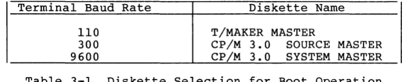
Each of the supplied master diskettes contains the CP/M 3.0 operating system and may be used to boot the system; however, each diskette will boot using a different baud rate.
If your terminal is set for 300 baud, use the CP/M 3.0 SOURCE MASTER diskette; if your terminal is set for 110 baud, use the T/MAKER MASTER; or, if your terminal is set for 9600 baud, use the CP/M 3.0 SYSTEM MASTER diskette to boot the system.
Terminal Baud Rate
110 300 9600
Diskette Name
T/MAKER MASTER
CP/M 3.0 SOURCE MASTER CP/M 3.0 SYSTEM MASTER
Table 3-1 Diskette Selection for Boot Operation
After selecting the proper diskette, follow the procedures in Section 2.5 and make suitable adjustments for use of your own terminal and make the following specific changes:
In step 15, use your selected diskette instead of the SYSTEM MASTER.
Immediately after step 20, insert the SYSTEM MASTER.
remove your selected diskette and Type Control C <~C~
[image:28.613.121.519.463.543.2]In step 53, substitute your terminal settings.
In step 54, i f your selected diskette is the SOURCE diskette, substitute the SYSTEM diskette.
3.2 DISK DRIVES
To connect additional disk drives, use a standard 34
conductor drive expansion cable with a 34 pin edge connector on one end and one, two, or three 34 pin edge connector(s) on the other end. (See Appendix A for a wiring diagram.) Connect the computer end of the cable to the MicroMate's connector labelled "DISKS" and found on the rear panel. Usually the Pin 1 edge of the ribbon cable is marked by a different or darker color. When plugged in, Pin I of the connector must be down, and the cable often exits from the left side of the connector. If you are not sure about the exact location of Pin I on your cable, consult your dealer. If the add-on disk drives are located on the right side of the computer as viewed from the front, the other connector(s) plug into the drive(s) and should not have any twists in the cable.
IMPORTANT
a) Every add-on drive must be properly configured prior to use. Refer to your disk drive manual for this procedure.
b) When adding one disk drive, set the add-on drive select jumper or switch to DS2; when adding two disk drives, set the second add-on drive select jumper or switch to DS3; and when adding three disk drives, set the third add-on drive select
jumper or switch to DS4.
c) The user is also responsible for removing the termination resistor pack or jumpers from all
add-on drives. The MicroMate's built-in drive is
already terminated.
3.3 PARALLEL PRINTER
To connect a Centronics type parallel printer, use a 34 conductor ribbon cable with a Centronics D-connector on one end and a 34 pin edge connector on the other (available from PMC as Part No.: Cab-a5). Plug the edge connector end of the printer cable into the MicroMate's connector labelled "PRINTER" and found on the rear panel. Usually the Pin 1 edge of the ribbon cable is marked by a different or darker color. When plugged in, Pin 1 of the connector must be down, and the cable often exits from the left side of the connector. If you are not sure about the exact location of Pin 1 on your cable, consult your dealer. The printer end of the cable is a standard Centronics connector. Consult your printer manual for proper connection. (See Appendix A for a wiring diagram of a standard Centronics printer cable.)
3.4 SERIAL PRINTER
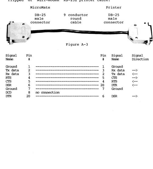
To connect a serial type printer, generally, you use a "flipped" or "Null-Modem" Asynchronous Serial RS-232 cable with male connectors on both ends. Plug one end of the cable into the connector of the MicroMate labelled "MODEM" and found on the rear panel. The other end of the cable connects to your ser ial printer. Consult your printer manual for instructions on the connecting and wiring of the DB-25 connector. (See Appendix A for a w ir ing diagram of a IIf lipped" RS-23 2 pr inter cable.)
Use the DEVICE utility to set the logical LST: device to MODEM and change the baud rate temporarily. (See the CP/M User's Guide.) As shipped from the factory, the MicroMate's MODEM port is set to 300 baud. The CONFIG utility may be used to change the power-on MODEM baud rate setting. (See Section 4.3.)
3.5 MODEM
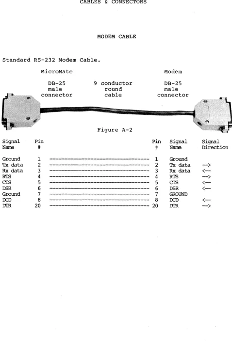
To connect a modem, use a standard Asynchronous Serial RS-232 modem cable with male connectors on both ends. Plug one end of the cable into the lower right connector labelled "MODEM" on the rear panel of the MicroMate. The other end of the cable connects to your modem. Consult your modem manual for further installation instructions. (See Appendix A for a wiring diagram of a standard RS-232 modem cable.)
SOFTWARE UTILITIES
The SYSTEM MASTER diskette supplied by PMC contains five useful Software utilities: FORMAT, COPY, CONVERT, CONFIG, and SYSTEST.
Each Software Utility first displays an introductory screen that explains the procedure. After you read the information presented, press the RETURN key to advance to the screen containing the main menu. The subsequent screens guide you step by step through the Utility by using complete menus, messages, and error trapping.
Each Utility is designed to provide you with the capability of being able to abort (cancel) while the Utility is running. If you need to abort the utility, type Control C by holding the
Ctr1 key down and simultaneously pressing the C key.
4.1 FORMAT UTILITY
Command Syntax: FORMAT
The process called "formatting a diskette" prepares a diskette to receive information by creating tracks and sectors. Each computer system formats diskettes for use on that particular system. The PMC FORMAT utility provides a method to prepare
diskettes for use with the MicroMate system. This utility
allows you to format TYPE A (See Section 4.4) Double Sided, Double Density (DSDD) and TYPE B Single Sided, Double Density (SSDD) diskettes and verify the transferred sector map. It may also be used to erase completely and reformat a diskette needing correction of any hard errors that have developed.
4.1.1 NORMAL OPERATION
The main menu of the FORMAT Utility offers three options: <F>ORMAT a diskette, <V>ERIFY the integrity of a previously
formatted diskette, or <E>XIT from the utility to CP/M. Select
FORMAT or VERIFY by typing an F or V and pressing the RETURN key.
Your choice:
<F>ormat <V>erify
<E>xi t to CP
1M
(All data will be erased)
(No data will be erased)
(Do not enter the <> brackets)
Screen 4-1 Format Utility-Main Menu
While listing the possible drive choices, the next screen prompt requests the letter of a drive. Type the letter for the
chosen drive and press the RETURN key. The screen prompt will be
re-displayed if an invalid drive letter is entered, so that you may correct the entry.
<F>ormat <V>erify
<E>xi t to CP
1M
(All data will be erased)
(No data will be erased)
(Do not enter the <> brackets)
Your choice:F
Enter dr i ve to use: <A> , ••••
After a valid drive letter is entered, the screen prompts you to insert either a Single or Double Sided diskette into the corresponding drive. If the drive is TYPE A, both sides of the diskette will be formatted and/or verified; if the drive is TYPE B, only one side of the diskette will be used; or, if the drive TYPE is other than A or B, i t cannot be formatted nor will its letter be displayed. (See Section 4.4 on the CONVERT utility for further explanation of TYPEs.)
Pressing the RETURN key starts the FORMATTING or VERIFYing procedure. DO NOT press RETURN until the proper diskette has been inserted into the selected drive.
Insert DOUBLE sided diskette to FORMAT into drive A and Press <RETURN> to continue or control C <AC> to abort.
Screen 4-3 Format Utility-Final Prompt
The TRACK NUMBER and the current SIDE being formatted and/or verified is displayed on the screen while the Utility is running. As soon as the formatting is completed, the verify mode is entered automatically.
Formatting: Track Side 0
39
Track Side 1 39
Verifying: Track Side 0
39
Track Side 1 39
Sometimes during the FORMAT procedure, a new diskette
formats incorrectly. When this happens, an error message
bounded by asterisks appears on the screen next to the number of the track causing the error. If, after trying to reformat the diskette one more time, the error s t i l l appears, then discard the unusable diskette. Only two possible errors can occur during formatting. They are * WRITE PROTECT * and * WRITE FAULT *. You may recover, however, from a
*
WRITE PROTECT * error. wait for all drive activity to cease, remove the write protect tab from the diskette, and try again.Formatting: Track Side 0
10 **~~ITE FAULT**
39
Track Side 1
39
Verifying: Tr.:ack Side 0
10 **RECORD IDr FDUND**
39
Track Side 1
39
Press <RETmu~> to continue or control C <~C> to abort.
Screen 4-5 Format Utility-Typical Errors
4.1.2 ADVANCED OPERATION
The advanced command form, which can be used only for formatting, requires prior selection of the drive to be used. The only prompt displayed is a prompt requesting the insertion of the proper diskette into the selected drive. If the drive specified is an invalid drive or type, then normal prompts will be displayed, and you will be requested to enter a valid drive letter.
Command syntax: FORMAT,drive
A>FORMAT,B
Insert DOUBLE sided diskette to FORMAT into drive B and Press <RETURN> to continue or control C <AC> to abort.
Screen 4-6 Format Utility-Advanced Command
4.2 BACKUP UTILITY
Command Syntax: BACKUP
*
NOTE*
SOURCE is the drive or diskette being copied FROM. DESTINATION is the drive or diskette being copied TO.
This Software Utility creates an exact copy of a MicroMate TYPE A diskette. By means of its own mini-operating system, the BACKUP Utility is able to copy a diskette using only one disk drive. One advantage of the MicroMate's 128 Kilobytes of RAM is that ten cylinders (twenty tracks) can be read at one time from the SOURCE diskette and can be held in this memory until the DESTINATION diskette is ready to receive the transferred information. This procedure need only be repeated three more times until all the cylinders have been read and written.
When used with multiple drives~ however, this utility copies the diskette by a faster technique of transferring data one cylinder at a time. One important feature of the Utility comes into play whenever a SOURCE diskette is inserted by mistake, instead of a DESTINATION diskette. The Utility marks the DESTINATION diskette on single drive systems; therefore, inserting the wrong diskette causes an error message to appear. This BACKUP Utility may be used only with TYPE A drives (See Section 4.4 on the CONVERT Utility for further information on TYPEs.)
When the BACKUP Utility f i r s t begins to run, an
Enter the letter of the DRIVE to use as
SOURCE DRIVE
Do not enter the <> brackets.
Your choice <A>, <B>, ..•.
Screen 4-7 Backup utility-Source Drive
Enter the letter of the DRIVE to use as
DESTINATION DRIVE
Do not enter the <> brackets.
Your choice <A>, <B>, ..••
Screen 4-8 Backup utility-Destination Drive
The next screen asks you to decide about verification. Verification means that after the data is written to the DESTINATION diskette, i t is read back from the DESTINATION
di~kette, and then i t is compared to the original data read from the SOURCE diskette. (If they do not match, a lower case "v" error code is displayed on the screen after the cylinder number.) It is strongly suggested that you always answer the verification
question with Y (yes). Although the backup takes slightly
Do you wish to VERIFY DATA as written?
<Y)es, <N)o or <~C) to exit.
Screen 4-9 Backup utility-Verification Mode
Next the screen displays a prompt reaffirming the selection of the drives being used in the BACKUP function. Type a Y and Press the RETURN key if you are satisfied with the drive selection.
The Backup will be FROM A: TO A:
Do you wish to proceed with Backup?
<y>es, <N>O or <"'C) to exit.
Screen 4-10 Backup utility-Confirmation Prompt
Load SOURCE DISK into A:
Press <RETURN) to continue or control C <~C) to exit.
If the source diskette is formatted, an error screen appears. SOURCE dr i ve, insert the proper RETURN. If you type an N and press the verify prompt (Screen 4-9.)
not a TYPE A diskette or Remove the diskette from the diskette, type Y and press RETURN, you are taken back to
Unable to verify SOURCE disk as Double Density, Double Sided
Do you wish to try again?
<y>es, <N>O or
< ....
C> to exit.Screen 4-12 Backup Utility-Source Diskette Error
The next screen prompts you to insert the DESTINATION diskette into the selected DESTINATION drive. The activity light on the selected drive blinks as a helpful reminder. Insert your DESTINATION diskette into the drive, and make sure you have inserted the proper diskette before pressing RETURN.
Load DESTINATION DISK into A:
Press <RETURN> to continue or control C
< ....
C> to exit.When the DESTINATION diskette is first inserted, the utility automatically checks the diskette for previous formatting and whether or not the diskette contains any information. If your DESTINATION diskette has not been formatted already, an error message appears.
Unable to verify DESTINATION disk as Double Density, Double Sided
Do you wish to try again?
<Y>es, <N>O or <~C> to exit.
Screen 4-14 Backup Utility-Destination Diskette Error
You may retry with another diskette or type control C to exit to CP/M (Hold the Ctrlkey while simultaneously pressing the C key), format the diskette using the FORMAT Utility, and then re-run BACKUP.
If the DESTINATION diskette contains programs or data, the following message appears:
The DESTINATION Disk is not Blank
OOI'E: ALL DATA NOO ON THE DESTINATION DISK WILL BE
wS'r
IF YOU PROCEED!Do you wish to proceed with Backup?
<Y>es, <N>o or <~C> to exit.
If the DESTINATION diskette contains data or programs and you are positive that you no longer need to keep any of the information currently on the DESTINATION diskette, then type a Y. Press the RETURN key and continue on to the next step.
When u3ing multiple drives, each cylinder number is displayed as i t is transferred from the SOURCE diskette to the
DESTINATION diskette. A total of 40 cylinder numbers will be
displayed using the numbers 0 through 39.
Backup Function underway
Symbols are:
Numbers - Correspond to Track Numbers
w - Correspond to Hard Write Errors
r - Cbrrespond to Hard Read Errors
v - Correspond to Hard Verify Errors
0 1 2 3 4 5 6 7 8 9
10 11 12 13 14 15 16 17 18 19
20 21 22 23 24 25 26 27 28 29
30 31 32 33 34 35 36 37 38 39
Screen 4-16 Backup utility-Multiple Drive Cylinder Display
When you use a single drive, each cylinder number is
displayed as the cylinder is read. A total of 10 cylinders will
be read from the diskette at one time. The screen next prompts
you to remove the SOURCE diskette and to insert the DESTINA'rION
diskette. The ten cylinders just read into memory are then
written to the DESTINATION diskette. You are again prompted to
re-insert the SOURCE diskette. ThL3 process is repeated only 3
more times in order to copy an entire diskette.
Backup Function underway
Symbols are:
o
1Numbers - Correspond to Track Numbers
w - Correspond to Hard Write Errors
r - Correspond to Hard Read Errors
v - Correspond to Hard Verify Errors
2 3 4 5 6 7 8 9
If any errors occur dur ing the BACKUP procedure for ei ther single or multiple drives, they are displayed as lower case letters after the cylinder number. Refer to the error code table displayed above the numbers for the error type.
*
NOTE*
Single drive users should pay close attention to the screen while the cylinder numbers are being displayed because the numbers and the error codes will scroll off
the screen after every 10 cylinders have been
transferred.
Backup Function underway
Symbols are:
o
1Numbers - Correspond to Track Numbers w - Correspond to Hard write Errors r - Correspond to Hard Read Errors v - Correspond to Hard Verify Errors
2v 3 4 5 6 7 8 9
Screen 4-18 Backup Utility-Single Drive Error Display
On single drive systems, the DESTINATION diskette is especially marked by the Utility so that if the SOURCE diskette
THIS IS NOT THE CORRECT DESTINATION DISK
Please check the Disk
wad DEsrINATION Disk into A:
Press <RETURN> to continue or control C <AC> to exit.
Screen 4-19 Backup Utility-Wrong Diskette Prompt
When the BACKUP is completed, you are asked whether the BACKUP function is to be repeated using the same drive{s) as previously specified; the SOURCE and DESTINATION diskettes may be the same as before or different.
30 31 32 33 34 35 36 37 38 39
Do you wish to repeat the Backup function?
<Y>es, <N>o or <AC> to exit.
If you want to make another BACKUP, type a Y for yes. Press the RETURN key, and you will return to the prompt which reaffirms the selected drive.
The Backup will be FRCM A: TO A:
IX> you wish to proceed with Backup?
<Y)es, <N>O or <"'C) to exit.
Screen 4-21 Backup Utility-Confirmation Prompt
Now you may insert new SOURCE and DESTINATION diskettes or use the same SOURCE diskette and a new DESTINATION diskette.
If you do not want to make another backup, type an N, and press the RETURN key. The following prompt is displayed:
Place SYSTEM disk in A:
Press <RETURN) to exit to CP/M.
Screen 4-22 Backup utility-Exit Prompt
4.3 CONFIG UTILITY
Command Syntax: CONFIG
PMC has included this Software utility with the MicroMate computer to allow for the maximum amount of peripheral flexibility. For normal installations the Utility will be needed only once. Users who change their peripherals often or who move their computer from one work station to another may want to use i t more often.
The CONFIG Utility permits modification of the power-on parameters stored on a SYSTEM diskette. Only the A: drive may be used to read the parameters from or write the parameters to the diskette.
The parameters are never changed by doing a COPYSYS: they are merely copied from one diskette to another along with the CP/M Loader and, optionally, CPM3.SYS (refer to the CP/M User's Guide for further information on COPYSYS.)
NEVER change the parameters on your MASTER diskettes, as the individual baud rates of each diskette may be needed to power-on with a another terminal.
The three groups of parameters are: terminal, modem and drive. The terminal and modem groups each consist of the following parameters: Baud Rate, Word length, Stop Bits, Parity, and the state of the DTR and RTS protocol lines. The drive group consists of a single parameter: Drive quantity.
The values of the power-on parameters are used for the above groups of parameters when the computer is first turned on.
When the Utility is first run, an appears. It prompts the user to insert parameters are to be read into the A: drive.
introductory screen the diskette whose
Press RETURN.
The parameters are read from the diskette in drive A: and then the main menu, which is divided into two portions, is displayed. The upper portion of the screen displays the current settings of the power-on parameters: the lower portion of the screen offers choices for changing the parameters of the terminal or modem or for changing the quantity of the disk drives attached
to the MicroMate. Other menu options include writing the
See Section 5.2.1 for the default power-on parameter values as shipped from the factory.
Current settings:
Terminal: 9600 Baud, 8 Bit Word, 1 Stop Bits, No Parity, 1JI'R on, RTS off
Modem: 300 Baud, 8 Bit Word, 1 Stop Bits, No Parity, 1JI'R on, RTS off
Drive Qty.: 1
Set power-on parameters for:
or
<T>erminal <M>odem
<D>isk Drive Quantity
<W>rite new parameters to drive A <E>xi t to CP
1M
Enter your choice ?
Screen 4-23 Config utility-Main Menu
4.3.1 TERMINAL & MODEM GROUP
In order for the terminal or modem to "talk" to the computer, the baud rate, word length, stop bits, and parity must be exactly the same for each device. If the terminal parameters do not match those of the MicroMate, the terminal will display "garbage" (sequences of characters and symbols that make no sense) or, because the MicroMate can not understand the data being entered, i t may display nothing at all.
If you are unable to determine the values that your terminal uses for Word Length, Stop Bi ts, Par i ty, DTR and RTS, i t is best to leave them at the factory settings. Many terminals, modems and printers work at these settings.
Typing a T or an M ( for Terminal or Modem) followed by pressing the RETURN key causes the screen to display a table of the different baud rates that the operating system can support. Type the letter found in the left column that corresponds to the
baud rate desired. Press RETURN.
<A> 50
<B> 75
<C> 110
<D> 134.5
<E> 150
<F> 300
<G> 600
<H> 1200
<I> 1800
<J> 2400
<K>
3600<L> 4800
01> 7200
<N> 9600
<0> 19,200
Your Choice ?
Screen 4-24 Config Utility-Possible Baud Rates
The next screen permits changing the control bits. Unless
you are sure of the settings of ALL the control bits, answer by
typing an N. After pressing RETURN, the Main Menu reappears; the new baud rate chosen will now be displayed in the current settings table for the device first selected.
Do you wish to change the Control Bits?
Control bits are:
Word Length Stop Bits
Parity Request To Send Data Terminal Ready
<Y>es or <N>o
Should a Y be typed and the RETURN key pressed at the "control bits" menu, the prompt will request the word length. The possible values are displayed on the screen. Enter the selected number and press RETURN. The normal setting is 8.
Word Length <8>, <7>, <6> or <5> ?
Screen 4-26 Config utility-Word Length Prompt
The next prompt asks for the number of stop bits; the choices are displayed on the screen. Again, choose a number, enter your selection, and press RETURN. The normal setting is 1.
WOrd Length <8>, <7>, <6> or <5> ? Stop Bits <1> or <2> ?
Screen 4-27 Config Utility-Stop Bits Prompt
Now the prompt on the screen asks whether parity is to be enabled or disabled. The normal setting is <D>isable. Type a D and press RETURN. Should you want Parity enabled, type E instead of D.
WOrd Length <8>, <7>, <6> or <5> ? Stop Bits <1> or <2> ?
(E>nable or <D>isable Parity ?
If E is your response, the prompt asks you if parity is to be <E>ven or <O>dd. Type E or 0 followed by RETURN.
WOrd Length <8>, <7>, <6> or <5> ? Stop Bits <1> or <2> ?
<E>nable or <D>isable Parity ? <E>ven or <O>dd parity ?
Screen 4-29 Config Utility-Even/Odd Prompt
If a D is entered, the question about Even and Odd is not presented.
The last two prompts question whether DTR and RTS are to be On (High) or Off (Low). Answer with the number that corresponds to the state desired. Press RETURN. The main menu reappears after answering all the prompts; the selected new settings are displayed at the top of the screen under the heading, Current Settings.
Word Length <8>, <7>, <6> or <5> ? Stop Bits <1> or <2> ?
<E>nable or <D>isable Parity? DTR <O>=off or <l>=on?
Screen 4-30 Config Utility-DTR Prompt
WOrd Length <8>, <7>, <6> or <5> ? Stop Bits <1> or <2> ?
<E>nable or <D>isable Parity ?
DTR <O>=off or <l>=on? RTS <O>=off or <l>=on?
4.3.2 DRIVE GROUP
The single parameter drive quantity, used by the operating system, determines the number of disk drives attached to the
MicroMate computer. Changing this parameter is necessary
whenever disk drives are added to or subtracted from the MicroMate system; otherwise, the operating system may "hang" if i t tries to access a non-existent drive. When setting this parameter, ALWAYS include the built-in drive in your count. The minimum value is 1; the maximum value is 4.
From the Main Menu choose <D>rive Quantity, type a D, and then press the RETURN key. The Drive Quantity Menu appears. The choices are 1-4. Type the number of drives desired; be sure, however, to add the built-in drive A: as number 1.
Disk Drive Quantity Selection
Enter Quantity of Disk Drives available for system use.
Include built in drive.
Min~um value is <1> Max~um value is <4>
Quantity?
4.3.3 OTHER MENU OPTIONS
In order to save these new settings onto the diskette, the <W>rite option MUST be used. Type a Wand press RETURN to write the new parameters to the diskette. DO NOT type an E to <E)xit from the CONFIG Utility before writing the new settings, unless you want to abort.
Even if the new parameters are written back onto the diskette before discovering an error, i t is possible to return, correct the parameter settings, and rewrite the parameters onto the diskette again.
The new parameters will not take effect until: 1) they are
written to the diskette, and 2) the front panel reset button is
4.4 CONVERT UTILITY
Command Syntax: CONVERT
Unfortunately there is no standard method used to store information on a 5 1/4 inch diskette. Some computer manufacturers use Single Sided, Single Density (SSSD), while others use Single
Sided, Double Density (SSDD), Double Sided, Single Density
(DSSD), or Double Sided, Double Density (DSDD) 5 1/4 inch diskette storage techniques.
PMC includes a CONVERT Utility that will permit users to "emulate" several of the different storage techniques that other manufacturers use.
Anyon-line drive may be converted to a different type. Once a drive is converted, you may read and write to the other diskette type; however, the diskette must have been previously formatted by the machine whose type is being emulated. The MicroMate's FORMAT Utility is not capable of formatting any TYPEs other than PMC-IOl TYPE A and B.
The popular brand name TYPEs that can be converted are found on the emulation TYPE screen. The actual conversion of the drive occurs after the TYPE selection has been entered and remains effective until you press the RESET button or until you perform a new drive conversion on the same drive.
4.4.1 NORMAL OPERATION
The first screen displayed, after you type CONVERT, provides a brief introduction. Press the Return key to continue. The next screen to appear is the dr ive selection display that presents the drive letters available for conversion.
Enter the letter of the Drive to be used.
do not enter the
<>
brackets.Your choice if <A>, •••••••
If you press the RETURN key without entering a drive letter, the Utility aborts! Once the proper drive is selected,
the Emulation TYPE Screen appears. The "current setting" is
listed on the screen first and is followed by the l i s t of
possible emulations. Select the desired emulation TYPE to finish
the conversion process.
Drive A is currently set to Type A
TYPE COMPUI'ER
<A> PMC-IOI <B> PMC-IOI <C> Omikro~n~ ___
SIDES DENSITY
2 Double
2 Double
I S~' _ _ _ _ _
TYPE COMPUrER
<N> MicroDecision <0> MicroDecision
<z>
Select NEW Type for drive A to emulate, <A> thru <Z> or <AC> to abort:
Screen 4-34 Convert Utility-Emulation TYPE Selection
Once the selection has been made, a confirming prompt is displayed on the screen.
Drive A is now set to Type A
A>
If you abort the Utility or enter a non-existent TYPE letter, a different prompt is displayed, which indicates that no changes were made.
Utility aborted, NOTHING done.
A>
Screen 4-36 Convert utility-Cancellation Confirmation
4.4.2 ADVANCED OPERATION
The advanced command form requires that the user know which drive is to be converted to which type. No prompts will be displayed except for a prompt confirming that the conversion has taken place.
Command Syntax: CONVERT, drive ,type
A>CONVERT,C,B
Drive C is now set to Type B
A>
If the drive specified is an invalid drive or the TYPE letter is out of range, normal prompts are displayed at the point of error and you are prompted to enter a valid response. If the TYPE letter is not valid the utility aborts.
Utili ty aborted, NarHING done.
A>
Screen 4-38 Convert utility-Cancellation Confirmation, Advanced
*
NOTE*
4.5 SYSTEST
Command Syntax: SYSTEST
Before this Software utility can be used, a special SYSTEST diskette must be made. Use the BACKUP utility to copy a SYSTEM
diskette. Label the copy diskette SYSTEM TEST. From this
diskette, erase the two files HELP.COM and,HELP.HLP to obtain needed working room. Using ED (see CP/M User's Guide), create a file called PROFILE.SUB that contains the single word SYSTEST, followed by a carriage return, and a line feed.
To test the integrity of the hardware, disconnect the terminal end of the RS-232 cable from the terminal and plug i t into the connector labelled "MODEM" on the rear panel of the MicroMate. If this step is skipped, all tests except for the DART test, will be performed.
Insert the special SYSTEM TEST diskette into the A: drive and press the reset button. This initiates a continuously running loop that will keep the drive activity light blinking until an error occurs.
The disk drive, serial ports, all l28K bytes of memory, and all major IC chips are tested.
If a parallel printer is attached, the name of each segment of the test, as i t begins, is printed. The tests function as normal even if no printer is attached; however, i t is difficult to tell which test, if any, fails. There are four tests: Disk, Seek, Dart, and RAM.
Disk test: Seek test: Dart test: RA1\1 test:
checks the read/write capabilities of the drive. checks the stepping capability of the drive. checks the operation of the serial ports. test all 128K bytes of memory.
This is not a diagnostics test, but a functionality test. If an error occurs during any test, an error message is printed out next to the identified test.
....
DEVIATIONS FROM CP/M PLUS DOCUMENTATION
5.1 DOCUMENTATION
CP/M
User's Guide
MicroMate User's Guide
1.1 1.4
3.3.1 3.5
5.COPYSYS 5.DEVICE
CP/M
Programmer's Guide
Read Section 2 instead.
BACKUP is a faster and easier method. See Section 4.2.
Ignore non-banked sections.
The DEVICE command and Logical devices are supported. See Section 5.2.
COPYSYS can only be used with TYPE A drives. See Section 5.2 for physical devices.
See Section 5.5 regarding Protocols.
MicroMate User's Guide
Ignore non-banked sections. 1.1
1.5
1.6.1
See Section 6.1 for memory maps.
The CCP is stored on the system cylinder. See Section 6.4.
See Section 6.5 for Cold Start Operation.
* NOTE *
CP/M System Guide
MicroMate User's Guide
Ignore non-banked sections.
1.5 See Section 6.1 for memory maps.
1.9 The MicroMate uses a ROM loader. Refer to
Section 6.5.
2.5 2.6
2:7
3.4
4.1
4.7.3
5.1 5.2
Apndx.A Apndx.B Apndx.E-J
MULTIO is not implemented. XMOVE is implemented.
Clock is supported. See Section 5.4.
FLUSH is not implemented.
Refer to Section 5.3 for f i l e name
differences.
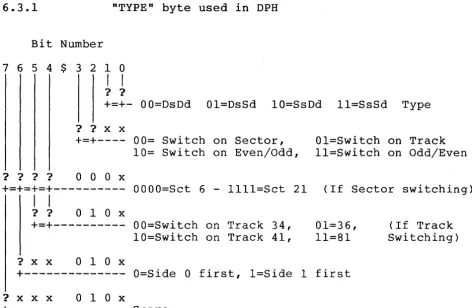
TYPE is used. See Section 6.3.
Type the GENCPM.DAT file for default values. The CCP is stored on the system cylinder. See Section 6.4
Media flag not implemented. Ignore.
Ignore (See the source code files)
*
NOTE*
,,<,
5.2 DEVICES
Under CP/M 3.0, Logical devices are implemented for the following physical devices;
TERMNL -Serial communication to a terminal (TERMINAL connector)
MODEM -Serial communication to a modem (MODEM connector)
CENTRN -Parallel communication to a printer (PRINTER connector)
5.2.1 DEFAULT POWER-ON PARAMETERS
Baud Word Stop Parity DTR RTS
Rate Length Bits
SYSTEM MASTER diskette
Terminal 9600 8 1 Disabled On On
Modem 300 8 1 Disabled On On
Drive Qty. 1
SOURCE MASTER diskette
Terminal 300 8 1 Disabled On On
Modem 300 8 1 Disabled On On
Drive Qty. 1
T/MAKER diskette
Terminal 110 8 1 Disabled On On
Modem 300 8 1 Disabled On On
Drive Qty. 1
QUME QVT-l02 Terminal
Terminal 9600 8 1 Disabled On On
Modem 9600 8 1 Disabled On On
5.3 FILE NAME DIFFERENCES
BIOSKRNL .. ASM CHARIO.ASM MOVE.ASM BOOT.ASM DRVTBL.ASM FDl797SD.ASM PORTS.LIB MODEBAUD.LIB CPM3.LIB
5.4 REAL TIME CLOCK
integrated into BIOS3.ASM integrated into BIOS3.ASM integrated into BIOS3.ASM integrated into BIOS3.ASM integrated into BIOS3.ASM DISKIO.ASM PORTS.LIB MODEBAUD.LIB CPM3.LIB PMCEQU.LIB LDRBIOS.ASM
The Real Time Clock is implemented using the Zilog CTC chip
and is interrupt driven. Therefore, operations involving
considerable disk accesses cause the clock to lose time.
5.5 PROTOCOLS
XON/XOFF protocol is supported and can easily be turned ON or OFF by using the DEVICE Utility (see your CP/M User's guide.)
The Bios can support DTR and/or RTS protocol. Neither protocol is implemented at the time of shipment. The protocols cannot be implemented via any utility. In order to implement one, the other or both, a single word must be changed in the MicroMate equate file and the Bios reassembled.
On the SOURCE diskette at the top of the PMCEQU.LIB file are two equates:
DTR RTS equ equ false false
Using ED (see CP/M User's Guide) change the word "false" to "true" for the protocol(s) you wish to implement.
e.g.: to implement DTR protocol only, the two equate lines should read:
DTR RTS equ equ true false
Save the new PMCEQU.LIB back to disk and exit ED.
The new Bios must now be reassembled. To make life simple, PMC has provided a submit file to do this. At the A) prompt type
SUBMIT BIOS and then press RETURN. The submit file will reassemble the Bios and link i t to the operating system files to create a file called CPM3.SYS. Before the new protocol(s) can take effect the system must be booted from the diskette that contains this new version of CPM3.SYS. Make sure you run COPYSYS (see CP/M User's Guide) to transfer the Boot Loader to the boot cylinder.
Once implemented, the only way to disable the protocol(s) is to change the equate(s) back to false and reassemble the Bios OR re-boot the system using a diskette that has a non DTR and/or RTS protocol version of CPM3.SYS.
TECHNICAL REFERENCE
6.1 BANK SWITCHING
Bank switching is done by the operating system and is transparent to the users' programs. Individual programs MAY NOT perform bank switching, as all banked