SECTION 1: SPECIFICATIONS
1. 0 GENERAL
The DCE is a multifunction VME bus interface board that consists of two separate controllers. One controller is a standard 712. The other controller is a Xylogics Model 732 Disk Controller that couples two floppy disk drives and one QIC02 tape drive to VMEbusl systems.
1.1 USING THIS MANUAL
This manual describes the 732 floppy/QIC02 controller.
Section 2 describes how to install and test the 732; Section 3 describes the 732 registers; Section 4 describes the
lOPBs; and Section 5 describes the 732 commands. Section 6 describes error processing; Section 7 is a programming
tutorial; Section 8 explains the 732's special functions; Section 9 describes the 732 theory of operation; and Section 10 includes maintenance aides.
1.1.1 Abbreviations
This manual uses the following mnemonics: AIO AlOP AlOR AM ASR AUD BHT CHEN CMPL CRIO eRBS CTYP DFLT DMA DRDY
Add New IOPB AIO Pending
AIO Response Time Address Modifier Automatic Seek Retry Auto-update
Black Hole Transfer Chain Enable
Command Complete Clear Remove IOPB Clear Register Busy Controller Type Drive Fault
Direct Memory Access Drive Ready
1. VMEbus is a trademark of the VMEbus International Trade Association.
1.1.1 Abbreviations (continued) EDT ERRS FERR FIFO H ICS lEC IOPB MBS MMA MM NPRM OVS PNUM PRlO PSEL RBS REGCEL RIO RMM ROR SGM SKER TDT THRO TMOD VMEDMA WRPT
Enable DMA Timeout Error Summary
Fatal Error
First In/First Out Disk Data Buffer
Notation For Numerical Values Expressed in Hexadecimal
IOPB Checksum
Interrupt At End Of Chain Input/Output Parameter Block Megabytes Per Second
Maintenance Mode Active Maintenance Mode
Non-privileged Register Mode Overlap Seek Enable
Prom Number Priority IOPB Priority Select
Register Busy Semaphore
Register Read/Write and Interrupt Remove IOPB
Register Maintenance Mode Release On Request
Scatter/Gather Mode Seek Error
Throttle Dead Time Throttle
Transfer Mode
Direct Memory Access Controller Chip Write-protect
1.2 DESIGN RELIABILITY
Xylogics implements the following features to minimize the likelihood of product failure:
o Design for worst case voltage and temperature. o Extensive evaluation testing.
1.2 DESIGN RELIABILITY (continued)
o Low-stress design on all components. o All components burned-in.
o One card; resides in backplane or expansion chassis. o Controller is power-cycled under thermal stress during
test.
1.3 PHYSICAL PACKAGING
DIMENSIONS CONNECTORS
The 732 completely resides on part one printed circuit board.
The DCE is a Honeywell special size board. All connectors are on the edge of the board
facing out.
1.4 ENVIRONMENTAL
The 732 environmental requirements are 0 - 55xC, with a maximum relative humidity of 90% {without condensation}. Air flow across the board must maintain a maximum
temperature differential of 7xC to prevent hot spots.
1.5 ELECTRICAL
POWER -- The 732 uses? amperes at +5 volts DC (VDC).
TOLERANCE Voltage must be within plus or minus five percent (4.75 to 5.25).
GROUNDING Common earth ground must be established between the disk drives and the CPU chassis, backplane, and expansion cabinets.
1.6 SYSTEM RELATED SPECIFICATIONS
DATA BUFFERING The 732 has a FIFO buffer that is
8k-bytes long and incorporates parity error detection. Data can be put into one end of the FIFO and simultaneously
removed at the other end; there are no delays associated with filling and emptying the buffer.
FORMAT The 732 Format command formats a specified number of tracks. Standard interleaving is 1:1.
STATUS LEDs The 732 implements two status LEDs. L1 (BSY) indicates the controller is active; L2 (ERR) indicates the on-board diagnostics did not complete successfully, or a fatal error occurred.
SCATTER/GATHER -- The 732 supports Scatter/Gather on Read and Write commands. The controller can gather data from various memory locations and transfer it to the buffer for use in a Write command; it can scatter the data out from the disk drive to the appropriate memory locations with a Read command. To execute a scatter/gather, software issues a normal Read or Write command along with a DMA list that contains a memory address and the number of words to
transfer to/from that location. The smallest granularity of scatter/gather is a 16-bit word.
MULTIPLE IOPBS The 732 can store up to 15 IOPB's for processing, but only one will be active at any instant in time. Both the DMA data transfer and the drive activity must be completed before the next IOPB is started.
ERROR DETECTION -- The 732 supports a 16-bit data CRC on the floppy drives. The QIC02 tape drive formatter has its own error correction system.
BLACK HOLE TRANSFERS -- The 732 may transfer all the DMA data into the same bus address without incrementing the address at each DMA.
1.7 DISK DRIVE RELATED SPECIFICATIONS
PHYSICAL DRIVE INTERFACE -- The 732 supports the high density floppy disk drive.
INTERFACE DATA RATE AND STANDARD INTERLEAVE FACTOR -- The 732 supports a maximum disk data rate of 500 kilo bit per second (MBS). The 732 supports this data rate at a 1:1 interleave factor.
NUMBER OF DISK DRIVES -- The 732 supports up to two floppy disk drives.
DISK SECTOR FORMAT -- The 732 sector format includes a header field separated from a data field by a splice area. HEADER FORMAT -- The header format is the industry standard 5.25" floppy format as generated by the WD37C65 controller chip.
CABLING -- The 732 uses standard 34 pin flat ribbon cable. The maximum length of each cable is 3 meters (9.8 feet).
1.8 QIC02 TAPE DRIVE RALATED SPECIFICATIONS TAPE INTERFACE -- QIC02 formatted interface
TAPE DATA TRANSFER RATE -- The 732 supports tape drive data trasfer rates of up to 1 Megabyte per second. Typical QIC02 tape drives average data rates are 85 Kilo bytes per second. NUMBER OF TAPE DRIVES -- Only one tape drive is supported. It is addressed as unit 4 and selects drive number 1.
INSTRUCTION SET -- The QIC02 standard instruction set is supported.
HARDWARE INTERFACE -- The standard QIC02 interface will be used except that all the receivers that are normally
terminated with 150 to +5 will be terminated with 330 to +5 volts and 470 to 0 volts.
2. UNIX is a trademark of AT&T.
1.9 VMEbus RELATED SPECIFICATIONS VME COMPLIANCE NUMBER -- IEEE PI014/Dl.0. TRANSFER MODE -- Direct Memory Access (DMA).
DMA THROTTLE CONTROL -- Each time the 732 becomes bus
master, it executes DMA transfers to or from the buffer up to the max throttle limit or the number of bytes/spaces available in the buffer.
DMA DATA TRANSFER RATE -- The 732 transfers data at a rate of up to 10 MBS; this rate requires Longword mode transfers and system memory that responds within 200 nanoseconds. DMA DEAD TIME -- The 732 supports a
dead time between throttle bursts. from taking over the bus and allows devices to access the bus.
programmable throttle This prevents the 732 time for other DMA
DATA TRANSFER LIMIT -- Data transfer length, from 1 to 65,535 sectors with a single IOPB.
BUS COMPATIBILITY -- The 732 is compatible with the standard VMEbus.
ADDRESSING CAPABILITY -- The 732 supports Master A32, and Slave A16, as per the VMEbus Specification Manual. As a slave, the 732 responds to Address Modifiers 29H and 2DH. DATA WIDTH The 732 supports D16 and D32 as per the VMEbus Specification Manual. The 732 transfers one byte, one word, or a byte and a word, until the transfer aligns with a word or longword boundary.
RELEASE ON REQUEST -- The 732 releases the bus at the request of other peripheral devices.
RELEASE WHEN DONE -- The 732 releases the bus after each bus access.
BUS REQUEST LEVELS -- The 732 supports four bus request levels.
1.9 VMEbus RELATED SPECIFICATIONS (Continued)
INTERRUPT PRIORITY -- Software programmable interrupt level' and vector.
CONTROLLER I/O PARAMETER BLOCK (IOPB) LENGTH -- 30 bytes. CONTROLLER REGISTERS -- Seven 8-bit I/O Registers; byte or
word addressable. Only eight bits respond during word access.
DIAGNOSTIC SUPPORT -- Comprehensive set of stand-alone diagnostics written in
'c'
are available.1.10 SOFTWARE RELATED SPECIFICATIONS
SOFTWARE INTERFACE -- The 732 supports a high level software interface that allows host software to use the same method to add IOPBs to a chain while the controller is busy or while it is free.
1.10.1 Software Interface
The software interface includes seven byte-wide registers. Four of these bytes comprise the VME Address Register, the fifth byte is the Address Modifier Register, and the sixth byte is the Control and Status Register (CSR). The CSR includes two bits that are very important to 10PB
processing: Add IOPB (AlO) and Remove IOPB (RIO). The last byte is the Fatal Error Register; the 732 returns the fatal error codes in this register.
The IOPB is a block of command and status information; it includes the disk address, the bus address, and the type of operation to be performed. The software driver sets up the IOPB in user memory, sends the IOPB address to the VME
Address Registers, and sets AIO. After the 732 receives the lOPB address it resets AIO. The 732 then performs the rOPB function and, upon completion or error, updates the IOPB status and sets RIO. The VME Address Registers point to the complete IOPB; the software driver reads the address and then resets RIO.
Software may add IOPBs to the queue, providing AIO is reset, by writing the IOPB address to the address registers and setting AlO (regardless of the 732's busy status).
1.11
1.12
PROGRAMMABLE FEATURES
o Software Controlled Interrupt or Polled Operations. o Software Programmable DMA Parameters.
o Software Programmable Drive Size Parameters (Including Sector Size).
o Software Programmable Sector Interleaving --Standard 1:1.
o Software Controlled Register Response.
o Software Controlled Transfer Retry/Correction. o Software Programmable Hard or Soft Sector Mode.
COMPONENT SPECIFICATION
All components used on the 732 will be approved by Honeywell.
SECTION 2: INSTALLING AND TESTING THE 732
2.0 GENERAL
This secion describes how to unpack, configure, install, and test your 732 controller.
2.1 UNPACKING AND INSPECTION 2.1.1 Inspect the Shipping Carton
Inspect the carton for possible shipping damage. If you determine there is damage, do not unpack the unit. Notify Xylogics and the freight carrier immediately.
If no damage is visible, carefully unpack the 732. Save the carton and other packing material for possible later use. 2.1.2 Contents
The 732 is a single printed circuit board. Optional items include a manual and/or software on a floppy diskette, or + inch magnetic tape.
If any items are missing or damaged, please contact Xylogics at one of the following telephone numbers.
2.1.3
United States: (617) 272-8140
United Kingdom (Milton Keynes): 0044-908-569444 Handling Precautions
Observing proper handling precautions minimizes the risk of damaging the 732 with electrostatic discharge. When
transporting the 732, use an antistatic bag, antistatic bin, or the original shipping carton and packing material.
Personnel handling the 732 should observe proper grounding methods including, but not limited to, wrist bands, heel straps, and antistatic mats.
2.1.4 Inspect the 732
Inspect the 732 for socketed parts that may have loosened during shipment. Assure that all parts are firmly seated in their sockets. If any parts must be reinserted, observe proper orientation.
2.2CONFIGURING THE 732
You can configure the 732 with several jumper options. The following subsections describe these options.
2.2.1 Base Address Selection
Jumper block JA controls the base address. Table 2-1 shows how to set the jumpers for commonly used base addresses. Inserting a jumper makes the 732 respond to a 0 on that address line; removing a jumper makes the 732 respond to a 1. Connect the jumper between similar pin numbers on each block. (The 732 uses bits 1 through 3 to determine which register is being accessed.) The 732 is an A16 Slave, and responds to address modifier 02DH, and optionally 029H.
* These two pins are test points, not address jumpers FIGURE 2-2. BASE ADDRESS JUMPER BLOCK
Screen Label - - ) F E D C B A 9 8 7
Address:
EEAO* 0 0 0 I 0 0 0 I 0
EE40 0 0 0 I 0 0 0 I I
0800 I I I I 0 I I I I
0100 I I I I I I I 0 I
0 = Out; I In; * Standard Factory Configurantion TABLE 2-l. BASE ADDRESS SELECTION 2.2.2 Bus Request and Bus Grant Lines
The 732 uses the Bus Request and Bus Grant lines to become bus master. In VMEbus arbitration, there are four Bus Request/Grant levels: 0 through 3. The 732 drives one Bus Request line according to the jumper scheme you choose. The
arbiter drives the four Bus Grant In lines: BGOIN* through BG3IN*. If the 732 receives a Bus Grant, and is not
requesting the bus, it passes the grant by driving the appropriate Bus Grant Out line: BGOOUT* through BG30UT*.
Rev. A. February 11, 1987 11
6 5 4
I 0 I
0 I I
I I I
2.2.2 Bus Request and Bus Grant Lines (continued)
Select a request level by jumpering one Bus Request (BRO* through BR3*), one Bus Grant In, and one Bus Grant Out line to match the selected request level. Jumper the remaining Bus Grant In/Out lines so that the incoming signal passes through the board (i.e., jumper BGxIN* to BGxOUT*, where x represents the remaining grant levels).
For example, Figure 2-3 shows the jumpering scheme for level
o
(Figure 2-3A shows the jumper blocks as they actually appear on the board; 2-3B is labeled for this example):jumper JBl to JBS; then jumper JCl to JCS, and JDl to JDS. Jumper the remaining Grant levels from JC6 to JD2, JC7 to JD3, and JC8 to JD4. Factory configuration: Bus Request Level 3.
NOTE
Some VME processors only support Bus Request Level 3.
FIGURE 2-3. JUMPERING BUS REQUEST AND BUS GRANT LEVELS Arbitration
2.3SELF TEST DISABLE
When jumper JE 3-4 is installed, the 732 does not execute the Self Test on power-up.
2.4 PROMS AND PALS
LOCATION PART NUMBER TYPE
TABLE 2-2. PROM
I
PAL PART NUMBER AND LOCATION2.5 LIGHT EMITTING DIODES
The 732 has two light emitting diodes (LEDs). Ll (BSY) is the Busy LED (it is located closest to the printed circuit board). L2 (ERR) is the Error LED (it straddles LI).
2.6 BOARD LABELS
I
REVISION CONTROLAll Xylogics controllers use various revision control labels. This information is important when discussing configuration issues with us. Please familiarize yourself with your board revision levels before contacting us.
732-001-01
I
I
I
Product
I
I
I
Configuration ____ 1 1 ____ Revision Level
FIGURE 2-4. SAMPLE PART NUMBER
2.7 PREPARING THE COMPUTER SYSTEM FOR INSTALLATION
The backplane of your system must provide a VMEbus slot for the 732. The slot must be capable of handling a bus master, and the power source must handle the power consumption of the entire system, including the 732.
2.7.1 Backplane Jumpers
Remove any jumpers that short, or cause the Interrupt
Acknowledge (lACK IN/OUT) and DMA Grants (BG 0-3 IN/OUT) to bypass the slot in which you are installing the 732.
2.7.2 Card Cage Slot
The card cage must have a slot at the proper DMA priority available for the 732. The 732 uses DMA to transfer data and IOPBs. Placement of the 732 in the DMA priority chain may be critical. The amount of bus bandwidth it uses will be high at times; this may affect other boards in the
system. Likewise, other boards may not allow enough time for the 732 to DMA enough data to keep up with the disk; consider this when choosing a slot. If the 732 does not get a high enough priority, then its DMA falls behind what the disk requires, and it has to wait until the next revolution before continuing the transfer. If the 732 priority is high, it gets enough DMA time, but other boards having
insufficient buffers may starve from lack of DMA time. The priorities must be balanced for your system to work
properly.
2. 7 . 3 Power Considerations
The 732 affects the power consumption of the entire computer system. The 732 uses +5 volts (4.75 to 5.25 volts) at ??
amps. Be sure the power supplies can handle the entire power load. Readjust the voltages AFTER plugging in the 732. A power supply that is just adequate may cause
intermittent and unusual problems due to noise generated by occasionally going into overcurrent protection.
2.8 PREPARING THE DRIVES FOR INSTALLATION
2.9 INSTALL AND CABLE THE 732 2.9.1 Install the 732
Place the 732 into the computer card cage; make sure it is firmly seated. Be careful not to dislodge any socketed ICs. Situate the disk drive and connect it to its power source. 2.9.2 Cable the Subsystem
2.9.2.1 Connect the Floppy Cable.
Install the floppy cable, observing "pin 1" markings on both ends. This cable connects to the 34-pin connector on the 732, and to the cable connector on the drive. Use the "in" connector on the drive if there are two 34-pin connectors marked "in" and "out". The other connector should have a terminator, or the terminator should be built into the drive. (Only cable one disk drive for the initial system check. You can connect additional disk drives later.) 2.9.2.2 Connect The Tape Cable
Install a tape cable (50-pin cable) from the tape cable port on the 732 to the appropriate connector on the tape drive. 2.9.2.3 Mechanical Restraint
Make sure the floppy and tape cables are mechanically restrained at both ends to prevent them from accidentally disconnecting. Using "pull tabs" on the cables greatly
reduces connector damage. 2.9.2.4 Disk Drive Grounds
Install a ground braid wire between the ground terminal on the disk drive(s) and the computer system ground.
2.10 INITIAL TESTS
This section relies upon your familiarity with your computer system's monitor and dignostics.
2.10.1 Power-up and Self Test
The 732 initiates a self test upon power-up. The Error LED (L2) lights for a moment, and then goes off. If L2 remains on, and the Fatal Error Register indicates an IRAM Checksum error, then you need to load good parameters into the IRAM. Otherwise, if L2 remains on, the board is not functioning properly (the Fatal Error Register may indicate the nature of the problem). Contact Xylogics for further assistance.
NOTE
Check the power supply voltage to ensure it is within limits (4.75 to 5.25 volts).
2.10.2 Drive Ready
Spin the drive up and wait for it to become ready. Issue a Read Drive Parameters IOPB. The Drive Status byte indicates
the drive status at execution time. If DRDY is not set, recheck the drive cable connections and try again. If you are still unable to get the proper status, check the +5V supply on the bus. If the problem persists, check the disk drive for functionality with an off-line tester.
2.11 DIAGNOSTICS
When you run your diagnostics:
o Format the disk with either a diagnostic or format program.
o Run a full pass of your diagnostic (or determine that the system is working properly.
o Cable and test any additional drives.
2.12 CABLING MULTIPLE FLOPPY DRIVES
2.12.1 Terminator
Remove the terminator from the drive currently connected to the controller. Install the terminator in the last drive in the chain.
2.12.2 Unit Select - Floppy
If you are daisy-chaining drives, assign each drive a unique Unit Select number. The 732 accesses drives with Unit
Numbers 1 and 2 for the floppy. 2.12.3 Unit Select - Tape The 732 only accesses drive 1.
SECTION 3: THE 732 REGISTERS
3.0 GENERAL
The 732 programming interface is based on the use of seven, one-byte long, I/O registers. The bus address jumpers
define the base address of the register set. Table 3-1 lists the registers along with the address offset from the base address. The 732 responds to either bytes or 16-bit words; when it responds to words, only 8 bits are valid. The registers have one function when read, and another when written. The following subsections detail their
definitions.
REGISTER OFFSET
IOPB ADDRESS BYTE 0 (Least Significant Byte) 1
IOPB ADDRESS BYTE 1 3
IOPB ADDRESS BYTE 2 5
IOPB ADDRESS BYTE 3 (Most Significant Byte) 7
IOPB ADDRESS MODIFIER 9
CONTROL AND STATUS REGISTER B
FATAL ERROR REGISTER D
TABLE 3-1. REGISTER OFFSETS
3.1 IOPB ADDRESS REGISTERS
The first four registers define the 32-bit address of an IOPB or 10PB chain. When these registers are written, the 732 interprets it as the address of the IOPB or IOPB chain to be executed. When read, and Remove 10PB (RIO) is set, the registers point to the IOPB or IOPB chain completed by the 732.
The protocol for reading and writing this address register is defined by the use of the Add 10PB (AIO) and Remove IOPB (RIO) bits in the Control and Status Register (See Section 3. 3) .
3.2 lOPB ADDRESS MODIFIER REGISTER
This register defines the 10PB address modifier. (Address modifiers are used for many purposes, such as memory
3.2 IOPB ADDRESS MODIFIER REGISTER (continued)
Specification Manual for more information on using address modifiers.) This register also specifies whether an IOPB has priority over the current set of IOPBs in the 732
command queue. Section 3.3 defines the protocol for reading and writing this register.
BIT 7-6 5-0
PRIORITY IOPB REGISTER
I
7I
6I
5I
4I
31
21
11
0I
1 I
1
1
1
RESERVED _ _ _ _ _ _ _ _ _
1_1
1
1
1
1
1
1
ADDRESS MODIFIER _ _ _ _ _ _ _ _ _1_1_1_1_1_1
MNEMONIC DESCRIPTIONAM
RESERVED.
ADDRESS MODIFIER - Most systems use the standard AM code of 3D. See the VMEbus Specification Manual.
3.3 CONTROL AND STATUS REGISTER
When written, this register provides the host with control of the 732 operation; when read, it provides the host with 732 status information. Section 3.3.1 defines the bits in this register when written; Section 3.3.2 defines the bits when read.
3.3.1 Control Register (Write)
CONTROL REGISTER (Write)
I
71
61
51
41
31
21
1101
I
I
RESERVED ======~~~_--I_I ENABLE MAINTENANCE MODE
RESERVED
CONTROLLER RESET ADD IOPB
CLEAR RIO CLEAR RBS
3.3.1 BIT 7-6 5 4 3 2
Control Register (Write) (continued) MNEMONIC DESCRIPTION
MM
CRST
AIO
RESERVED.
ENABLE MAINTENANCE MODE - Setting MM and AIO places the 732 in Maintenance mode. This mode supports a different Register protocol and is used as a diagnostic tool. Section 8 outlines the Maintenance mode.
RESERVED.
CONTROLLER RESET - This bit signals the 732 microprocessor to perform a Wsoft" reset; it deselects (releases dual port) all the
drives, stops the DMA and Disk Sequencers (potentially during sector transfers), and cancels any IOPBs in the queue. When the Controller Reset completes, the 732 resets the CSR to zero. CRST does not initiate a Power-up Self Test.
NOTE
A Controller Reset takes up to one second to complete.
ADD IOPB - The host sets AIO to indicate that the 732 should execute the IOPB (chain) at the address pointed to by the IOPB Address and Address Modifier Registers. Essentially, AIO commands the 732 to begin executing a new
IOPB (chain). As soon as the host asserts this bit, the 732 asserts the AIO Pending (AIOP) bit in the Status Register; this indicates that the 732 has received the AIO,signal but has not yet processed the address of the new chain. AIOP is negated in the Status Register after the 732
3.3.1. Control Register (Write) (continued) BIT MNEMONIC DESCRIPTION
1 CRIO CLEAR RIO - The host sets CRIO to clear RIO in the Status Register. Typically, the host sets CRIO after it reads the address of a completed IOPB chain from the IOPB Address and Modifier Regiaters. Clearing RIO enables the 732 to update the IOPB Address and
Modifier Registers with the address and address modifier of a newly completed IOPB chain. Clearing RIO if it is not asserted in the Status Register violates the Register protocol.
o
CRBS CLEAR RBS - The host sets the Clear Register Busy (CRBS) bit to clear the RBS bit in the Status Register. Clearing RBS effectively releases the registers for use by another host (See Section 8.8.2). (CRBS is only relevant in a multiprocessor environment.) 3.3.2 Status Register (Read)BUSY
FATAL ERROR
MAINTENANCE MODE ACTIVE RESERVED
CONTROLLER RESET ACTIVE AIO PENDING
REMOVE IOPB
REGISTER BUSY SEMAPHORE BIT MNEMONIC DESCRIPTION
STATUS REGISTER (Read)
I
7161
5I
4I
3I
2I
1 1017 BUSY BUSY - The 732 is executing IOPBs. The 732 sets BUSY when it clears AIOP to acknowledge the first IOPB address; it clears BUSY after completing all the IOPBs with no new ones pending (within 500 microseconds of the host clearing RIO on the last (IOPB). This bit is redefined when the 732 is in Maintenance mode (see Section 8.6).
3.3.2 Status Register (Read) (continued) BIT MNEMONIC DESCRIPTION
6 FERR FATAL ERROR - The 732 detected a fatal hardware error. A Controller Reset clears this bit. The 732 asserts FERR under the following conditions:
5 MMA
4
3 RSTA
2 AIOP
1 RIO
o
RBS(1) Maintenance Mode Test Failure; (2) Power-up Self Test Failure; (3) IOPB Checksum Miscompare; (4) IOPB DMA Fatal;
(5) IOPB Address Alignment Error; (6) Firmware Error;
(7) Illegal Maintenance Mode Test Number (8) ACFAIL Asserted.
MAINTENANCE MODE ACTIVE - When set, the 732 is in Maintenance mode (See Section 8.6). RESERVED.
CONTROLLER RESET ACTIVE - The host set
Controller Reset in the Control Register and the 732 is currently resetting itself.
AIO PENDING - When set, Ala has been set in the Control Register, but the 732 has not acknowledged its receipt. When clear, AlO may be set again.
After the host reads the address and
modifier, it must clear RIO by writing Clear RIO (eRIO) in the Control Register.
REMOVE IOPB - The 732 sets RIO after
completing an IOPB, or a chain of IOPBs, and placing the address in the IOPB Address and Address Modifier Registers.
REGISTER BUSY SEMAPHORE - RBS provides a means of allowing multiple hosts to share
access to the 732 registers without
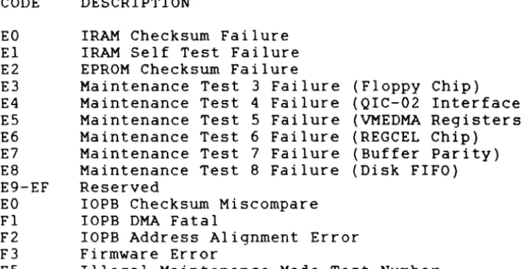
3.4 FATAL ERROR REGISTER
If a fatal error occurs, the 732 returns the appropriate Completion Code in this register. Table 3-2 lists the fatal error codes; Section 6.5 describes them.
CODE EO E1 E2 E3 E4 E5 E6 E7 E8 E9-EF EO Fl F2 F3 F5
DESCRIPTION
IRAM Checksum Failure IRAM Self Test Failure EPROM Checksum Failure
Maintenance Test 3 Failure (Floppy Chip)
Maintenance Test 4 Failure (QIC-02 Interface) Maintenance Test 5 Failure (VMEDMA Registers) Maintenance Test 6 Failure (REGCEL Chip)
Maintenance Test 7 Failure (Buffer Parity) Maintenance Test 8 Failure (Disk FIFO) Reserved
IOPB Checksum Miscompare IOPB DMA Fatal
IOPB Address Alignment Error Firmware Error
Illegal Maintenance Mode Test Number
TABLE 3-2. FATAL ERROR CODES
[image:23.620.158.537.238.434.2]SECTION 4: IOPB DESCRIPTION
4.0 GENERAL
The Input/Output Parameter Block (IOPB) passes messages between the 732 and host software: software passes the type of transfer, disk address, data address, and count to the 732; the 732 returns the transfer status and possibly the ending addresses upon command completion. This section begins with the standard IOPB for most data transfer commands and follows with variations of the lOPB.
4.1 STANDARD lOPB The 732 uses the standard commands and some general unit number is selected. when the tape unit number
floppy lOPB for data transfer purpose commands, when a floppy
4.1.1 IOPB Byte 0 (Command)
ERROR SUMMARY DONE
CHAIN ENABLE SCATTER/GATHER COMMAND
BIT MNEMONIC DESCRIPTION
I 7 I 6 I 5 I 4 I 3 I 2 I 1 1 0 1
7 ERRS ERROR SUMMARY - ERRS is only valid if DONE is set. When set, a hard or soft error occurred during IOPB processing. When clear, the 732 successfully completed the lOPB.
6 DONE DONE - When set, the IOPB is complete; if chained, software may remove the IOPB from the chain. Software must reI ink the chain in the same order as before, and cannot move IOPBs in memory.
5 CHEN CHAIN ENABLE - When set, the Next IOPB
Address Modifier and Next IOPB Address point to the next chained lOPB. When clear, this IOPB is not chained to another IOPB. If CHEN and IEC are set, the 732 returns the whole chain with one RIO; if CHEN is set and IEC is clear, the 732 returns one IOPB at a time. 4 SGM SCATTER/GATHER MODE - When set, the IOPB is
either a scatter (read) or a gather (write) transfer; a linked list describes the number of 16-bit words and to what address the 732 transfers each section of the data. The link address modifier and the link address specify the link list location. When clear, this IOPB specifies the data transfer address; the data is transferred to/from contiguous
memory. SGM is only valid for standard Reads and Writes.
3-0 COMM COMMAND - See Table 4-2.
4.1. 2 IOPB Byte 1 (Status Byte I)
After the 732 executes the IOPB, it sets DONE and posts a Completion Code in this byte. (Completion Codes are only valid if DONE is set.) A code of Ox indicates a successful completion; any other value indicates an error occurred (See Section 6).
4.1.3.1 IOPB Byte 2 (Status Byte 2) for FLOPPY DISK
IOPB Byte 2 is the Disk Status byte; it is only valid if DONE is set.
BIT 7 6
5-4
3
2
1
o
I 7 I 6 I 5 I 4 I 3 I 2 I 1 1 0 1
I
RESERVED
I
RESERVED 1 1
RESERVED -==-=-_____________________ 1 ___ 1
ATTENTION HIGH RESERVED
COMMAND C-O-M=P=L=E=T=E---DRIVE READY
MNEMONIC
ATTN
CMPL
DRDY
DESCRIPTION RESERVED.
RESERVED. RESERVED.
ATTENTION HIGH - The 732 sets ATTN when the drive reports an error.
RESERVED.
/
COMMAND COMPLETE - The 732 sets CMPL when the currently selected drive is ready to accept a command.
4.1.3.2 IOPB Byte 2 (QIC02 status 0) for TAPE BIT 7 6 5 4 3
MNEMONIC DESCRIPTION STO
CNI
DFF
WP
EOM
SET - if any other bit in byte 0 is set. If bit 7 is set Exception may be set.
CARTRIDGE NOT IN - Exception set if cartridge removed, and (1) drive selected by select drive with Lock Cartridge command; (2) motion command is issued; or (3) tape moved
previously from BOT.
DEVICE FAULT FLAG - No longer unselected drive (USL) bit. DFF sets Exception. Must be followed by a Read Status sequence to clear Exception. (Read Extended Status III contains information in Byte 25 to determine cause of fault.) DFF set when formatter
detects 540 condition which prohibits further command execution.
1. No tape motion (jammed cartridge).
2. Failure to recognize or exit area between BOT/load point, or early warning/EaT. 3. No tach pulses.
4. Failure to complete command function in specified internal time. For example: not completing rewind once formatter initiates command.
DFF indicates an unrecoverable 540 or cartridge error to user.
WRITE PROTECTED CARTRIDGE - Set if cartridge write protect mechanism on safe. Remains set
if any Vrite or Erase command is issued when cartridge is write protected.
END OF MEDIA - Set when early warning hole detected on last track in write mode.
Remains set while tape is at logical end of media. Not reset by Read Status. Vhen set, Exception is set.
4.1.3.2. IOPB Byte 2 (QIC02 Status 0) for TAPE (continued) BIT MNEMONIC DESCRIPTION
2 UDE UNRECOVERABLE DATA ERROR - Set for
unrecoverable data error during read or write operation. If set, Exception is set. Reset by Read Status.
1 BNL BAD BLOCK NOT LOCATED - Set to indicate drive not able to locate correct block on tape. If set, Exception is set. When set with (UDE), drive transfers filler data block or data from a different block to keep correct total block count. BNL reset by Read Status.
o
FMD FILEMARK DETECTED - Set when filemark block is read. Exception set and FMD reset by Read Status.4.1.4.1. IOPB Byte 3 (Status Byte 3) for FLOPPY DISK IOPB Byte 3 is reserved. It reflects the 732's internal status and may be a non-zero value.
4.1.4.2. BIT
7
6
5
IOPB Byte 3 (QIC02 Status 1) for TAPE MNEMONIC DESCRIPTION
STI
ILL
NDT
SET If any other bit in Byte 1 is set. If set, Exception may be set.
ILLEGAL COMMAND - Exceptions and Bit 6 set under these conditions:
1. On line not asserted when read or write type command attempted or in process. 2. Non-implemented command is issued. 3. Non-read type command issued without
proper termination of read sequence. 4. Non-write type command issued without
proper termination of write sequence. ILL reset by Read Status.
4.1.4.2. IOPB Byte 3 (QIC02 Status I) for TAPE BIT MNEMONIC DESCRIPTION
4 MBD MARGINAL BLOCK DETECTED - Set at detection of marginal data block. Enhanced track offset
read recovery uses MBD to alert host if q4-mil or q8-q4-mil offset required to read
recorded cartridge. Exception set only if Exception and filemark read status are indicated. A set MBD indicates track position offset, when filemark was read. This status indicates to host a marginally recorded cartridge. Host may determine to write append tape, or recover data and rewrite cartridge.
3 BOM BEGINNING OF MEDIUM - Bit set when drive is logically at BOT, Track
O.
If set, Exception is set. Bit not reset by Read Status, but reset when tape moved away from logical BOT. 2 BPE BUS PARITY ERROR - Bit set when drive detectsodd parity error on bus during data transfer to drive. If set, Exception is set. Odd parity is an odd number of active bits on bus. Parity is enabled by W8, W9, WIO jumper configuration on 540 formatter. Only data checked for parity.
I ERM END OF RECORDED MEDIA - Bit set when drive detects end of recorded media, or following a Seek End of Data command. If set, Exception
is set.
o
4.1.5
POR POWER ON/RESET OCCURRED SET - Bit set
following power on to drive or a reset from host. If set, Exception is set. Bit reset by a Read Status.
IOPB Byte 4 (Subfunction)
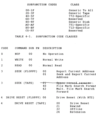
IOPB Byte 4 is the Subfunction byte. Subfunction Codes follow a convention that indicates whether the code is generic to all VME controllers, generic to a group of controllers (i.e., disk, tape, etc.), or specific to a particular controller (See Table 4-1).
4.1. 5 IOPB Byte 4 (Subfunction) (continued)
The 732 combines standard Command Codes with Subfunction Codes to execute commands. The IOPB Command Code and Subfunction Code fields define the required operation. Table 4-2 lists the 732 Command and Subfunction Codes.
CODE
o
1 2 3 3SUBFUNCTION CODES CLASS 00-IF 20-3F 40-5F 60-7F 80-9F AO-AF BO-BF CO-FF
Generic To All Generic Tape 772-Specific Reserved Generic Disk 751-Specific 712-Specific Reserved TABLE 4-1. SUBFUNCTION CODE CLASSES
COMMAND SUB FN DESCRIPTION NOP 00
WRITE 00 READ 00 SEEK (FLOPPY)
SEEK (TAPE)
No Operation Normal Write Normal Read 00
01
21 40 42
Report Current Address Seek and Report Current Address
Spaee reeo~ rev@~
File Mark Search Forward Mult. File Mark Search
Forward
4 DRIVE RESET (FLOPPY) 00 Drive Reset (With RTZ)
4 DRIVE RESET (TAPE) 00 21 22 24
Drive Reset Rewind
Offline Retension
[image:30.621.150.555.247.726.2]4.1.5. IOPB Byte 4 (Subfunction) (continued) CODE COMMAND SUB FN DESCRIPTION
5
6
7
WRITE PARAMETERS
READ PARAMETERS
EXTENDED VRITE (FLOPPY)
00 Vrite Controller Prmtrs. 80 Vrite Drive Parameters 00 Read Controller Prmtrs. 40 Read QIC02 Status
80 Read Floppy Drive Parameters
81 Vrite Track Format
7 EXTENDED WRITE (TAPE) 20 Vrite File Mark 21 Erase
8 EXTENDED READ 81 Verify Data - not implemented
83 Read Full Track
9 DIAGNOSTICS 00 Self Test
A-F RESERVED
4.1. 6
BIT
7
TABLE 4-2. 732 COMMAND/SUBFUNCTION CODES (continued)
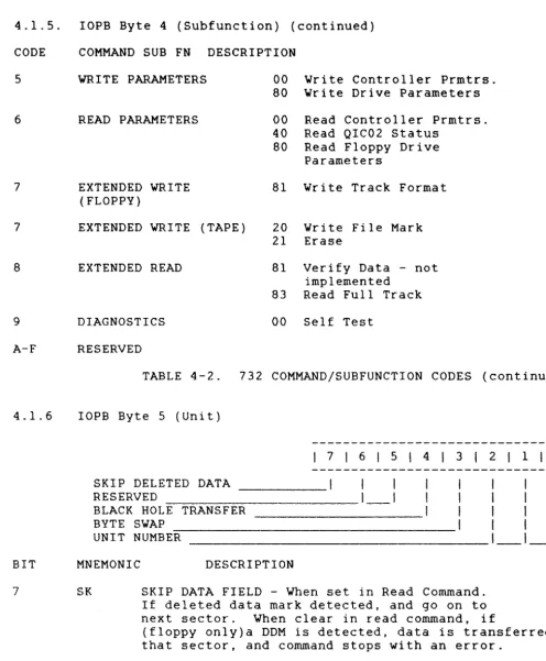
lOPB Byte 5 (Unit)
SKIP DELETED DATA RESERVED
BLACK HOLE TRANSFER BYTE SWAP
UNIT NUMBER
I 7 I 6 I 5 I 4 I 3 I 2 I 1 1 0 1
MNEMONIC DESCRIPTION
SK SKIP DATA FIELD - When set in Read Command. If deleted data mark detected, and go on to next sector. When clear in read command, if
(floppy only)a DDM is detected, data is transferred frl that sector, and command stops with an error.
[image:31.623.88.584.145.746.2]4.1. 6 BIT 7-5 4 3 2-0 4.1. 7
IOPB Byte 5 (Unit) (continued) MNEMONIC BHT BS UNIT LOGICAL 0 1 2,3 4 5 6,7 DESCRIPTION RESERVED.
BLACK HOLE TRANSFER - When set, the 712 does not increment the bus address during a data transfer; IOPB transfers occur normally. When clear, the 732 does increment the bus
address.
BYTE SWAP - Each word transfer
UNIT NUMBER - This value specifies the Unit Number of the attached drive to which the transfer is directed.
UNIT SELECTION
UNIT BIT BIT BIT DRIVE
0 0 0 Floppy Unit
0 0 1 Floppy Unit
0 1 X Reserved
1 0 0 Tape Unit 1
1 0 1 Reserved
1 1 X Reserved
IOPB Byte 6 (Interrupt Level)
1 2
I 7 I 6 I 5 I 4 I 3 I 2 I 1 , 0 , LINK LIST LENGTH
INTERRUPT LEVEL
_________ ' __ 1 __ 1 __ 1 __ 1
1
I
I
---1---1---1
BIT MNEMONIC DESCRIPTION
7-3 LLL LINK LIST LENGTH - Bits 7-3 specify the length, in elements, of a linked list for Scatter/Gather commands. Each element
4.1.7 IOPB Byte 6 (Interrupt Level) (continued) BIT MNEMONIC DESCRIPTION
2-0 INTL INTERRUPT LEVEL - The 732 uses these bits as the VMEbus hardware interrupt level when it completes the IOPB. The 732 will not
interrupt if bits 0 through 2 are clear.
4.1.8
NOTE
Depending on the command, Bytes 6 through 13 have different definitions
(See Sections 4.2 through 4.4). IOPB Byte 7 {Interrupt Vector}
IOPB Byte 7 determines the interrupt vector that the 732 uses upon command completion. This byte is not valid if the
interrupt level is zero.
4.1.9 IOPB Bytes 8 and 9 {count}
Byte 8 is the Count High; Byte 9 is the Count Low. The bytes specify the number of disk sectors or tape blocks to be transferred in a data transfer IOPB.
The disk format command uses this count to specify the number of tracks to format.
The tape Multiple File Mark Search command uses this count to specify the number of contiguous file marks to be found. If an error occurs, these bytes indicate the residual count, i.e. the number of sectors or blocks not transferred. A count of 0 is illegal, and the lOPB returns a completion code 013H.
4.1.10 lOPB Bytes A-D
These Bytes are used differently for floppy disk data
transfer commands, tape data transfer commands and parameter commands. See section 4.2 and 4.3 for usage in parameter commands.
4.1.11 lOPB Bytes A-D for Floppy Disk 4.1.11.1 lOPB Byte A
4.1.11.2 IOPB Byte B (Cylinder)
This byte specifies the starting cylinder address for a data transfer.
4.1.11.3 IOPB Byte C (Head)
• This byte specifies the starting head address for a data transfer. Only heads 0 and 1 are valid.
4.1.11.4 rOPB Byte D (Sector)
This byte specifies the starting head address for a data transfer. The controller adds 1 to the logical sector number before addressing the drive, unless the SZV bit is set.
4.1.12 rOPB Bytes A-D for QIC02 Tape 4.1.12.1 IOPB Bytes A and B
These bytes contain the Re-write count for a write operation if a QIC02 error occurred, or if the drive status is read.
4.1.12.2 IOPB Bytes C and D
These bytes contain the Re-read count for a read operation if a QIC02 error occurred, or if the drive status is read. 4.1.13 rOPB Byte E (Data or Link Address Modifier)
I
7I
6I
5I
41
3121
1101
RESERVED I I I 1 1 I I
DATA OR LINK ADDRESS MODIFIER _ _ _
1_1_1_1_1_1
BIT DESCRIPTION7-6 RESERVED.
4.1.14 IOPB Byte F (Next IOPB Address Modifier)
I 7 1 6 I 5 1 4 I 3 1 2 1 1 1 0 1 I 1 1 1 1
RESERVED 1 1 I 1 1 1
NEXT lOPB ADDRESS MODIFIER ________ 1 _ _ 1 _ _ 1 _ _ 1 _ _ 1 _ _ 1 BIT MNEMONIC DESCRIPTION
7-6 RESERVED.
5-0 NEXT IOPB ADDRESS MODIFIER - The Next IOPB address Modifier, along with the Next IOPB Address, point to the next IOPB in the chain.
4.1.15 IOPB Bytes 10 through 13 (DMA Data Address)
IOPB Byte 10 is DMA Data Address High; Byte 13 is DMA Data Address Low. These bytes comprise the data or link list
address pointers. The 732 uses these bytes with the data or link list address modifier to point to the data or linked list address. If SGM is set, this address points to the linked list; if SGM is clear, this address points to the data address.
4.1.16 IOPB Bytes 14 through 17 (Next IOPB Address)
IOPB Byte 14 is Next IOPB Address High; Byte 17 is Next IOPB Address Low. These bytes comprise the Next lOPB Address pOinters. The 732 uses these bytes with the Next IOPB
Address modifier to point to the next IOPB in the chain {if CHEN is set in Byte O}.
4.1.17 lOPB Bytes 18 and 19 (lOPB Checksum)
Byte 18 is rOPB Checksum High; Byte 19 is IOPB Checksum Low. The 732 calculates the checksum by adding the IOPB bytes. See Section 8.15.
4.2 CONTROLLER PARAMETERS lOPB
This rOPB sets and reads various controller parameters. The 732 uses the standard IOPB, but redefines bits in Bytes 8,
9, A, B, C, and E.
CONTROLLER PARAMETERS
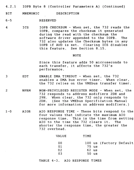
4.2.1IOPB Byte 8 (Controller Parameters A)
I 7 I 6 I 5 141 3 I 2 I 1 101 AUTO-UPDATE
RESERVED
IOPB CHECKSUM
ENABLE DMA TIMEOUT
NON-PRIVILEGED REGISTER MODE
I
I
I
I
1 I AIO RESPONSE TIME _______________________________ 1 ___ 1 BIT MNEMONIC DESCRIPTION7 AUD AUTO-UPDATE - When set, the 732 updates the IOPB to the transfer's correct ending
parameters; it updates the disk address, the sector count, and the data address after completing the transfer or detecting an
4.2.1 BIT 6-5 4 3 2 1-0
IOPB Byte 8 (Controller Parameters A) (Continued) MNEMONIC DESCRIPTION
ICS
EDT
NPRM
AIOR
RESERVED
IOPB CHECKSUM - When set, the 732 reads the IOPB, compares the checksum it generated during the read with the checksum the
software driver appended to the IOPB. The 732 also updates the Checksum bytes in any IOPB if AUD is set. Clearing ICS disables this feature. See Section 8.15.
NOTE
Since this feature adds 50 microseconds to each transfer, it affects the 732's
performance.
ENABLE DMA TIMEOUT - When set, the 732
enables a DMA bus error timer. When clear, the 732 relies on the VMEbus transfer timer. NON-PRIVILEGED REGISTER MODE - When set, the 732 responds to address modifiers 2DH and 29H. When clear, the 732 only responds to 2DH. (See the VMEbus Specification Manual for more information on address modifiers.) AIO RESPONSE TIME - These bits respond to the
four values that indicate the maximum AIO response time. This is the time from setting AlO to the time the 732 clears it. The
shorter the response time, the greater the 732 overhead.
VALUE TIME
00 100 us (Factory Default)
01 75 us
02 62 us
03 50 us
TABLE 4-3. AlO RESPONSE TIMES
[image:37.621.77.543.146.738.2]4.2.2 IOPB Byte 9 (Controller Parameters B)
171 615 1
4I
31
21
1101
THROTTLE DEAD TIME RESERVED
_ _ _ _
I _ I
11
RELEASE ON REQUEST
1
1
1
1
RESERVED
_____________________________ 1 __ 1_1 __ 1
BIT MNEMONIC DESCRIPTION7-6
TDT THROTTLE DEAD TIME - TDT selects one of four minimum time periods that determines the timethe 732 remains off the bus between throttle bursts (See Section 8.12).
5
4
3-0 4.2.3
BIT
7-6
ROR
RESERVED.
RELEASE ON REQUEST - When set, the 732
releases the bus at the request of other bus masters; otherwise, it continues with the next throttle burst. The 732 monitors the bus request lines and releases bus busy only
if another bus request is pending. It
completes its specified throttle burst before releasing the bus due to a pending request. When clear, the 732 releases the bus at the end of each throttle burst and rearbitrates
if more data transfers are pending. RESERVED.
IOPB Byte A (Controller Parameters C)
I
7161
5141
31
2I
1101
RESERVED _ _ _ _ _ _ _ _ _ _
1_1
1
INTERRUPT AT END OF CHAIN ,
AUTOMATIC SEEK RETRY I 1 1 I
RESERVED _ _ _ _ _ _ _ _ _ _ _ _ _ _ _ _ _
I _ I _ I
__ I
4.2.3. rOPB Byte A (Controller Parameters C) (Continued) BIT MNEMONIC DESCRIPTION
5 IEC INTERRUPT AT END OF CHAIN - When set, the 732 returns all IOPB chains with one RIO and one interrupt; it does not reI ink or unlink
IOPBs. The RIO address of a completed chain is the address of the first IOPB in the
chain. The 732 also uses the interrupt level and vector of the first lOPB in the chain. Clearing IEC disables this feature. (Do not set or clear IEC while the 732 is processing an lOPB chain.)
4
3-0
4.2.4
ASR AUTOMATIC SEEK RETRY - When set, the 732 resets the drive, seeks to the commanded
cylinder and retries the transfer on Seek and Header Error/Cylinder errors.
RESERVED.
IOPB Byte B (Controller Parameters D)
Bits 0 through 7 are the Throttle (THRO) bits. The throttle is the maximum number of transfers allowed each time the 732 becomes bus master. The throttle value determines the
maximum DMA burst length for both data and IOPB DMA
transfers. Each bit position represents a binary weight, allowing a throttle from 1 to 256.
VALUE WEIGHT
0 256
1 1
2 2
3 3
255 255
TABLE 4-4. THROTTLE VALUES 4.2.5 lOPB Byte C (Release Level)
The 732 returns its release level on a Read Controller Parameters command.
[image:39.623.89.539.122.751.2]4.2.6 lOPB Byte E (Controller Type)
IOPB Byte E is the Controller Type byte. Xylogics assigns each VME controller a unique controller type code.
4.2.7
CONTROLLER 712
732 751 772
CODE (H) 12
32 51 72
(ESDI Disk Controller)
(Floppy & QIC02 Controller) (SMD/SMD-E Controller)
(Pertec Tape Controller)
TABLE 4-5. CONTROLLER TYPE CODES
lOPB Bytes 10 and 11 (EPROM Part Number)
The 732 returns a portion of the EPROM part number on a Read Controller Parameters command. The 4 nibbles in these 2 bytes refer to the part number's last 4 digits. For
example, if the part number is 180-002-151, Byte 10 holds 21H and Byte 11 holds 51H.
4.2.8 lOPB Byte 12 (Revision)
This byte contains the revision level of the EPROM plugged into the board (O=Unreleased Prototype, l=A, 2=B, etc.). 4.2.9 lOPB Byte 13 (Subrevision)
This byte contains the subrevision level of the EPROM
4.3 DRIVE PARAMETERS IOPB (Floppy only)
DRIVE PARAMETERS
4.3.1. IOPB Byte 5 (Unit)
I
7I
6I
5141
3I
2I
1101
RESERVED I 1
SECTOR ZERO VALID
I
I
I
I
RESERVED _ _ _ _ _ _ _ _ _ _ _ _ _ _ _
1_1_1_1
UNIT4.3.1 BIT 7-6 5
4-1
o
4 . 3 . 1
IOPB Byte 5 (Unit) (continued) MNEMONIC
SZV
UNIT
DESCRIPTION RESERVED.
SECTOR ZERO VALID - If set, the first sector on the media sector is O. If clear, the
first sector on the media is sector 1 (normal mode).
RESERVED.
UNIT - If set command applies to Drive 2, if clear command applies to Drive 1.
IOPB Byte 6 (Drive Parameters)
I 7 161 5 141 3 I 2 1 1 101 DOUBLE STEP
MFM
I
II
I
MULTI TRACK PRECOMP
SPEED 1 I I
INTERRUPT LEVEL ____________________________ 1 ___ 1 ___ 1 BIT MNEMONIC DESCRIPTION
7 DSTP DOUBLE STEP - When the seek distance from the present cylinder to the required cylinder is doubled. and that number of step pulses is issued to the drive. It allows a 48TPI disk to be read on a 96TPI drive.
6 MFM When set the media is read and written in MFM mode. When clear, FM encoding is used.
4.3.1 lOPB Byte 6 (Drive Parameters) (continued) BIT MNEMONIC DESCRIPTION
4 PCMP PRECOMPENSATION - When set all MFM data is precompensated by ql25ns, regardless of cylinder. When clear, MFM data written to cylinders less than 28 are precompensated by l87ns. 3 2-0 4.3.2 SPD INTL
SPEED - When set dual spindle speed drives are run at 300 revs/minute. When clear, the drive runs at 360 revs/minute.
INTERRUPT LEVEL
IOPB Byte 8 (Head Load Time)
Byte 8 is the Head Load Time in milliseconds, values 2-254ms. Recommended value for the TOSHIBA ND-08DE is 36ms. 4.3.3 lOPB Bytes 9 and A (Gap 3 length)
4.3.3.1IOPB Byte 9 specifies the length of GAP 3 used in Read and Write operations.
4.3.3.2l0PB Byte A specifies the length of GAP 3 used in Format operations.
4.3.3.3Recommended values of GAP 3 for 5," drives (from NEC fPD765A manua I) .
R&W
MFM MODULATION SECTOR SIZE N GPL
0 FM 128 0
0 FM 256 1
0 FM 512 2
0 FM 1024 3
1 MFM 256 1
1 MFM 512 2
1 MFM 1024 3
1 MFM 2048 4
4.3.4 IOPB Byte B (Max Cylinder)
lOPB Byte B specifies the maximum cylinder number to be accessed on the selected drive. For an 80 cylinder drive the value will be 79 = 4F hex.
4.3.5.IOPB Byte C (Sector Size and Max Head)
Bits 7-4 specify the number of bytes per sector, they represent the variable 'n' recorded in the media header.
n
0001 0010 0011
bytes per sector 256
512 1024
Bits 3-1 are reserved and must be set to O. Bit 0 if set, specifies a drive with two heads. If clear, the drive has only one head or only head 0 will be used on the media. 4.3.6. IOPB Byte D (Max Sector)
IOPB Byte D specifies the drive's maximum sector value. This value is 0 based. For example, on a drive with 8
sectors, the maximum sector is specified as 7. All starting sector numbers for data transfers are specified in the range 0-7. If the SZV bit is set, data transfer is started from the sector with that value on its header. If the SZV bit is clear, one is added to the sector number in the IOPB, and the data transfer is started from that sector, as there is no sector 0 on the media.
4.3.7. IOPB Byte E (Timing) 4.3.7.1. Head Unload Time
Bits 7-4 specify the time to delay before unloading the heads after a data transfer operation has completed. The value is increments of 16ms from 1=16ms to F=240ms. The user may select any value, short times give minimum head wear, but longer access time for a follow-on command which must start with a head load.
4 . 3 . 7 .2. Step Rate
SECTION 5: COMMANDS 5.0 GENERAL
Each disk command begins a new page. An IOPB diagram follows each command description. The diagrams are
highlighted to indicate which bytes the 732 requires for command execution, and which bytes return after execution. Each 732 IOPB is 26-bytes long. All commands use Bytes 0 through 19H. Reserving all 26 bytes maintains IOPB
integrity.
5.0.1 Setting Up the Command
Each IOPB diagram indicates the bytes or fields that must be set for each operation. Certain parameters are essential; others are optional. All commands require the Command, Unit, and Interrupt Level fields to contain valid
information. (This is also true for the Interrupt Vector field if the Interrupt Level is not zero.)
5.0.2 Completing the Command
After the 732 completes the command, it updates IOPB Bytes 0 through 3 with ERRS, DONE, a Completion Code, and an
internal status. The 732 only updates the entire IOPB if Auto-update (AUD) is enabled, an error occurs, or if Read
Parameters, Report Current Address or Read Status commands are executed. If AUD is set, and no errors occur, the 732 sets DONE, posts a Completion Code of zero in Byte 1, and disk drive status information in Byte 2; for any command
that DMAs data to/from memory, the 732 updates the data address to point to the last address plus one of the
transfer. See Table 5-1. STATUS ACTION
AUD Clear/No Error732 updates Bytes 0-3 with ERRS, DONE, Occurs Completion Code, and
internal status
AUD Set/No Error Occurs732 updates entire lOPB AUD Clear/Error Occurs732 updates the entire IOPB AUD Clear/A Read Params732 updates the entire IOPB Report Current Address or
Read Status Command is Executed
5.1 NO OPERATION
The No Operation (NOP) command is a diagnostic tool. The 732 reads the IOPB and marks it complete.
5.2 WRITE DATA
The 732, after reading and decoding the IOPB, positions the disk drive heads at the target cylinder; it then reads in
the data from the host (indicated by the IOPB) and writes the data contiguously to the disk's sequential sectors. Write Data has two IOPB formats: Normal and Scatter/Gather. A Normal IOPB specifies one contiguous block of host memory to write to the disk. A Gather Write IOPB specifies up to 32 different blocks of host memory to be placed in
contiguous sectors on the disk (See Section 8.11).
If the BS bit is set in IOPB Byte 5, the high and low byte in each word are swapped.
WRITE DATATAPE
5.3 READ DATA
The 732, after reading and decoding the IOPB, positions the disk drive heads at the target cylinder, then reads the disk data indicated by the IOPB, and writes the data in host
memory.
Read Data has two IOPB formats: Normal and Scatter/Gather. A Normal IOPB specifies one contiguous block of host memory
that is used when placing the data from the disk. A Scatter Read IOPB specifies up to 32 different blocks of host memory where the disk data will be placed (See Section 8.11).
If the BS bit in IOPB byte 5 is set, the high and low byte in each word are swapped. See Section 4.1.6 for handling of deleted data dependant on the SK bit.
5.4 REPORT CURRENT ADDRESS (Floppy only)
The 732 selects the disk drive, reads the first good header field, and returns the address to the host via the IOPB; it updates the IOPB regardless of AUD's status.
REPORT CURRENT ADDRESS
5.5 SEEK AND REPORT CURRENT ADDRESS (Floppy only) The 732 issues a seek to the selected disk drive for the target cylinder. After the drive completes the seek, the 732 reads the first good header field it encounters and reports it to the host via the completed lOPB. The 732 updates the lOPB regardless of AUD's status.
5.6 POSITION (Tape only)
The position commands move tape forward and reverse over records or files, without transferring data. The 732 uses the count field to set up the number of file marks to search for.
POSITION
5.6.1. Position Subfunction Codes CODE DESCRIPTION
21
40 FILE MARK SEARCH FORWARD - Searches forward the number of file marks specified in the count field. Each
count placed the tape heads in the interrecord gap just after the file mark in questions. If this
command is issued, and there are no file marks on the tape, the 772 searched until it detects EOT.
42 MULTIPLE FILE MARK SEARCH FORWARD - Searches forward for a specified number of consecutive file marks. This is especially useful for positioning the tape heads at the logical end of tape (usually indicated by several consecutive file marks). This command follows the same completion rules as File Mark Search Forward.
5.7 DRIVE RESET 5.7.1. Floppy Disk
The 732 issues commands to the disk drive to reset. First it issues a fault clear, and then a recalibrates (return to zero). The IOPB is complete when the recalibrate completes or times out on drives that are ready. The 732 does not wait for the recalibrate to complete on drives that are not ready.
5.7.2.Tape
The 732 issues a drive reset to the QIC02 interface. DRIVE RESET TAPE
5.7.3 CODE 00
21
22
24
Drive Reset Subfunction Codes DESCRIPTION
DRIVE RESET - Resets the tape drive by pulsing the reset line. Use this command if a tape runaway
condition occurs. Always consider the tape position unknown following a Drive Reset.
REWIND - Moves the tape at high speed in the reverse direction until the BOT marker is detected. The tape drive should indicate it is at BOT or load point. The Rewind command completes immediately. although the tape is still rewinding. To verify the tape drive has completed rewinding, software must issue a Read Drive Status command. The following conditions should be true: BOT set, REW clear, and DRRDY set. (Caution: even if REW is clear, the drive may not be ready [DRRDY clear].)
OFFLINE - Removes the online signal from the QIC-02 interface, causing the drive to write a file mark if the previous command was a write, and to initialise a rewind command. All other commands leave the drive online.
5.8 WRITE CONTROLLER PARAMETERS
This command initializes the 732 with its operational parameters. No default parameters are assumed, but once
loaded, the parameters remain stored in the 732 volatile memory until the controller is powered down. Section 4.2 defines how to change the parameters for individual
applications; Section 6.6 explains the IRAM checKsum. WRITE CONTROLLER PARAMETERS
5.9 WRITE DRIVE PARAMETERS (Floppy only)
This command informs the 732 of the disk drive's physical characteristics. No default values are assumed, but once loaded, the parameters remain stored in the 732 volatile memory until the controller is powered down. See Section 4.3.
The disk address bytes OB-OD specify the maximum cylinder, head and sector on the media.
5.10 READ CONTROLLER PARAMETERS
The 732 returns the current 732 operational parameters to the host via the lOPB; it verifies the lRAM checksum before completing the transfer regardless of AUD's status. See Section 4.2.
READ CONTROLLER PARAMETERS
5.11 READ DRIVE PARAMETERS (Floppy only)
The 732 returns the disk drive's physical characteristics to the host via the rOPB. The 732 verifies the IRAM checksum before completing the transfer; it updates the IOPB
5.12 READ STATUS BYTES (Tape only)
The 732 reads the QIC02 drive interface's status bytes. It returns drive-specific status and diagnostic information in the IOPB. Consult your drive manufacturer's manual for the definitions for read status O. This command is always sent to the drive by the controller if an exception occurs.
READ STATUS
5.11 WRITE TRACK FORMAT (Floppy only)
The Write Track Format command directs the 732 to format the drive, writing the header of all sectors with the
appropriate sector rD. The data field contains zeros and a valid ECC. The Count bytes in this command refer to the number of tracks to be formatted. See Section 8.3.
5.12 EXTENDED WRITE (Tape only)
This command controls two separate Write functions: Write File Mark and Erase. These functions require different IOPB formats. Section 5.12.1. explains these functions and
follows with IOPB diagrams. 5.12.1 Write File Marks CODE DESCRIPTION
20 WRITE FILE MARK - The 732 issues a Write File Mark command to the tape drive. File marks are special records that logically group data records on tape. Host software should write at least one file mark, preferably two, at the logical end of the tape.
(Write File Mark uses the count field to specify the number of file marks to write.)
WRITE FILE MARK
5.12.2 Erase Tape CODE DESCRIPTION
21 This command erases the whole tape from BOM to EOT and rewinds to BOM.
5.13 VERIFY DATA - NOT IMPLEMENTED
This command verifies the data on the disk. The 732 reads the data from the host and the disk simultaneously, and
compares them on a bit-by-bit basis. The granularity of the mismatch reporting is one sector. The ending data address does not indicate where a mismatch error occurred.
VERIFY DATA
5.14 DIAGNOSTICS
The 732 executes the on-board self test diagnostics. Do not chain this lOPS to another lOPS. It cannot be used in
SECTION 6: ERROR PROCESSING