Microstructure and Mechanical Property of 5000 Series Aluminum Stud Joint
with Zinc Insert Using Friction Welding
*1Taichi Nishida
1;*2, Tomo Ogura
1, Mitsuo Fujimoto
2and Akio Hirose
11Division of Materials and Manufacturing Science, Osaka University, Suita 565-0871, Japan 2Kawasaki Heavy Industries Ltd., Kobe 650-8670, Japan
Friction stud welding with zinc insert was applied to 5000 series aluminum alloys. A cone-shaped A5056 stud bolt was successfully friction-welded onto A5083 plate at low torque using zinc insert compared to that without zinc insert. This is considered to be contributed by a eutectic reaction between aluminum and zinc, which can effectively remove the oxide film and promote the joining. With bigger torque and longer welding time, the amount of residual zinc was reduced and high strength was achieved. On the other hand, a twist break between the stirred zone and the stud bolt increased during friction and this causes the decrease of tensile strength of the joint after a certain amount of torque. The results of micro-tensile test showed that strength at the edge of joint interface was higher than that at the center area regardless of zinc insert. From the experimental results, the joining process of the present friction stud welding classified into five processes, i.e. wear of stud bolt, start of joining, increase of tensile strength, decrease of tensile strength, and fracture during friction. [doi:10.2320/matertrans.L-MZ201124]
(Received October 1, 2010; Accepted January 28, 2011; Published April 20, 2011)
Keywords: aluminum stud joint, friction welding, zinc insert, micro-tensile test
1. Introduction
5000 series aluminum alloys are widely used in the structures that require low-temperature properties and corrosion resistance.1) The joining of the stud bolt in these alloys is mainly performed by arc stud welding.2,3)However,
quality of the joints depends on worker’s skill, and the removal of the oxide film on the aluminum surface is necessary before welding.4)Recently, friction stud welding
has been applied to overcome these problems in arc stud welding.2,5)This method is a modified friction welding, and
can achieve steady quality of joints because welding only proceeds by prearranged parameters. Furthermore, the oxide film at the interface of the joint is efficiently removed during friction stage.6–8) To remove the oxide film easier, the stud
bolt has a corn shaped tip, and zinc insert is applied between the stud bolt and the base material.2,9–12) Therefore, the joining process of the friction stud joint is considered to be quite unique and distinctive compared with other conven-tional friction welding.13–15)
To optimize the welding parameters in friction stud welding, it is necessary to precisely understand the joining process and its mechanism. In the present study, micro-structures at the interface of stud joints were observed, and tensile test was conducted to evaluate the mechanical properties with varying friction torque. Moreover, micro-tensile test was also conducted to evaluate the mechanical properties at each region of the interface in micro-scale area. To clarify the effect of zinc insert on the joining process and the joint properties, the joints without zinc insert were also evaluated. From the obtained results, joining process of the present friction stud welding was discussed.
2. Experimental Procedure
The corn shaped A5056 stud bolt with 8 mm in diameter was friction welded onto A5083 plate (designated as base material) using a direct drive welding machine. The zinc primer with 100mmthick was applied between the stud bolt and the base material. During the welding, the rotation speed and the friction load were set to 6000 rpm and 1800 N, respectively. The friction torque was varied from 0.8 to 4.0 Nm and 1.0 to 3.0 Nm in the joint with and without zinc insert, respectively. The friction torque was monitored using a load cell through an A/D converter with a sampling time of 0.01 s. The rotation of the stud bolt stops and goes onto upset stage when the friction torque reaches at a setup value. Upset load and upset time were set to 2000 N and 3.2 s, respectively.
For the microstructural observation, the joint was cut vertically, mechanically polished, and etched with Keller’s etchant or Tucker’s etchant. Microstructural observation was performed using a stereomicroscope (SZX7, OLYMPUS Inc.), optical microscope (OPTIPHOT-100, NIKON Inc.) and scanning electron microscope (SEM; S-3000H, HITACHI Inc.). Tensile test (5505, INSTRON Inc.) and micro-tensile test were performed to evaluate the mechanical properties of the friction stud joint with a cross-head speed of 5:00102mm/s and 1.00mm/s, respectively. The
shapes of the specimens are shown in Fig. 1.
3. Results
3.1 Microstructures of friction stud joints
Figure 2 shows a typical image of the interface of the friction stud joint without zinc insert (Torque: 2.0 Nm). A lens shaped stirred zone was observed between the stud bolt and the base material (inside dotted lines). The stirred zone became larger with bigger friction torque. In this study, the joint interface was designated as three areas, i.e. center area, middle area and edge area. The center area and the edge area
*1The Paper Contains Partial Overlap with the ICAA12 Proceedings by USB under the Permission of the Editorial Committee.
mean the center of the rotated stud bolt and the edge of the joint interface, respectively. The middle area is located in the middle of the center and the edge area.
Figure 3 shows a typical image of the interface of the friction stud joint with zinc insert (Torque: 2.0 Nm). Residual zinc was clearly observed between the stirred zone and the base material at the center and the middle area (Fig. 3(b)). Although the residual zinc decreased with increasing friction torque, it could not be completely exhausted from the joint
interface in the present welding conditions. A break between the stud bolt and the stirred zone (Fig. 3(d), designated as twist break) was observed at the edge area. When a friction torque increased, this twist break increased along the boundary between the stud bolt and the stirred zone, where the microstructures of the stud bolt were much plastically deformed.
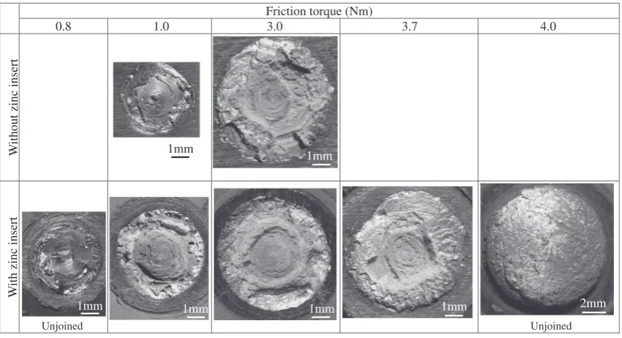
3.2 Tensile test and fracture surface observation Figure 4 shows tensile strength of each joint. In the joints without zinc insert, strength was obtained with the torque of 1.0 Nm and increased with friction torque to 3.0 Nm. In the joint with zinc insert, joining could not be achieved with the torque of 0.8 Nm. Joining was achieved from the torque of 1.0 Nm and this strength was higher than that of the joint without zinc insert. Tensile strength increased with friction torque until 3.0 Nm, similar to the joint without zinc insert. After showing maximum strength at 3.0 Nm, strength of the joint began to decrease gradually with larger friction torque, and joining could not achieved again when the torque was 4.0 Nm.
SEM images of the fracture surface of the joints are shown in Fig. 5. Three types of fracture morphology, i.e. shear fracture (Fig. 5(a)), ductile fracture (Fig. 5(b)) and interfacial fracture (Fig. 5(c)) were observed. The shear fracture was seen where twist break was located between the stud bolt and the stirred zone as seen in Fig. 2. This break is considered to
1.5 0.7
0.7 R0.15
1.6
0.35
t =0.4 unit : mm 2.2 1.2
(b)
15 15 30
(a)
Φ12
Φ8
Fig. 1 Dimension of the specimens for (a) tensile test and (b) micro-tensile test.
500µm Middle
Center Stud bolt
Base material
Edge
Fig. 2 Optical microstructure of the cross section appearance of the friction stud joint without zinc insert. (Torque¼2:0Nm).
(b)
(c) (d)
(b)
500μm
(c) Base material
Stud bolt
200μm 200μm 200μm
(a)
(d) Middle
Center Edge
Residual zinc
Twist break Residual zinc
[image:2.595.75.263.72.236.2] [image:2.595.85.511.422.509.2] [image:2.595.72.524.559.759.2]occur at the initiating during the friction stage because the fracture surface was flat and traces of rubbing were seen. Ductile fracture occurred at base material when the joining was achieved at the joint interface. Interfacial fracture between the stirred zone and the base material showed laminar surface along the rotation direction.
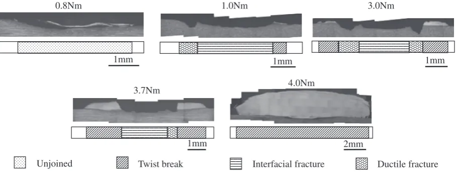
The appearance of the fracture surface and its cross section of each joint was given in Figs. 6–8, respectively. In the joint without zinc insert, the fracture at the torque of 1.0 Nm was mainly interfacial fracture (Figs. 6 and 7). At a torque of 3.0 Nm, the joined area was larger than that of 1.0 Nm because the joining progressed with larger friction torque. The fracture mode was partly changed to ductile fracture.
In the joints with zinc insert, the surface of the joint with the torque of 0.8 Nm was shiny as shown in Fig. 6. In the joints with the torque of 1.0 and 3.0 Nm, as shown in Fig. 8, while the area of the interfacial fracture decreased, the ductile fractured region and twist break region increased as the joining progressed. The twist break which generated from the edge of the joint interface increased into center, and finally the joint fractured during the friction. This is the reason why the joint strength decreases from the torque 3.0 to 4.0 Nm.
The obtained result indicates that zinc insert is effective to join at lower torque. However, the joint strength with zinc insert decreased at lower torque such as 2.0 Nm and 3.0 Nm. This is considered to be caused by the residual zinc at the joint interface as seen in Fig. 3.
0 100 200 300
T
ensile strength,
σ
/ MP
a
Friction torque, T / Nm
1.0 2.0 3.0 0.8 1.0 2.0 3.0 3.5 3.7 4.0
Without zinc insert With zinc insert
Fig. 4 Tensile strength of the friction stud joints with/without zinc insert.
200μm
(c) (b)
(a)
200μm 200μm
Fig. 5 SEM images of three types seen in the fracture surface of the joint. (a) Shear fracture at twist break area between stud bolt and stirred zone, (b) ductile fracture at base material and (c) interfacial fracture between stirred zone and base material.
Friction torque (Nm)
0.8 1.0 3.0 3.7 4.0
W
ithout zinc insert
W
ith zinc insert
1mm 1mm
1mm 1mm 2mm
1mm
1mm
Unjoined Unjoined
[image:3.595.66.274.73.204.2] [image:3.595.75.524.353.467.2] [image:3.595.71.526.523.770.2]3.3 Micro-tensile test
[image:4.595.106.494.76.168.2]In the section 3.2, the fracture surface observation showed that several types of fracture occurred even in one friction stud joint. To evaluate the mechanical property of each region in more detail, micro-tensile test was performed at the center, middle and edge area of the joint interface as shown in Fig. 9. Micro-tensile test of the specimens of the base material and the stud bolt was also performed. The result of micro-tensile test of each area is given in Fig. 10. In the joints without zinc insert, only the center area could be measured at 1.0 Nm because the joined area was very small as shown in Fig. 6. The strength showed lower than that of the base material and the stud bolt. As the joined area increased at 3.0 Nm, the strength of the center and the edge area could be measured. The strength of each area increased up to that of
4.0Nm 3.7Nm
3.0Nm 1.0Nm
1mm
1mm 2mm
1mm 0.8Nm
1mm
Interfacial fracture
Twist break Ductile fracture
Unjoined
Fig. 8 Cross section appearances of the fracture surface of joints with zinc insert (base material’s side). The types of fracture are also shown.
1mm 1mm
Interfacial fracture
Twist break Ductile fracture
1.0Nm 3.0Nm
Fig. 7 Cross section appearances of the fracture surface of joints without zinc insert (base material’s side). The types of fracture are also shown.
Center Edge
500μm
Middle
Fig. 9 A typical image of measured areas for micro-tensile test (with zinc insert, 3.0 Nm).
0 100 200 300 400
T
ensile strength,
σ
/ MP
a
(a) Center (b) R/2 (c) Edge Without zinc insert With zinc insert
1.0Nm Base
material Stud bolt
(a) (a) (c) (a) (c) (c) (a) (b) 3.0Nm
1.0Nm 3.0Nm
[image:4.595.72.526.220.391.2] [image:4.595.90.523.443.566.2] [image:4.595.318.534.608.756.2]the base material and the stud bolt. In the joints with zinc insert, the strength of both the center and the edge area could be measured at 1.0 Nm. The strength of edge area was as high as base material’s one. At 3.0 Nm, the joined area was also larger than that of the same torque without zinc insert. The strength of each area was similar to the base material or stud bolt’s one.
Regardless of zinc insert, all joints showed the higher strength in the edge area than in the center area. Figure 11 shows the fracture location of micro-tensile test specimen. The specimens with low strength, such as the center area of 1.0 Nm with/without zinc insert, fractured at the joint interface as shown in Fig. 11(a). On the other hand, the specimens with high strength, such as the edge area of 1.0 Nm with zinc insert and each area of 3.0 Nm with/ without zinc insert, mainly fractured at the boundary between the stud bolt and the stirred zone. These specimens showed dimple fracture.
4. Discussion
From the obtained results, the effect of zinc insert on the bondability of the joint and the friction stud welding process are discussed as follows.
4.1 Effect of zinc insert
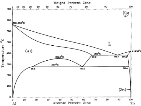
The joint with zinc insert has larger joined area than that of the joint without zinc insert, and it also showed higher strength at 1.0 Nm as shown in Figs. 4 and 6. These results indicate that the area that metallurgical joining was achieved became larger by zinc insert at early stage of welding process. Fuwano et al.16) found that the maximum temper-ature at the joint interface reached more than 700 K at A5052 side during conventional friction welding of A2017/A5052. This is higher than the melting point of zinc (693 K). Moreover, according to the Al-Zn binary phase diagram17)as shown in Fig. 12, Al-Zn eutectic point (654 K) is lower than aluminum melting point (933 K). Therefore, it is suggested
that Al-Zn eutectic reaction firstly occurs during friction, and the oxide layer on the surface of the base material was removed easily. So the metallurgical joining begins earlier at the interface and the strength became larger than that of joint without zinc insert at the beginning of joining process (1.0 Nm) as shown in Fig. 4.
On the other hand, although zinc is exhausted as friction torque becomes bigger, it could not be exhausted completely. Micro-tensile test showed that residual zinc at the center area causes the decrease of the joint strength (Figs. 10 and 11). Therefore, it is considered that the center area with residual zinc insert is harmful to the joint property. The thickness and distribution initial zinc insert should be optimized to improve joint property though the successful exhaust of zinc insert.
4.2 Friction stud welding process
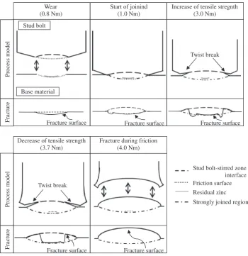
Schematic illustration of the joining process of the joint using zinc insert is given in Fig. 13. The process of friction stud welding in this study goes through five steps as described below.
(1) Wear (friction torque: 0.8 Nm, friction time: 0.38 s). When the friction stud welding starts, both stud bolt and base material begin to wear. The friction surface enlarges peripherally and moves into the base material because of the corn shaped tip of the stud bolt. The heat input time also differs between the center and the edge area of the friction surface. So the lens shaped stirred zone (dashed line), forms in the stud bolt (Fig. 2). Zinc insert and oxide film at the edge area are removed due to the rotation of the stud bolt. However, the joining is not achieved because of the low heat input at this stage. Therefore, the stud bolt and base material separate easily.
(2) Start of joining (friction torque: 1.0 Nm, friction time: 0.50 s).
Joining begins when the friction torque increases to around 1.0 Nm. The joining is partly achieved from the edge area (dashed-dotted line), of which micro-tensile strength was almost equal to that of the base material (Fig. 10(c)). This is caused by higher heat input at the edge area. At center area (dotted line), although the joining is achieved, the strength was lower because of lower heat input, as shown in the result of micro-tensile test (Fig. 10(a)). As increasing heat input,
Joint interface
Base material
Stud bolt
Stirred zone
(b)
500
μ
m
[image:5.595.56.283.68.256.2](a)
[image:5.595.306.545.70.250.2]Fig. 11 Fracture location of the micro-tensile test specimen. (a) Fractured at the interface of the joint (with zinc insert, 1.0 Nm, center) and (b) fractured between the stud bolt and the stirred zone (with zinc insert, 3.0 Nm, middle).
zinc insert is gradually exhausted to outside of the stud bolt and the strongly joined region increases to center. While strength of the joint increases with friction torque, the twist break initiates from the edge area during friction. This twist break gradually grows toward the center area along the boundary between stud bolt and stirred zone, where micro-structures of the stud bolt were much plastically deformed with increasing friction time.
(3) Increase of tensile strength (friction torque: 3.0 Nm, friction time: 0.85 s).
When friction torque reaches a certain value (3.0 Nm in this study), tensile strength becomes highest as shown in Fig. 4. Fracture surface and its cross section appearance (Figs. 6 and 8) showed that the propagation of twist break occurs not along the boundary between the stud bolt and the stirred zone but inside the stirred zone. However, the result of micro-tensile test shows that stirred zone is stronger than the boundary between the stud bolt and the stirred zone (Fig. 11(b)). This is considered that, when the friction stud joint is deformed, fracture initiates at center area (dotted line), and then propagates to edge area along the joint interface before the twist break propagates. When the fracture from the center area is close to the twist break, shear stress occurs within stirred zone. Finally, the joint fracture through the crack passes inside the stirred zone. (4) Decrease of tensile strength (friction torque: 3.7 Nm, friction time: 1.12 s).
With friction torque bigger than a certain value, twist break initiated during friction is close to the center area. Therefore, the strength of the joint gradually decreases due to the decrease of the joined area.
(5) Fracture during friction (friction torque: 4.0 Nm, friction time: 5.70 s).
The twist break at the boundary between the stud bolt and the stirred zone continues propagating and finally reaches to the center area. Therefore, fracture occurs completely at the boundary during friction stage and the stud bolt and base material separate by itself.
5. Conclusions
In the aluminum stud joint with/without zinc insert using friction welding, microstructure observation was performed at the interface, and tensile test was conducted to evaluate the mechanical properties. Micro-tensile test was also performed to evaluate the micro-scale mechanical properties at each area of the interface of joints. The obtained results are summarized as follows.
(1) Zinc insert was effective to join at a lower torque and shorter friction time through Al-Zn eutectic reaction.
(2) Oxide film at the surface of both stud bolt and base material was sufficiently removed and joint was achieved. Lens shaped stirred zone at the stud bolt and the twist break were observed. Zinc insert was removed when friction torque
Wear (0.8 Nm)
Start of joinind (1.0 Nm)
Increase of tensile stregnth (3.0 Nm)
Decrease of tensile strength (3.7 Nm)
Fracture during friction (4.0 Nm) Stud bolt
Base material
Stud bolt-stirred zone interface
Process model
Process model
Fracture
Fracture
Fracture surface Fracture surface Fracture surface
Fracture surface Fracture surface
Twist break
Twist break Friction surface Residual zinc
[image:6.595.122.473.70.432.2]Strongly joined region
increased, but could not be exhausted completely from the interface.
(3) With bigger torque and longer welding time, the amount of residual zinc was reduced and high strength was achieved. On the other hand, twist break between stirred zone and stud bolt increased during friction, and this causes the decrease of the tensile strength of the joint after a certain amount of torque.
(4) Micro-tensile test showed that the strength at the edge of the joint was higher than that at center area regardless of zinc insert.
(5) From the obtained results, the friction stud welding of the present study was able to explain by five process; wear of stud bolt, start of joining, increase of tensile strength, decrease of tensile strength, and fracture during friction.
Acknowledgements
The author would like to thank Prof. F. Minami, Prof. M. Ohata and Dr. Y. Takashima of Osaka University for their significant help with micro-tensile test. A part of this work was supported by Priority Assistance for the Formation of Worldwide Renowned Centers of Research—The Global COE Program (Project: Center of Excellence for Advanced Structural and Functional Materials Design) from the Ministry of Education, Culture, Sports, Science and Tech-nology (MEXT) and Grant-in-Aid for Young Scientists (B) No. 21760585, Japan.
REFERENCES
1) L. F. Mondolfo:Aluminum alloys: structure and properties, (Butter-worths, Boston, London, 1976) pp. 806–819.
2) S. Koga, H. Nishida, S. Fukada, G. Nishiyama and K. Kitabayashi: Kawasaki Jukou Giho166(2008) 34–37.
3) I. Samardzic, I. Kladaric and S. Klaric: Metalurgija48(2009) 181–186. 4) C. Menzemer, P. C. Lam, T. S. Srivatsan and C. F. Wittel: Mater. Lett.
41(1999) 192–197.
5) Andreas W. E. Nentwig and Andreas Jenicek: Weld. Cutting7(1994) 36–40.
6) M. Rao and T. H. Hazlett: Weld. J.49(1970) 181s–188s.
7) N. Yamamoto, M. Takahashi, M. Aritoshi and K. Ikeuchi: Q. J. Jpn. Weld. Soc.23(2005) 496–503.
8) M. Maalekian: Sci. Technol. Weld. Joining12(2007) 738–759. 9) M. Movahedi, A. H. Kokabi and H. R. M. Hosseini: Mater. Charact.60
(2009) 441–446.
10) Z. Xu, J. Yan, B. Zhang, X. Kong and S. Yang: Mater. Sci. Eng.415
(2006) 80–86.
11) T. Watanabe, Y. Tanaka, A. Yanagisawa, S. Onuma and S. Sato: Q. J. Jpn. Weld. Soc.10(1992) 470–476.
12) T. Watanabe, Y. Tanaka, A. Yanagisawa, S. Onuma and S. Sato: Q. J. Jpn. Weld. Soc.10(1992) 477–483.
13) K. Katoh and H. Tokisue: J. JILM49(1999) 553–558.
14) M. Kimura, M. Kusaka, K. Seo and A. Fuji: Sci. Technol. Weld. Joining10(2005) 378–383.
15) M. Kimura, M. Kusaka, K. Seo and A. Fuji: Sci. Technol. Weld. Joining11(2006) 209–215.
16) H. Fuwano, K. Katoh and H. Tokisue: J. JILM50(2000) 157–161. 17) T. B. Massalski, J. L. Murray, L. H. Bennett and H. Baker:Binary Alloy