ISSN Print: 2331-4222
DOI: 10.4236/wjet.2018.62020 May 15, 2018 315 World Journal of Engineering and Technology
Determination of Bonding Failures in
Transparent Materials with Non-Destructive
Methods—Evaluation of Climatically Stressed
Glued and Laminated Glass Compounds
Christin Sirtl
1, Matthias Kraus
1, Christiane Hadlich
2, Andrea Osburg²
1Department of Steel and Hybrid Structures, Bauhaus University of Weimar, Weimar, Germany
2Department of Building Chemistry and Polymer Materials, Bauhaus University of Weimar, Weimar, Germany
Abstract
As part of an international research project—funded by the European Un-ion—capillary glasses for facades are being developed exploiting storage energy by means of fluids flowing through the capillaries. To meet highest visual demands, acrylate adhesives and EVA films are tested as possible bonding materials for the glass setup. Especially non-destructive methods (visual analysis, analysis of birefringent properties and computed tomograph-ic data) are applied to evaluate failure patterns as well as the long-term beha-vior considering climatic influences. The experimental investigations are pre-sented after different loading periods, providing information of failure devel-opments. In addition, detailed information and scientific findings on the ap-plication of computed tomographic analyses are presented.
Keywords
Non-Destructive Testing, Bonding Methods, Computed Tomography
1. Introduction
In order to meet European climate regulations [1], large facades are to be active-ly involved in the energy suppactive-ly of buildings. The high transmission of glass panes can be utilized to harvest solar energy and to contribute to the building technology system [2].
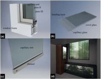
Within the framework of a research project, rolled capillary glasses are devel-oped to be applied in insulating glass units (IGU) as shown in Figure 1(a). The
How to cite this paper: Sirtl, C., Kraus, M., Hadlich, C. and Osburg, A. (2018) Deter-mination of Bonding Failures in Transparent Materials with Non-Destructive Me-thods—Evaluation of Climatically Stressed Glued and Laminated Glass Compounds. World Journal of Engineering and Tech-nology, 6, 315-331.
https://doi.org/10.4236/wjet.2018.62020
Received: February 21, 2018 Accepted: May 12, 2018 Published: May 15, 2018
Copyright © 2018 by authors and Scientific Research Publishing Inc. This work is licensed under the Creative Commons Attribution International License (CC BY 4.0).
DOI: 10.4236/wjet.2018.62020 316 World Journal of Engineering and Technology Figure 1. Capillary unit, (a) components integrated in IGU, (b) components of unit, (c) capillary unit with channel, (d) indoor view of IGU with integrated, colored capillary unit.
schematic setup of the units is presented in Figure 1(b). A fluid circulating through the capillaries enables an energy/heat storage and transfer by heat ex-changers. Two channels, which are arranged at the top and bottom of the pane and which are connected to the building technology system (Figure 1(c)), dis-tribute the fluid to and collect it from the capillaries. Next to the energy saving and insulating function of the IGU (see Figure 1(d)), further applications are possible. The capillary unit can for example be used as a direct heating or cool-ing device in this context. It can also be applied in partition walls of offices or public buildings to contribute to a comfortable room climate. Furthermore, the employed fluid can be enhanced to a magneto-active liquid, enabling tunable shading functions (see [3]).
The bonding between capillary and cover glass has to satisfy high demands in terms of strength, transparency and durability (Table 1). However, the long-term behavior is influenced by atmospheric impacts (temperature change, fluid contact, UV irradiation) as well as static loads (wind suction and pressure, capillary pressure of the fluid).
DOI: 10.4236/wjet.2018.62020 317 World Journal of Engineering and Technology Table 1. Required criteria of bonded glass-glass connections.
Visual requirements Long-term resistance against Mechanical requirements
- Highly transparent joint over time - Colorless
- Non-porous
- Temperature - Humidity
- Fluid (glycol mixture) - UV-radiation
Durable load-bearing functioning and high adhesion of the connection in a temperature range of −20˚C to +80˚C and under fluid attack
Two different types of bonding materials are chosen for testing, namely acry-late adhesives and EVA films. UV-curing acryacry-late adhesives meet the visual re-quirements, which is one of the highest priorities in the selection of the bonding materials. In addition, an EVA film (ethylene vinyl acetate copolymer film) is tested as a bonding material. As suitable material for glass lamination [4], it is chosen for reasons of strength and high transparency, whereas the material be-havior for artificial aging is to be analyzed.
2. Components and Bonding Materials
The functional capillary unit (capillary glass, bonding layer and cover glass) con-sists of a glass pane with capillary structure made of soda lime silicate glass (produced in float process) and of a 0.75 mm thin glass made of modified and chemically prestressed aluminosilicate glass. In the modifying process, the ther-mal expansion coefficient and the refractive index are adjusted to the float glass. The characteristic properties of the two glasses are compiled in Table 2.
As mentioned above, UV-curing acrylates and EVA films are tested for their possible application in the capillary unit as bonding layer. Due to the molecular structure, acrylates are assigned to thermoset providing resistance and stiffness, respectively, at serviceability temperature ranges by close-meshed polymers. The mostly one-component materials can be applied and processed without any dif-ficulties. Regarding the experimental scheme, three acrylate urethanes (urethane systems supplemented by nitro groups) are analyzed, curing by UV radiation and polymerization within a few minutes and without any additional pressure. In the following evaluation and discussion, one of the acrylates is focused and referred to as “A” as specified in Table 3. Further details on the acrylate experi-ments including all test series can be found in [7].
DOI: 10.4236/wjet.2018.62020 318 World Journal of Engineering and Technology Table 2. Characteristic properties of bonded components [5][6].
Property Float glass (capillary glass) Modified aluminosilicate glass
Density [kg/m3] 2500 2477
Bending tensile strength [N/mm2] 45 200 Young’s Modulus [N/mm2] 70,000 74,000 Middle thermal coefficient of
expansion [1/K] 9.0 × 10⁻⁶ 8.8 × 10⁻⁶
[image:4.595.206.539.244.346.2]Refractive index ≈1.52 1.508
Table 3. Characteristic properties of bonding materials—information based on manu-facturer specifications [9][10].
Property Acrylate (A) EVA (D) Density [g/cm3] 1.0 0.95 - 0.97 Tensile strength [N/mm2] 33 > 20
Elongation at tear [%] 4 >700 Young’s Modulus [N/mm2] 1600 No specification
Refraction index 1503 1480
characteristic properties of the material focused in the following evaluations are compiled in Table 3, where one of two analyzed EVA films is focused referred to as experimental series “D”.
3. Experimental Approach
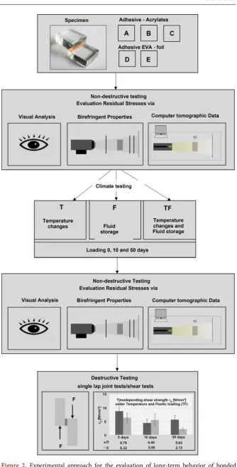
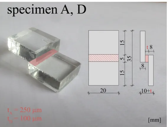
Figure 2 presents the experimental scheme applied to several test series and spe-cimens, respectively. Unified testing procedures for lap joint tests are specified in codes, however, generally for connecting metals [11] [12]. The design of the glass specimens is therefore adjusted to testing procedures of material manufac-turers [13]. The glass components to be joined are 20 by 20 mm with thickness of 8 mm and the overlapping length is 5 mm, s. Figure 3. The thickness of the bonding layer depends on the material. For acrylates it is set to 250 µm and for the EVA films presented here to 100 µm (D).
Aging is defined as totality of physical and chemical material changes over time [14]. Various methods for characterization and quantification of these changes are distinguished [15]. On the experimental level, material aging is usually induced by accelerated artificial impacts in the sense of a time lapse [16] [17][18]. In doing so, the artificial simulations have to be adapted from realistic environmental influences. For the tests presented here, they have to in addition meet the requirements of Table 1.
DOI: 10.4236/wjet.2018.62020 320 World Journal of Engineering and Technology Figure 3. Test specimen for series A and D.
ambient temperatures. Since all materials/components are in direct contact with the fluid (glycol mixture), this is an additional influence to be considered. For this reason, three different climate settings are defined:
- alternating thermal stress (T) - fluidic storage (F)
- alternating thermal stress in combination with fluidic storage (TF)
The temperature regime for the thermal loading is chosen according to DIN EN 1942 [16] and ETAG 002 [19]. The temperature ranges between −20˚C and +80˚C in a time span of 21 h. During one cycle the temperature idles at −20˚C, +40˚C and +80˚C. The circulating fluid (glycol mixture) in the capillary glasses is used as a storage medium for the specimen. Each specimen of tests with fluidic influence (F) and combined loading (TF) is stored separately. Depending on the test series, the destructive and non-destructive tests are performed after 10 or 50 days of loading. Computed tomographic analyses are conducted on samples loaded for 10 days. In addition, some lap joint tests are performed on specimen without any influence of artificial aging as reference.
DOI: 10.4236/wjet.2018.62020 321 World Journal of Engineering and Technology conducted for all specimens. In addition, one specimen of each series is ex-amined by computed tomography.
4. Evaluation Methods
For the non-destructive testing, three different methods are applied. At first, a visual analysis is executed being the simplest practical approach to assess the quality of the connection and especially the optical requirements according to Table 1. Afterwards, birefringent properties of the specimens are analyzed, representing a commonly used method for analyzing glass residual stresses after forming processes (bottles, pre-stress glass structures, etc.). The last step is the evaluation of computed tomographic data, which is the most financial- and time-consuming method. It promises additional information, since transparent mediums have not often been analyzed yet.
4.1. Visual Analysis
The condition of adhesive bonds is described and evaluated by photographs. Amongst others, the following phenomena and damage patterns, respectively, can be detected:
- detachment of the adhesive from the components (delamination) - bubbles
- discoloration - cloudiness
- geometry anomalies of the layering
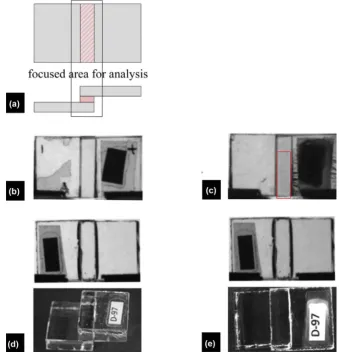
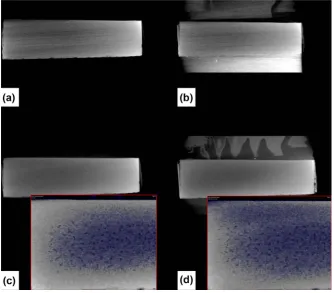
The cloudiness of an adhesive after artificial aging does not necessarily indi-cate a critical loss of strength, however, the material does not meet the optical demands defined in Table 1. The specimens are evaluated in the overlapping zone as depicted in Figures 4(a)-(c) show the analyses of specimen A112 (acry-late) before and after artificial aging (TF). Before loading, the visual examination does not reveal any disturbance in the overlapping area (Figure 4(a)), while af-ter 10 days of fluidic storage and alaf-ternating temperature loading, a slight clou-diness is detected appearing as grey dotted pattern (marked area in Figure 4(c)). The photographs of specimen D97 (EVA) before and after artificial aging are shown in Figure 4(d) and Figure 4(e). In compliance to the acrylate, no con-spicuity is detected previous to the aging process (Figure 4(d)). And even after 10 days of artificial aging (TF) no changes or damages are visibly recognizable (Figure 4(e)).
4.2. Birefringent Properties
DOI: 10.4236/wjet.2018.62020 322 World Journal of Engineering and Technology Figure 4. Visual analysis, (a) description of analyzed zone, (b) specimen A112—before climatic loading, (c) specimen A112—after climatic loading (10 days, TF), (d) specimen D97 before climatic loading, (e) specimen D97 after climatic loading (10 days, TF).
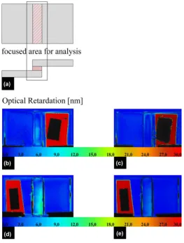
velocities of light for different spatial directions. When irradiated by polarized light, for example within a polarimeter, the light wave is split into two compo-nents running through the body at different speeds and therefore going along with a phase shift when exiting the specimen. This shift is referred to as optical retardation R [nm] and it gives a qualitative measure of the intrinsic stresses in the material (at constant sample thickness excluding birefringence). If R = 0, the system is at an optically isotropic state. The greater the optical path difference gets, the bigger the differences in the deflected light wavelengths and thus the stresses in the system are. However, only in exceptional cases, the size can be de-rived directly [20]. The method is therefore able to detect the qualitative distri-bution of the internal stresses.
DOI: 10.4236/wjet.2018.62020 323 World Journal of Engineering and Technology Figure 5, the results of specimens A112 (acrylate) and D97 (EVA) are shown. The dark red and black areas are caused by the labelling of the specimens (for reasons of identification). They are not considered in the evaluation, only the overlapping zone is of importance (Figure 5(a)). Before artificial aging, speci-men A112 shows certain stress differences in the lower bonding area (R ≈ 9.0 nm, Figure 5(b)). After aging of 10 days (TF), these differences disappear. The area of relaxation corresponds to the detected visual changes in Figure 4(c) (gray dotted area). An increase of stress differences is visible in the upper half of the bonding area.
For specimen D97, distinct stress differences (R ≈ 12.0 nm, Figure 5(d)) are visible in the total bonding area after the manufacturing process. After artificial aging of 10 days (TF), a slight decrease is noticeable (Figure 5(e)). This relaxa-tion is not detectable in the visual analysis (Figure 4(e)).
4.3. Computed Tomographic Analysis
Computed tomography is a non-destructive imaging method to acquire 3-dimensional data from different specimens based on 2D-X-ray photographs. For this purpose, the object is irradiated from several directions starting at 0 and rotating to 360 degrees. In-between rotation stops, an X-ray picture is taken. Af-terwards, all X-ray measurements are computed to a single volume data set. The number of pictures influences the quality of this set [21]. It contains voxel of different gray level, which mainly represent the attenuation of the X-ray beam at different positions. The attenuation depends on the material, the density, the thickness of material and the X-ray energy. The higher it is at a voxel position, the higher its gray level gets. Besides this favorable effect, undesirable effects called artefacts occur as well. Different artefacts have different causes, such as physical effects during the scan or the applied algorithms for reconstructing the data. To provide valid data from computed tomography it is important to reduce artefacts as good as possible and to identify remaining ones.
For the described experiments a nanotom m from GE is used. It runs with a 14-bit GE DXR detector with 3.072 × 2.400 pixel. To acquire and reconstruct the data, phoenix datos/x is applied and for the analysis and visualization of the data set, the software VG Studio MAX (Volume Graphics). For the scan the parame-ters listed in Table 4 are used.
These parameters applied to the described specimens lead to a resolution of 0.020888 mm in each direction, going along with corresponding minimum de-tectable details in this size. The resolution of the data set mainly depends on the size of the specimen and the used power. The higher the resolution, the better the detectability of small details.
DOI: 10.4236/wjet.2018.62020 324 World Journal of Engineering and Technology Figure 5. Optical retardation, (a) description of analyzed area, (b) specimen A112—before climatic loading, (c) specimen A112—after climatic loading (10 days, TF), (d) specimen D97 before climatic loading, (e) specimen D97 after climatic loading (10 days, TF).
[image:10.595.241.508.481.680.2]DOI: 10.4236/wjet.2018.62020 325 World Journal of Engineering and Technology Table 4. Parameters used in the CT scanning process.
Parameter Value
Voltage 120 kV
Current 80 µA
Modus 1
Scan duration 1 hour
Target Diamant
Number of pictures 1200
Section 1, the bonding is examined in the middle of the layer. As further repre-sentation, an integrated layer image with a thickness of 1 mm is produced: the gray values of all layer images (0.5 mm to the right and left of the cutting plane and in the middle of the adhesive layer) are summarized, averaged and represented as one image. With the help of this method, certain effects are to be clarified and compared with the representations of the visual analysis and repre-sentation of the optical retardation. In the reconstructed images, stripes are sometimes visible (see, for example, Figure 7(a)). These do not characterize dif-ferent X-ray densities in the material but represent an artifact which frequently occurs in computed tomographic analyzes of vitreous bodies.
Specimen A112 does not show irregularities in the individual layer images within the bonding before loading (Figure 7(a) and Figure 7(b)). After an ar-tificial aging process of 10 days (TF), small cracks are visible in the acrylate (Figure 7(c) and (Figure 7(d)) with length of 0.10 mm to 0.26 mm. In an en-largement, these cracks can be detected over the entire adhesive layer thickness (highlighted blue by threshold methods). In the integrated layer image these ir-regularities are also clearly visible (Figure 7(d)). The cracks revealed by the computed tomographic images are not recognizable in the visual analysis. They are an indication of the stress reduction, which is clearly detectable by the de-crease of optical retardation (Figure 5(c)).
The computed tomographic image in the middle of the bonding layer of spe-cimen D97 (Figure 8(a)) shows a certain lined structure (highlighted in dark blue). However, this phenomenon is not related to the material but based on ar-tefacts. After the aging process of 10 days TF, it is not visible anymore. In com-parison to specimen A112 (Figure 7(d)), the blue coloring in Figure 8(b) does not reveal any specific changes due to the climatic loading.
4.4. Destructive Testing
DOI: 10.4236/wjet.2018.62020 326 World Journal of Engineering and Technology
Figure 7. Computed tomographic images of specimen A112—computed tomographic
data before (a) image in the middle of bonding layer, (b) average result over bonding layer) and after climate loading (TF) of 10 days, (c) middle of bonding layer, (d) average result over bonding layer with blue highlighting of density differences).
Figure 8. Computed tomographic images of specimen D97—computed tomographic
data before (a) image in the middle of bonding layer) and after climate loading (TF) of 10 days (b) image in the middle of bonding layer with blue highlighting of density dif-ferences).
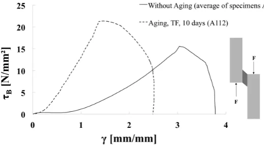
[image:12.595.207.539.430.597.2]DOI: 10.4236/wjet.2018.62020 327 World Journal of Engineering and Technology Figure 9. Lap join test—τB-γ diagram, bonding material A—without aging effects (average of series A) and with aging effect TF, 10 days (specimen A112).
Figure 10. Lap join test—τB-γ diagram, bonding material D—without aging effects (average of series D) and with aging effect TF, 10 days (specimen D97).
over time—indicated by the decreased strain ability with a simultaneous increase of shear strength (Figure 9, Aging, TF, 10 days, specimen A112). This is also in-dicated by the results of the computed tomographic data (Figure 7): the small cracks point to this conclusion as well. The material behavior of different speci-mens in this series shows a wide variety regarding stiffness as well as shear strength under aging effects. Furthermore, the failure mode is not consis-tent—both, cohesion and adhesion failures are observed. The aging under tem-perature changes and fluidic storage seems to have diverse influences on the material. However, a cause investigation of the phenomenological effects is not accomplishable using the described methods and not subject of this research.
DOI: 10.4236/wjet.2018.62020 328 World Journal of Engineering and Technology wide variety of shear strength, however, stiffness levels are always quite equal. As failure modus, an adhesion failure is observed for all specimens in this series. It seems that the artificial aging has negative influence on the bonding (adhesion forces) in the interface layer. Specific influences leading to this failure cannot be detected in the computed tomographic data (Figure 8). However, with the analysis of birefringent properties a decrease of optical retardation (Figure 6) is visible.
5. Results
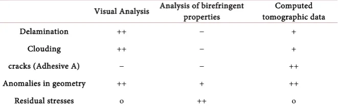
Based on the analyzed samples of all testing series, Table 5 assesses the detection quality of various damage phenomena. Computed tomographic images provide more detailed information of phenomena already detectable with the visual analysis. The evaluation of the optical retardation gives very general information on current states of bonding layers. With the 2D picture a specification where stress changes over the thickness of the specimen occur is not possible. With a full 3D CT scan, this lack of information can be closed. Moreover, destructive testing is very important to evaluate the detected phenomena. Important infor-mation can be derived from testing to connect material phenomena to mechani-cal behavior.
Regarding the polymers tested, damage is already evident after 10 days under combined loading of fluidic storage and temperature gradients. For acrylate A as bonding layer, the damage is clearly visible using CT images and it is verified in the destructive testing as well. For bonding material D, less aging influences are visible in the presented non-destructive testing methods. However, the influence on the mechanical behavior (especially the strength) is obvious.
Based on the assigned task, choosing suitable materials for bonding glass de-vices (Figure 1), material D is chosen. Albeit mechanical changes due to the ag-ing process can be detected, the specimen shows very high optical stability over the testing time.
6. Conclusions
In this contribution, acrylate and EVA materials for bonding glass panes are examined under the aspects of optical and mechanical requirements (Table 1). Bonded and artificially aged specimens are analyzed with three different non-destructive testing methods (visual, birefringent properties, computed to-mography) to evaluate influences of aging processes on the connection. In addi-tion, destructive tests are performed.
DOI: 10.4236/wjet.2018.62020 329 World Journal of Engineering and Technology Table 5. Evaluation of non-destructive testing methods on transparent connections un-der climatic loading.
Visual Analysis Analysis of birefringent properties tomographic data Computed
Delamination ++ − +
Clouding ++ − +
cracks (Adhesive A) − − ++
Anomalies in geometry ++ + ++
Residual stresses o ++ o
detection of damage mechanism with non-destructive testing methods after artificial aging (10 days TF) (++ very good, + good, o not possible, − bad).
exemplify changes in the bonding layer. Here, the decrease in shear strength is effected by the interface layer between glass and EVA film. These results are confirmed by destructive tests.
All methods presented are somehow useful for the phenomenological detec-tion of aging effects on transparent bonds. However, the detectable phenomena differ and depending on the method, the density of information is quite differ-ent. Computed tomographic images can provide detailed information on aging phenomena. However, CT analyses are time-consuming, costly, applicable only to limited sizes of specimens and therefore not addressed in practical applica-tions and investigaapplica-tions in general. By evaluating the destructive and non-destructive analyses, damage pattern of bonded connections can be identi-fied and taken into account for improved material models of numerical simula-tions leading to optimized approximation of mechanical behavior.
Acknowledgements
The authors gratefully acknowledge financial support from the European Un-ion’s Horizon 2020 research and innovation program under grant agreement No 637108. We acknowledge further financial support by the Open Access Publica-tion Funds of the Bauhaus University of Weimar.
References
[1] Comission, E. (2016) Buildings.
https://ec.europa.eu/energy/en/topics/energy-efficiency/buildings
[2] Heiz, B.P.V., Pan, Z., Lautenschläger, G., Sirtl, C., Kraus, M. and Wondraczek, L. (2017)Smart Windows: Ultrathin Fluidic Laminates for Large-Area Façade Integra-tion and Smart Windows. Advanced Science, 4.
http://onlinelibrary.wiley.com/doi/10.1002/advs.201600362/full
[3] Heiz, B.P.V., Pan, Z., Su, L., Le, S.T. and Wondraczek, L. (2018) A Large-Area Smart Window with Tunable Shading and Solar-Thermal Harvesting Ability Based on Remote Switching of a Magneto-Active Liquid. Advanced Sustainable Systems,
2. http://onlinelibrary.wiley.com/doi/10.1002/adsu.201700140/full
DOI: 10.4236/wjet.2018.62020 330 World Journal of Engineering and Technology lms/20161014_ABZ_evguard_Seite1.pdf
[5] Siebert, G. and Maniatis, I., Eds. (2012) Tragende Bauteile aus Glas—Grundlagen, Konstruktion, Bemessung, Beispiele. [Load-Bearing Glass Components—Basics, Design Dimensioning, Examples.] Ernst&Sohn, Berlin.
[6] Schott Technical Glass Solutions GmbH (2015) Schott Xensation Cover.
http://www.schott.com/d/xensation/a3f53d0a-586e-41b6-830c-48329da352c7/1.0/sc hott_xensation_cover_db_row.pdf
[7] Sirtl, C., Kraus, M., Hadlich, C., Osburg, A. and Wondraczek, L. (2017)Zur Bewer-tung klimatisch beanspruchter geklebter Glasverbindungen. [For the Evaluation of Climatically Stressed Bonded Glass/Glass Connections.] ce/papers, 1, 254-275.
http://onlinelibrary.wiley.com/doi/10.1002/cepa.26/full
[8] Folienwerk Wolfen GmbH (2018) The Clever Laminating Film.
http://www.evguard.net/de/
[9] DELO Industrie Klebstoffe (2014) Delo Photobond GB 310.
https://www.delo-adhesives.com/fileadmin/datasheet/DELO%20PHOTOBOND_G B310_%28TIDB-GB%29.pdf
[10] Folienwerk Wolfen GmbH (2017) Technical Data Sheet.
http://www.folienwerk-wolfen.de/fileadmin/upload/downloads/Glass-lamination_fi
lms/2017-08_Technical-Data_evguard_EN.pdf
[11] DIN Deutsches Institut für Normung e.V. (2009) Klebstoffe—Bestimmung der Zugscherfestigkeit von Überlappungsklebungen (DIN EN 1465:2009-07) [Adhe-sives—Determination of Tensile Lap-Shear Strength on Bonded Assemblies]. Beuth Verlag GmbH, Berlin.
[12] DIN Deutsches Institut für Normung e.V. (2011) Strukturklebstoffe—Bestimmung des Scherverhaltens struktureller Klebungen (DIN EN 14869:2011-07) [Structural Adhesives—Determination of Shear Behavior of Structural Bonds]. Beuth Verlag GmbH, Berlin.
[13] DELO Industrie Klebstoffe (2014) DELO Norm 5—Bestimmung von Druckscher-festigkeiten [DELO Guideline 5—Determination of Compressive Shear Strength]. DELO Industrie Klebstoffe, Windach.
[14] DIN Deutsches Institut für Normung e.V. (2012) Begriffe auf dem Gebiet der Alte-rung von Materialien—Polymere Werkstoffe (DIN 50035:2012-09) [Terms and De-finitions Used on Ageing of Materials—Polymeric Materials]. Beuth Verlag GmbH, Berlin.
[15] Ehrenstein, G.W. and Pongratz, S. (2007) Beständigkeit von Kunststoffen [Resis-tance of Plastics]. Carl Hanser Fachverlag, München.
https://doi.org/10.3139/9783446411494
[16] DIN Deutsches Institut für Normung e.V. (2004) Klebstoffe—Auswahlrichtlinien für Labor-und Alterungsbedingungen zur Prüfung von Klebverbindungen (DIN EN ISO 9142:2003) [Adhesives—Guide to the Selection of Standard Laboratory Ageing Conditions for Testing Bonded Joints]. Beuth Verlag GmbH, Berlin.
[17] DIN Deutsches Institut für Normung e.V. (2013) Kunststoffe—Künstliches Be-strahlen oder Gewittern in Geräte—Teil 2: Xenonbogenlampen (DIN EN ISO 4892-2:2013-06) [Plastics—Methods of Exposure to Laboratory Light Sources—Part 2: Xenon-arc lamps]. Beuth Verlag GmbH, Berlin.
DOI: 10.4236/wjet.2018.62020 331 World Journal of Engineering and Technology [19] Bundesministerium für Verkehr, Bau und Stadtentwicklung (1998) Bekanntma-chung der Leitlinie für die Europäische Technische Zulassung für geklebte Glaskonstruktionen—Teil 1: Gestützte und ungestützte Systeme (ETAG 002) [Structural Sealant Glazing Systems—Part 1: Supported and Unsupported Systems]. Beuth Verlag GmbH, Berlin.
[20] Katte, H. (2008) Bildgebende Messung der Spannungsdoppelbrechung in optischen Materialien und Komponenten [Imaging Measurement of Stress Birefringence in Optical Materials and Components]. Photonik, 05/2008, 60-63.
http://www.ilis.de/de/pdf/photonik_2008_05_60.pdf

![Table 2. Characteristic properties of bonded components [5] [6].](https://thumb-us.123doks.com/thumbv2/123dok_us/9291794.425487/4.595.207.540.92.197/table-characteristic-properties-bonded-components.webp)