© 2019, IRJET | Impact Factor value: 7.34 | ISO 9001:2008 Certified Journal | Page 2055
Modeling and Control of Three Phase BLDC Motor using PID and Fuzzy
Logic Controller
Prof. Manjusha D. Hedau
1, Mr. Harish D. Mude
2, Prof. P.V. Pullawar
31
Electrical Engineering, Dept. Jagadambha College of Engg tech. Yavatmal, Maharashtra
2
Electrical Engineer, Yavatmal, Maharashtra, India
3
Electrical Engineering Dept, Jagadambha College of Engg.Tech, Yavatmal, Maharashtra
---***---Abstract— Brushless DC (BLDC) motors are widely used for many industrial applications because of their high efficiency, high
torque and low volume. ) motors are employed in fans called super fans, electric and hybrid vehicles, industrial automation as actuators for industrial robots, extruder drive motors and feed drives for Computer Numerical Control (CNC) machine tools and home appliances ) motors are employed in fans called super fans, electric and hybrid vehicles, industrial automation as actuators for industrial robots, extruder drive motors and feed drives for Computer Numerical Control (CNC) machine tools and home appliances The aim of this research is to develop a complete model of the BLDC motor and to design an optimal controller for its position control. Generally PID controller is used for many control problems because of its simple structure and easy implementation. However in practice, we often do not get the optimum performance with the conventionally tuned PID controllers. For this purpose, A BLDC drive consists of a six switch inverter and Hall Effect position sensors. The speed regulation of sensorless BLDC drive using four-switch three-phase inverter BLDC motor and fuzzy controller is proposed here compared the PID controller and Fuzzy logic controller. The modeling, control and simulation of the BLDC motor have been done using the software package MATLAB/SIMULINK.
Keywords— Brushless DC motor, PID control, , Inverter Hall Effect Position Sensors, Fuzzy Logic Controller
1. INTRODUCTION
BLDC motors are very popular in areas which need high performance because of their smaller volume, high force, and simple system structure. Brushless Direct Current (BLDC) motors are AC synchronous motor with permanent magnets on the rotor and windings on the stator. Permanent magnets create the rotor flux and the energized stator windings create electromagnetic poles. The rotor is attracted by the energized stator phase In practice, the design of the BLDCM drive involves a complex process such as modeling, control scheme selection, simulation and parameters tuning etc. An expert knowledge of the system is required for tuning the controller parameters of servo system to get the optimal performance. Recently, various modern control solutions are proposed for the optimal control design of BLDC motor [1][2]. However, these methods are complex in nature and require excessive computation. In contrast, PID control provides a simple and yet effective solution to many control problems [3].
Although PID controllers have a simple structure but it is quite challenging to find the optimized PID gains. The continuing performance improvements of computational systems have made Genetic Algorithm (GA) appropriate for finding global optimal solution for control system such as the search of optimal PID controller parameters [4][5].
© 2019, IRJET | Impact Factor value: 7.34 | ISO 9001:2008 Certified Journal | Page 2056
II. MODELING PID CONTROLLERFig. 1 shows the basic building blocks of BLDC motor and its Driving circuitry.
Fig. 1. Block diagram of BLDC Motor
The Y -connected, 3-phase motor with 8-pole permanent magnetic rotor is driven by a standard three phase power convertor. The motor specifications are given in Table I.
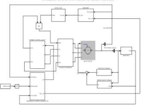
[image:2.612.182.429.533.718.2]Driving circuit consists of Reference Current Generator, PID controller, PWM current controller and MOSFET based three phase Power Converter. Fig. 2 shows the complete Simulink model of three phase BLDC motor with its controlling and driving circuitry. The detailed description of the major blocks of BLDC motor is mentioned below.
© 2019, IRJET | Impact Factor value: 7.34 | ISO 9001:2008 Certified Journal | Page 2057
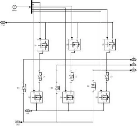
[image:3.612.207.442.109.327.2]Driving circuitry consists of three phase power convertors as shown in Fig. 3, which utilize six power transistors to energize two BLDC motor phases concurrently. The rotor position, which determines the switching sequence of the MOSFET transistors, is detected by means of 3 Hall sensors mounted on the stator.
Fig. 3. Three phase Power Convertor
By using Hall sensor information and the sign of reference current (produced by Reference current generator), Decoder block generates signal vector of back EMF. The basic idea of running motor in opposite direction is by giving opposite current.
In Reference current generator block as shown in Fig. 4, PID controller attempts to minimize the difference between desired angle and the actual measured angle by taking a corrective action to generate reference current signal. Direction of rotation is based on the sign of that reference current.
Fig. 4. Reference Current Generator Block
In current control block shown in Fig. 4, the reference current from current generator is transformed to reference voltage
signal by using Ohm’s law (Vref= IrefR) . This reference voltage is then compared with the measured voltage across control
resistance Rc, where Rc=0.01Ω..When the measured
voltage is less than the reference voltage, control signal is set to one for t = 2Ts, where Ts is sampling time. In other case
[image:3.612.189.422.446.563.2]© 2019, IRJET | Impact Factor value: 7.34 | ISO 9001:2008 Certified Journal | Page 2058
Fig. 4. Current Control Block
Fig. 5. Step response
III. DESIGN OF FUZZY LOGIC SPEED CONTROLLER
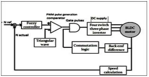
The generated signals are processed by the fuzzy controller and PWM signals for the gate driver circuit is generated by the fuzzy control system. The fuzzy controller has four components- fuzzification, fuzzy rule-base, fuzzy inference engine and defuzzification. Fig. 4 shows the building blocks of a fuzzy logic controller based speed controller. Error (e) andchange in error (Δce) are input linguistic variables and change in duty cycle (Δdc) is the output linguistic variable. Error is the difference between the reference speed and actual speed while change in error is the difference between the present error
and previous error. Output (Δdc) could be positive or negative and added with the existing duty-cycle to determine the new
duty-cycle. Fuzzy logic uses linguistic variables instead of numerical variables. The method of converting numerical variables to linguistic variables is called fuzzification. Fuzzy logic linguistic terms are mostly expressed in the form of logical implications, such as If-Then rules. These rules describe a range of values known as fuzzy membership functions. Fuzzy membership functions may be in the form of a triangle, a trapezoid or a bell.
Initially, motor is operated in 120 degree conduction mode to get adequate back EMF magnitude. In open loop mode, Pulse Width Modulation (PWM) pulses are produced by comparing carrier signal with duty ratio command. These PWM pulses are logically AND with the switching pulses generated and used to trigger the inverter switches. In closed loop control, PWM signals are generated from the fuzzy controller output value. This value is considered as the reference for PWM generation. The input to the fuzzy controller is the error between the reference speed and actual speed. Fig. 4 shows the block diagram of closed loop control of BLDC motor drive using fuzzy logic controller. Fuzzy Associative Memory (FAM) is shown in Table 3.
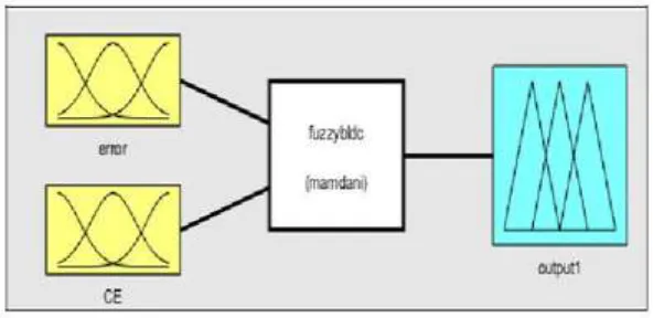
[image:4.612.197.428.74.356.2]The FLC isdesigned using MATLAB-FIS Editor as shown in Fig. 5.
[image:4.612.191.430.610.733.2]© 2019, IRJET | Impact Factor value: 7.34 | ISO 9001:2008 Certified Journal | Page 2059
Fig. 7. FIS editor for speed control of BLDC motor
The simulation of the proposed system was implemented using MATLAB software and the corresponding results and waveforms were obtained. The sampling time is 1 second. The main components are BLDC motor, inverter, back EMF difference calculation block and commutation logic block. Fuzzy controller improves settling time and overall performance. In commutation logic block, the commutation signals for inverter are produced from zero crossing of back EMF difference. Switch S1 is triggered at positive going zero crossing point of back EMF difference and trigger signals for other switches are generated. Fig. 9 shows the block of commutation logic. The fuzzy controller is developed in MATLAB-FIS editor as shown in Fig. 8. The inputs to controller are error and change in error as given in Fig. 8. Fuzzy membership function of output and fuzzy rules used in MATLAB/Simulink model are depicted in Fig. 9 and Fig. 10. Voltage delay essential for suitable commutation of inverter switches are achieved by back EMF difference estimation method. The simulation model of the complete BLDC drive system is shown in Fig. 12.
Stator current at reference speed of 3500rpm with a load of 1Nm at 1sec simulation time is shown in Fig. 12. The model shape for stator current is quasi square waveform. In 120 degree conduction mode, one switch conducts for 120 degree but pair of switches in different legs conducts for 60 degree and hence, stator current is not quasi square.
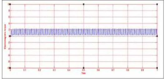
[image:5.612.179.436.499.596.2]Back EMF and current at reference speed of 3500rpm is given in Fig. 13 with phase commutation occurring at desired position. The speed response is shown in Fig. 14 where actual speed tracks the reference speed. The torque output is given in Fig. 15. The machine caters to reference speed even when BLDC motor is loaded. MATLAB Simulink model of sensorless three phase BLDC motor fed from four switch inverter was developed with a fuzzy logic speed controller for better performance of the drive. Its speed and torque responses are satisfactory and optimum. From the simulation results, it is inferred that sensorless technique using back EMF difference gives good response and can be implemented using high performance controllers without any filters.
© 2019, IRJET | Impact Factor value: 7.34 | ISO 9001:2008 Certified Journal | Page 2060
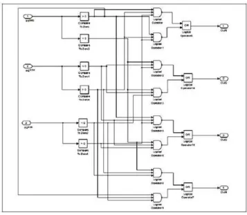
[image:6.612.133.490.56.367.2]Fig. 9. Commutation logic implemented in MATLAB Simulink model
Fig. 10. Fuzzy membership functions of error and change in erro
[image:6.612.174.439.397.503.2]© 2019, IRJET | Impact Factor value: 7.34 | ISO 9001:2008 Certified Journal | Page 2061
Fig. 12. MATLAB simulation model of proposed BLDC drive system
[image:7.612.174.434.405.692.2]Fig. 13. Stator back EMF simulation waveforms
© 2019, IRJET | Impact Factor value: 7.34 | ISO 9001:2008 Certified Journal | Page 2062
[image:8.612.170.434.63.190.2]
Fig. 15. Torque output simulation waveform
IV. HARDWARE IMPLEMENTATION
The control algorithm for proposed BLDC drive system is developed using C2000 Piccolo microcontroller. The C2000 piccolo launch pad, LAUNCHXL-F28027 is a low cost board from Texas Instruments Piccolo F28027x devices that allows direct USB interface of board with PC and TMS320F2807 microcontroller platform is used for closed loop control of BLDC motor. Voltage regulator IC 7805 and IC 7812 are DCregulated ICs of output voltages 5V and 12V respectively. Gate pulses generated microcontroller are 5V and insufficient to trigger a power MOSFET and gate drive voltage of the MOSFET has a range of 12 to
15V. Thus, an 8 pin IC TLP250 is used for amplification and isolation. ST80N55 power MOSFETs owing to their
high density, low on resistance, dv/dt capability are used for inverter circuit.
C/C++ code was generated using embedded coder, MATLAB coder and Simulink coder with the support of Texas Instruments code composer studio V5. The hardware circuit is shown in Fig. 16. A 20 V DC input supplies the four switch inverter and voltage regulators. This voltage is stepped down to 12V with voltage regulator IC 7812 and given to gate driver TLP250.
Voltage regulator IC 7805 supplies 5V to microcontroller. The commutation order for four switches is detected and
duty cycle of PWM pulses is governed by speed controller output. The signals are generated and speed is
determined using C2000 microcontroller to maintain BLDC motor within safe operating limits. PCB circuit comprises of four
switch inverter, two capacitors, voltage regulators, gate driver circuits, protection circuits and C2000 piccolo
microcontroller. Motor speed is determined by microcontroller and transmitted from the target using SCI module of C2000. The waveform transmitted is acknowledged by the host PC using SCI receiver pins of C2000 and observed in the host PC.
© 2019, IRJET | Impact Factor value: 7.34 | ISO 9001:2008 Certified Journal | Page 2063
[image:9.612.174.438.82.296.2][image:9.612.188.425.322.666.2]
Fig. 16. Hardware implementation of proposed BLDC motor drive
Fig. 17. Speed output waveform
© 2019, IRJET | Impact Factor value: 7.34 | ISO 9001:2008 Certified Journal | Page 2064
Fig. 19. PWM signals to inverter switches
V. CONCLUSIONS
In this paper, modeling of three phase BLDC motor and its optimized PID position control . Comparative study is carried out in which the response of fuzzy logy based controller is compared with the PID controller designed using ZN method
The simulation results that the controller performance with fuzzy logy with the ZN method. Fuzzy logic controller is employed for closed loop speed control. Sensorless method increases reliability and simulation was done using MATLAB. Hardware was implemented using C2000 microcontroller. The proposed drive is simple, reliable and easy to implement as it eliminates complex delay circuit. There is no need of taking motor neutral potential and hence the problem of common mode noise is reduced as there is no neutral potential required.
REFERENCES
[1] N. Hemati, J. S. Thorp, and M. C. Leu, “Robust nonlinear control of Brushless dc motors for direct-drive robotic
applications,” IEEE Trans. Ind. Electron., vol. 37, pp. 460–468, Dec 1990.
[2] P. M. Pelczewski and U. H. Kunz, “The optimal control of a constrained drive system with brushless dc motor,” IEEE Trans.
Ind. Electron., vol. 37, pp. 342–348, Oct. 1990.
[3] K. Ang, G. Chong, and Y. Li, “PID control system analysis, design, and technology,” IEEE Trans.Control System Technology,
vol. 13, pp. 559-576, July 2005.
[4] T. O..Mahony, C J Downing and K Fatla, “Genetic Algorithm for PID Parameter Optimization: Minimizing Error Criteria”,
Process Control and Instrumentation 26-28 July 2000, University of Stracthclyde, pg 148- 153.
[5] M .S. Aspalli, Farhat Mubeen Munshi, Savitri.L.Medegar, “Speed control of BLDC Motor with Four Switch Three Phase
Inverter using Digital signal Controller,” International Conference on Power and Advanced Control Engineering (ICPACE), 2015.
[6] M. Shanmugapriya, Prawin Angel Michael, “Sensorless Control of an Four Switch Three Phase Inverter using FPGA,” IEEE -
International Conference On Advances In Engineering, Science And Management (ICAESM -2012), March 30-31, 2012.
[7] J.-H. Lee, S.-C. Ahn, and D.-S. Hyun,“A BLDCM drive with trapezoidal back EMF using four-switch three phase inverter,” in
Conf. Rec. IEEE IAS Annu. Meeting, vol. 3, pp. 1705–1709, 2000.
[8] G. J. Su and W. McKeever, “Low-cost sensorless control of brushless DC motors with improved speed range,” IEEE Trans.
Power Electron., vol. 19, no. 2, pp. 296–302, Mar. 2004.