Analysis of Cavity Tool Stresses in Channel Angular Extrusion
R. Lupoi
1, aand F.H. Osman
1, b1 Department of Mechanical Engineering, University of Bath,
Claverton Down, BA2 7AY, Bath, United Kingdom.
a [email protected], b [email protected]
Keywords: ECAE, Stress analysis, Pressure distribution, Numerical Analysis, Energy absorption.
Abstract. The Channel Angular Extrusion (CAE) technique is a process, in which a deformable solid material is led to yielding through the intersection of inclined channels. Compared to classic plastic deformation, the process is technically simple but the material experiences, instantly, large plastic deformation. The deformation occurs locally and high internal stresses develop during the process. In most cases the process is used for grain size refinement. Equal Channel Angular Extrusion (ECAE) is a special case where the intersecting channels are of equal cross sections. In this paper, an analytical study of the internal stresses and those developed along CAE tools is presented. A deformation model is introduced for the general process of channel extrusion in which the intersecting channels are not necessarily equal. The procedure splits the material at the intersection of the channels into two zones; one causes the deformation while the other remains rigid. The analysis is also applied to the particular case of ECAE, and the results are compared with those obtained from a finite element analysis and the overall experimental pressure.
Introduction
The first delivery of most materials is in its softest state so that it could be shaped easily by metal removal or through plastic deformation. Improved mechanical properties usually result from the imposition of strains on metallic materials that cause grain deformation. In order to add homogeneity in the distribution and size of grains the material is subsequently heat treated. When large strains are required, the mechanism for the evolution of small grains is complex, and therefore multiple reductions that employed through traditional forming processes become impractical.
extrusion pressure, an experimental set-up [6], with sliding die walls, was used in order to reduce friction and wear.
New and novel uses of this method seem to require better understanding of the mechanism of deformation and the stress system that evolves in the process. The use of ECAE was extended into other spheres by Osman [7], where it was exploited and formulated to provide a new technical concept for energy dissipation. Deformation through equal channels was realised in the form of a Universal Re-useable Energy Absorption Device(UREAD). Such a new technology appears to have wide domains of application, in parallel with the structural refinement of metallic materials. Most of the research carried out in this area has been on the process of imposing large strains on metallic materials. The Channel Angular Extrusion(CAE) process, in most cases, is asymmetric where localised plastic deformation is dominant, hence the study of the forming stresses, tool forces, energy dissipation and the mechanism of local deformation is important in order to assess the technical capabilities of the process.
In this paper, an analytical approach to predict tool stresses and cavity stresses for the general CAE process is presented and results applied to ECAE and compared with those from other techniques.
Stress-zone model for CAE
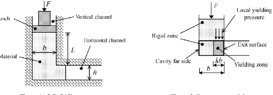
Fig.1 shows a two-dimensional schematic diagram of the 90 degree single CAE process with its dimensional properties and parts. The material is forced to deform from the vertical channel into the horizontal channel through widths b and h respectively. The length of the deformable material,
L, remaining in the vertical channel is important when considering the force required to cause the deformation, F.
Figure 1. 2-D CAE process Figure 2. Stress-zone model
[image:2.595.71.528.418.578.2]
h L
k for 0Lh (1)
k=1 for Lh (2)
Stress analysis
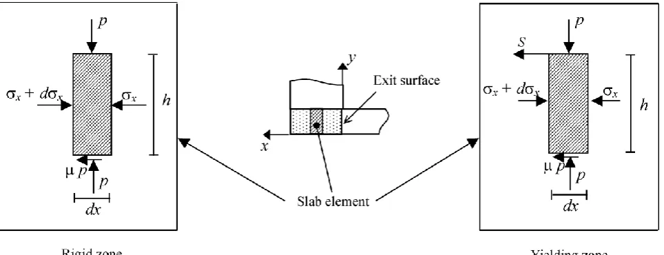
The stress-zone model, shown in Fig. 2, provides the basis of elemental analysis in the yielding and rigid zones inside the intersection volume between the channels. Fig. 3 shows a slab element,
dx, that is located at a distance x from the exit surface, the stress system for both zones is also shown. Normal stress components of σx act on the vertical surfaces while a vertical pressure, p,
[image:3.595.60.542.297.482.2]exists on the horizontal surface, in addition to the frictional drag, µp, when the material is in contact with tool surfaces. Also, a resistant force, S, exists and acts between the rigid zone in the vertical channel and the yielding zone. However, its effect on the rigid zone in the intersection volume is negligible.
Figure 3. Stress system in the intersection zone
Applying force equilibrium in the horizontal direction, x, Eq. 3 and Eq. 4 are obtained for the yielding and rigid zones respectively, taking into consideration the interface surface at kb. Also, the traditional assumptions are applied; that the material being isotropic, homogeneous and incompressible, and inertia forces are negligible [8].
(xdx)hSpdxxh0 [0 xkb] (3)
(x dx)hpdxxh0 [kb xb] (4)
In the slab analysis [8], friction exists only at the boundary and has very little influence on the direction of the principal stresses. In addition, the material is constrained to flow between two parallel surfaces and therefore the principal stress directions are horizontal and vertical inside the deforming volume of the yielding zone. Applying Tresca yield condition, ( p-σx=2k ) with k as
the material yield shear stress gives;
dx dp (5)
between the slab element and the rigid volume in the vertical channel and may be written as, τk dx.
Substituting Eq. 5 into Eq. 3 and Eq. 4, integrating both equations and satisfying the boundary conditions give the vertical pressure distribution on the surface of the intersection with the rigid zone in the vertical channel;
[0 xkb] (6)
[kbxb] (7)
The average vertical pressure pave in the intersection volume is obtained from Eq. 6 and Eq. 7 and
expressed in terms of the material yield stress as follow;
(8)
where
2 1 ) 2 1 ( 2
1 kbh
e (9)
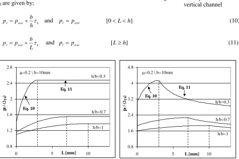
For the case of ECAE, the width of the vertical channel, b, becomes equal to the width of the horizontal channel, h. Fig. 4 gives results for an ECAE process when b=h=10 mm. The coefficient of friction, is taken as 0.2 and the results are presented for different values of L and k. The distribution shows increasing stress values from the exit surface, x=0, to the cavity far side,
x=b. Also, the stress level rises as the rigid volume in the vertical channel increases, until the limiting condition when L is equal to h or k=1.
Figure 4. ECAE vertical stress distribution(10x10) Figure 5. Comparison with numerical analysis(10x5)
In order to simulate the initial yielding conditions, ECAE Experiments (10x10mm) were carried out using Lead billets to a displacement of 1mm. Billets were lubricated before each use and the material compressive yield stress measured 11MPa. The billet rigid zone in the vertical channel, L, was 5mm (k=0.5). The experimental average relative pressure is superimposed on the analytical results shown in Fig. 4. The analytical results of the vertical stress distribution, for the case of unequal channels, b=10mm and h=5mm are shown in Fig. 5. When compared with those of Fig. 4,
2 1 ) 2 1 ( 2 1
2
h x k e p k p
2
2 1 ) 2 1 ( 2
1 kbh
e h kb x e ) ( 1 2 1 2 2 1 2 ) ( h kb b h bk k ave e h b k e b h
p
they indicate significant increase in the acting pressure when the width of the exit channel is halved. Fig. 5 also includes the results of a numerical analysis using the finite element analysis package; ANSYS. Both solutions seem to follow similar trends and values compare favourably.
Stresses on the vertical channel
The forces acting on the rigid zone in the vertical channel, under frictionless conditions are shown in Fig. 6. The average pressure, pave, delivered by the punch and given by Eq. 8 is
superimposed as a hydrostatic component on all sides of the rigid zone. The effect of the material deforming into the horizontal channel, Ft, is likely to be absorbed by the side wall
that is in-line with the exit surface. However, the forces and pressures acting on the right and left hand side walls of the vertical channel are (Fr , pr ) and (Fl , pl ) respectively. pr and
pl are given by;
r ave k
h b p
p and pl pave [0Lh] (10)
r ave k
L b p
p and pl pave [Lh] (11)
Figure 7. Pressure on the left hand side wall Figure 8. Pressure on the right hand side wall
Fig. 7 and Fig. 8 give the average side pressure on the vertical channel left and right hand sides respectively. The results are shown for different values of L and the ratio h/b. The results suggest an increase in pressure on both sides until L is equal to h. For higher values of L the pressure on the left hand side wall remains constant, while it decreases on the right hand side wall. For L=0 the pressure should instantly drop to zero.
Fig. 9 shows the pressure distribution on the tools obtained by the Finite Element Analysis as implemented by ANSYS. The widths of the vertical and horizontal channels were 10mm and 5mm respectively and simulating Lead with a friction coefficient of 0.2. The results show that the right hand side wall experienced higher stresses than that of the left hand side wall. Also, it is noticed that the maximum predicted stresses are at the lower section of the right hand side wall. Such results are comparable to other ECAE investigations[9].
F=pav eb
Ft=kbk
Fl=paveL Fr=paveL+ kbk
b F=paveb
[image:5.595.63.537.293.608.2]L
Figure 6. Force equilibrium on vertical channel
0.8 1.2 1.6 2 2.4 2.8
0 5 L [mm] 10
p
l
/ (
2
k
)
h/b=0.3
h/b=0.7
h/b=1 =0.2 \ b=10mm
Eq. 10
Eq. 11
0.8 1.6 2.4 3.2 4 4.8
0 5 L [mm] 10
p
r
/ (
2
k
)
h/b=0.3
h/b=0.7
h/b=1 =0.2 \ b=10mm
Eq. 10
Figure 9. Tool stresses from a Finite Element Analysis
Conclusions
The Channel Angular Extrusion has been investigated and an analytical solution for tool stress was presented. A deformation pattern was introduced and applied also to the special case of Equal Channels Angular Extrusion (ECAE). The billet length and its effect on tool stresses were investigated and the predictions showed that tool stresses vary with the length of the rigid portion of the billet. The analysis also showed that the tool wall near the exit surface experienced higher stresses that at the far end supportive wall. Finite element numerical analysis and experimental results compared favourably with the current analysis.
References
[1] V.M. Segal, “Materials processing by simple shear”, Materials Science and Engineering A, 197 (1995), 157-164.
[2] V.M. Segal, K.T. Hartwig, R.E. Goforth, “In situ composites processed by simple shear”,
Materials Science and EngineeringA, 224 (1997), 107-115.
[3] V.M. Segal, “Equal channel angular extrusion: from macromechanics to structure formation”,
Materials Science and EngineeringA, 271 (1999), 322-333.
[4] Zubear Ahmed Khan, Uday Chakkingal, P. Venugopal, “Analysis of forming loads, microstructure, development and mechanical property evolution during equal channel angular extrusion of a commercial grade aluminum alloy”, Jour. of Mat. Proc. Tech., 135 (2003), 59-67.
[5] A. Rosochowski, L.Olejnik, M.Richert, “3D-ECAP of square aluminum billets”, proceedings of the 8th
ESAFORM conference, (2005).
[6] Aidan Shan, In-Ge Moon, Jong-Woo Park, “Estimation of friction during equal channel angular (ECA) pressing of aluminum alloy”, Jour. of Mat. Proc. Tech., 122 (2002), 255-259.
[7] Fayek Osman, “Reusable Energy Dissipation Device”, Patent, W0 2004/044450 A1, 2004.
[8] R. Hill, “The mathematical theory of plasticity”, Clarendon Press, 1985.