Static Synchronous Series Compensator and Fuzzy
Logic based Power Flow Control and Stability
Improvement in Photovoltaic Power Plant
Infinite-Bus System
M. Chandramoorthy1, C. Dhineshkumar21, 2
Department of Power System Engineering, Arulmigu Meenakshi Amman College of Engineering
Abstract: This paper presents the stability improvement and power-flow control results of photovoltaic Power Plant using a static synchronous series compensator (SSSC). Photovoltaic System (PV system) intended for the supply of trade power into the electricity grid. They are discerned from most building-mounted and other decentralized solar power applications because they supply power at the utility level, rather than to a local user or users. An Oscillation Damping Controller (ODC) of the proposed SSSC for using stability control. A frequency-domain approach based on a linearized system using eigen value analysis is accomplished. A time-domain scheme based on a nonlinear system model subject to a disturbance is also performed.
Keywords: SSSC, PV System, ODC, Linearized System
I. INTRODUCTION
The design, modelling and control design of a 48-step inverter based static synchronous series compensator (SSSC) is presented and a magnetic circuit is chosen which contains eighteen single-phase three winding transformers and six single-phase two winding transformers to add the output voltages of eight three-phase inverters. An equivalent circuit model of the SSSC is derived and based on this model a proportional-plus-integral controller is proposed. The controller gains are chosen through eigen value analysis of the IEEE first benchmark model for subsynchronous resonance (SSR) analysis. The SSSC model, its control and the results of the eigen value analysis are then legalised through PSCAD/EMTDC simulation. It is shown that for certain controller gains torque amplification of the shaft modes can occur [1].
A review with a concise report and analysis of the fundamentals, characteristics, analytical details, merits, and problems associated with existing methods in frequency and time domain for harmonic analysis in practical power networks. The explanation and analysis are centred on methods industrialized in the harmonic domain, hybrid frequency-time domain, and time domain, respectively [16]. A bridged dynamic equivalent model of WFs based on the spanning tree (ST) is proposed. First, the clustering method grounded on the growing ST is first applied to the dynamic equivalent of WFs. Second, according to the mathematical model of doubly fed induction generator (DFIG)and the Permanent Magnetic Synchronous Generator (PMSG), clustering variables of DFIG and PMSG are classified into internal variables and external variables, reflecting the dynamic characteristics of WTs [8].
thereby emulating an inductive or a capacitive reactance in series with the transmission line. The emulated variable reactance, inserted by the injected voltage source, inspirations the electric power flow in the transmission line [19].
II. METHODOLOGY
A. PV system using SSSC
In the Existing system presents the stability improvement and power-flow control results of a DFIG-based offshore wind farm (OWF) connected to a one-machine infinite-bus (OMIB) system using a static synchronous series compensator (SSSC). An oscillation damping controller (ODC) of the proposed SSSC is designed by using modal control theory to render proper damping to the dominant mode of the studied synchronous generator (SG). A frequency-domain approach based on a linearized system model using eigen value analysis is accomplished. A time-domain scheme based on a nonlinear system model subject to a disturbance is also performed. It can be concluded from the simulation results that the proposed SSSC joined with the designed ODC can effectively improve the stability of the studied OMIB system with an OWF under various disturbances. The inherent low-frequency oscillations of the OMIB system can also be effectively suppressed by the proposed control scheme.
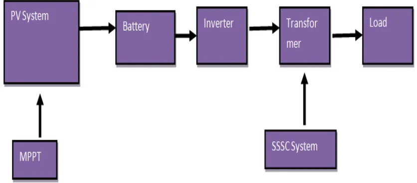
[image:2.612.93.511.415.599.2]This paper has proposed the stability-improvement and power-flow control results of PV System using a static series compensator (SSSC). The proposed SSSC has been properly connected in series with one of the two parallel lines to supply adequate reactive power. A PI-type ODC has been designed for the proposed SSSC by using a unified approach based on modal control theory to assign the mechanical mode of the studied SSSC system on the desired locations of the complex plane. Root-loci plots under various operating conditions and time-domain simulations of the studied SSSC system subject to a three-phase short-circuit fault at the infinite bus have been systematically performed to demonstrate the effectiveness of the proposed SSSC joined with the designed PI ODC on damping inherent low-frequency oscillations of the studied SSSC system and improving system stability under different operating conditions. It can be concluded from the simulation results that the proposed SSSC joined with the designed PV has the ability to improve the performance of the studied SSSC plus the PV system under different operating conditions as shown in Figure 1. The designed ODC of the proposed SSSC can also effectively stabilize the studied system under an unstable scenario.
Figure 1 Block Diagram of the PV system using of SSSC
B. System Configuration and Models
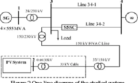
The employed capacity of the proposed SSSC is 134 MVA, and it is calculated by taking 3 times (three-phase power) the multiplication of the maximum current through Line 34-2 and the maximum voltage injected by the SSSC. The employed mathematical models of the studied system are described as below.
Figure 2 One-line diagram of the studied system.
III. SIMULATIONRESULTS
[image:3.612.155.450.393.723.2]The details of the test system are given in appendix-1. It is a three area four bus system. Two parallel lines are connected between the two areas with 200 and 280km in length. The SSSC is connected in the second line of 280km in length. The line is divided into two parts of 100km and 180km. SSSC is connected between bus 1 and bus 2 in the 100 km length line. The simulation carried out is as follows: Initially, power flow control of the line is tested. Hence, the real power reference is varied and the results are discussed. Qref is kept constant. SSSC is connected at 0.01sec. Before the insertion of SSSC, the real power flow through the line is 8.85 pu. In case (a) the Pref is set to 8.5 pu and at 0.25 sec, Pref is increased to 10 pu. Figure 3.18 shows the corresponding waveforms for power flow through transmission line 2. It is clear from the figure that the commanded power references are achieved. In case (b) the Pref is increased to a higher value of 13 pu. But the final power flow achieved is 12.8 pu which is shown in Figure 3.
Figure 3 Real power flow through line 2 for case (a)
[image:3.612.156.452.404.548.2]The next command is given to Qref. Pref is fixed to a value of 11pu. Before the insertion of SSSC, the reactive power flow is -0.62 pu. Qref is initially commanded to -0.5 pu and at 0.25 sec it is changed to -0.8 pu. The figure 4 shows the corresponding waveform for set values are obtained finally.
Figure 5 shows the quadrature relationship between the line current and the injected voltage. To have a clear waveform, the magnitude of the line current is reduced to 0.25 of the original value.
Figure 5 Wave forms for 0.25 of line current and injected voltage
[image:4.612.151.457.144.289.2]For analyzing transient stability, a three phase to ground fault is simulated at 0.2 sec in line 2. The fault is cleared at 0.3 sec. The reference real and reactive power values set are 11 pu and -0.67 pu respectively and the results are analyzed. The figure 6 and 7 show the real and reactive power flow through transmission line 2.
Figure 6 Real power flow through line 2
[image:4.612.125.478.357.705.2]Figure 8 Current flowing through line 2
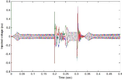
Figure 8 represents the current flow through line 2 and the value is 10 pu during normal operating condition and the peak value goes to 147 pu during fault. Figure 9 shows the injected voltage from SSSC and it is 0.06 pu during steady state condition and the oscillations are more during fault period.
Figure 9 Injected voltage from SSSC
IV.CONCLUSIONS
REFERENCES
[1] L. S. Kumar and A. Ghosh, “Modeling and control design of a static synchronous series compensator,” IEEE Trans. Power Del., vol. 14, no. 4, pp. 1448–1453, Oct. 1999.
[2] M. S. Castro, H. M. Ayres, V. F. da-Costa, and L. C. P. da-Silva, “Impacts of the SSSC control modes on small-signal and transient stability of a power system,” Elect. Power Syst. Res., vol. 77, no. 1, pp. 1–9, Jan. 2007.
[3] G. Radman and R. S. Raje, “Dynamic model for power system with multiple FACTS controllers,” Elect. Power Syst. Res., vol. 78, no. 3, pp. 361–371, Mar. 2008.
[4] J. Guo, M. L. Crow, and J. Sarangapani, “An improved UPFC control for oscillation damping,” IEEE Trans. Power Syst., vol. 24, no. 1, pp. 288–296, Feb. 2009.
[5] A. Rajabi-Ghahnavieh, M. Fotuhi-Firuzabad, M. Shahidehpour, and R. Feuillet, “UPFC for enhancing power system reliability,” IEEE Trans. Power Del., vol. 25, no. 4, pp. 2881–2890, Oct. 2010.
[6] P. Kundur, Power System Stability and Control. New York: McGraw-Hill, 1994. [17] CIGRE, Modeling New Forms of Generation and Storage TF.01.10, Fifth draft, Jun. 2000.
[7] P. C. Krause, Analysis of Electric Machinery. New York: McGrawHill, 1987.
[8] D. J. Trudnowski, A. Gentile, J. M. Khan, and E. M. Petritz, “Fixedspeed wind-generator and wind-park modeling for transient stability studies,” IEEE Trans. Power Syst., vol. 19, no. 4, pp. 1911–1917, Nov. 2004.
[9] S. M. Muyeen, M. H. Ali, R. Takahashi, T. Murata, J. Tamura, Y. Tomaki, A. Sakahara, and E. Sasano, “Transient stability analysis of wind generator system with the consideration of multi-mass shaft model,” in Proc. Int. Conf. Power Electronics and Drives Systems, Jan. 16–18, 2006, vol. 1, pp. 511–516.
[10] P. Cartwright, L. Holdsworth, J. B. Ekanayake, and N. Jenkins, “Coordinated voltage control strategy for a doubly-fed induction generator (DFIG)-based wind farm,” in IEE Proc.-Gener. Transm. Distrib., Jul. 2004, vol. 151, no. 4, pp. 495–502.
[11] L. Yang, G. Y. Yang, Z. Xu, Z. Y. Dong, K. P. Wong, and X. Ma, “Optimal controller design of a doubly-fed induction generator wind turbine system for small signal stability enhancement,” IET Generat., Trans., Distribut., vol. 4, no. 5, pp. 579–597, May 2010.
[12] B. C. Pal and F. Mei, “Modelling adequacy of the doubly fed induction generator for small-signal stability studies in power systems,” IET Renew. Power Generat., vol. 2, no. 3, pp. 181–190, Sep. 2008.
[13] L. Fan, R. Kavasseri, Z. L. Miao, and C. Zhu, “Modeling of DFIGbased wind farms for SSR analysis,” IEEE Trans. Power Del., vol. 25, no. 4, pp. 2073–2082, Oct. 2010.
[14] F. Wu, X.-P. Zhang, K. Godfrey, and P. Ju, “Small signal stability analysis and optimal control of a wind turbine with doubly fed induction generator,” IET Generat., Trans., Distribut., vol. 1, no. 5, pp. 751–760, Sep. 2007.
[15] S. Panda, N. P. Padhy, and R. N. Patel, “Power-system stability improvement by PSO optimized SSSC-based damping controller,” Electric Power Compon. Syst., vol. 13, no. 5, pp. 468–490, 2008.
[16] A. C. Pradhan and P. W. Lehn, “Frequency-domain analysis of the static synchronous series compensator,” IEEE Trans. Power Del., vol. 21, no. 1, pp. 440– 449, Jan. 2006.
[17] G. N. Pillai, A. Ghosh, and A. Joshi, “Torsional oscillation studies in an SSSC compensated power system,” Elect. Power Syst. Res., vol. 55, no. 1, pp. 57–64, Jul. 2000.
[18] K. A. Padiyar, FACTS Controllers in Power Transmission and Distribution. New Delhi: New Age, 2007.
[19] K. K. Sen and M. L. Sen, Introduction to FACTS Controllers: Theory, Modeling, and Applications. Hoboken, NJ: Wiley, 2007.