Designing Vivaldi Antenna with Various Sizes
using CST Software
NORHAYATI HAMZAH, KAMA AZURA OTHMAN
Abstract :- This paper will summarized the different size of opening width and length of the slot flare Vivaldi Antenna. The different size of opening width and length will bring effects on the VSWR and S11. The Vivaldi Antenna is designed to cover from 2 to 18 GHz by using the CST Microwave Studio Software. Then these antennas are constructed using RT/Duroid 5870 which have dielectric constant r 2.33. Thickness and copper is 0.508mm and 0.035mm respectively. Index Terms - EM (Electromagnetic), Vivaldi Antenna Aerial
I. INTRODUCTION
In 1979, Gibson proposed a tapered slot antenna also known as a Vivaldi Antenna [1]. Vivaldi antenna is the present invention relates to improvement in antennas. In particular the present invention relates to broadband of the Vivaldi, notch or tapered slot antenna family. The exponential flare shape was originally adapted to requirement for a constant beamwidth antenna which could cover the microwave frequency range between 2 GHz and 20 GHz.
In operation, the antenna radiates preferentially from the open end of the notch in a direction away from the notch and along the axis of symmetry. The antenna may thus be classed as an end-fire antenna [2].
In theory, tapered slot antennas generally have wide bandwidth, high directivity and are able to produce symmetrical radiation pattern. It also simple feed structure, and easy for fabrication. This type of antenna has been applied to satellite communications, remote sensing, and radio telescope. The advantages of endfire tapered slot antennas include producing a symmetrical beam in the E-and H-plane or changing beamwitdh by varying the shape, length, dielectric thickness and dielectric constant of the tapered slot antenna [7].
Any conventional tapered slot antenna were constructed by conventional microwave lithographic thin film technique on substrate that having a high dielectric constant for example alumina [2]. The original Vivaldi antennas were tapered notch antenna having notches which open in an exponential flare shape.
Manuscript received January 11, 2011; revised February 09, 2011. Norhayati Hamzah is with the Faculty of Electrical Engineering, Universiti Teknologi MARA, 40450 Shah Alam, Selangor Darul Ehsan Malaysia (phone: 6012-334-7350; fax: 603-554-43740; e-mail: [email protected]).
Kama Azura Othman is with the Faculty of Electrical Engineering, Universiti Teknologi MARA, 40450 Shah Alam, Selangor Darul Ehsan Malaysia (phone: 6012-373-6499; fax: 603-554-43740; e-mail: [email protected]).
A notch is formed in the conductive layer and the gap between the sides of the slot widens from minimum at closed end of the slot to a maximum at the open end. The closed end of the notch line may be fed by any one of a variety of transmission line including microstrip lines, stripline, fin lines and probes.In conventional Vivaldi antennas, the gap is mirror symmetrical about an axis through the centre of the slot and each side has the conductive layer flares. The flared slot is an effective radiating element. On the reverse side of substrate there are formed a ground plane of conductor which acts as the return conductor as shown in Fig.1.
Fig.1 Architecture of Vivaldi Antenna
II.METHODOLOGY
A. Designing Antenna
Vivaldi antenna is designed to radiate at 2 to 18 GHz. Fig.2 illustrate the layout of a construction Vivaldi antenna by using CST Microwave Studio. This antenna consists of single layer. Upper layer is copper layer which has a thickness 0.035 mm. The other side of the microstrip is a ground plane. In this design, the microstrip line is used as a transmission line that is located at the closed end notch. The length and width in this design is 55 mm x 40 mm.
B. Calculation
In theory, the maximum opening width [7] is:
𝑔 = c
𝑓 min εr
where,
c = speed of light (3 x 10⁸) fmin = frequency minimum (2G)
r = dielectric constant (2.33)
Thus,
g = 3×10⁸ 2G × 2.33
= 98.27 mm So,
W max = g/2
= 98.27 mm / 2
= 49.13 mm
Then, the minimum of opening width is:
W min = C f εr
where,
f = center frequency (10G)
W min= 3×10⁸
10G × 2.33
= 19.65 mm
[image:2.595.318.534.128.264.2]Therefore, six different sizes of opening width and length have been developed. The characteristic for each size of antennas is described in Table 1.
Table 1
Size of opening width and length of antenna
C. CST Microwave Studio
These designs were simulated by using CST software to determine the characteristic of the designed antenna. Simulations were done to estimate the values of S11 and VSWR for all type of designs.
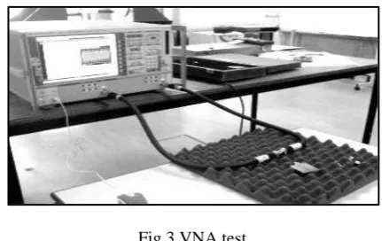
D. VNA (Vector Network Analyzer) Test
This technique is use to measure the value of SII and VSWR of the fabrication antenna. It can be use to compare the simulated and the fabricated antenna. Fig.3 shows the VNA equipment.
Fig.3 VNA test
E. Antenna Training System (ED-3200A)
[image:2.595.312.540.349.452.2]This technique consists of a transmitter and receiver antenna. It can be used to gain the radiation pattern of the receiving antenna which is the Vivaldi antenna.
Fig.4 Measurement between Horn Antenna and Vivaldi Antenna
III. RESULT
A. Simulation Results
[image:2.595.42.282.522.613.2]Table 2 shows the simulated results. From all the results, type 3 shows the best performance. This is due to type 3 has a lower value of S11 as compared to other designs. Furthermore, the value of VSWR for type 3 is approximately to 1.
Table 2 Simulation result
Types S11 VSWR
Type 1 -23.10 1.150 Type 2 -13.96 1.501 Type 3 -44.53 1.012 Type 4 -15.96 1.379
Type Opening width Opening length
Type 1 30 27
Type 2 30 17
Type 3 35 27
Type 4 35 17
Type 5 40 27
[image:2.595.308.549.658.743.2]Fig.5 The value of S11 for all 6 types design
Fig.6 The value of VSWR for all 6 types design
From the simulation result, it was found that the opening length will give effect on the VSWR. The longer the length of the opening the lower value of VSWR can be generated. The value of S11 gives better results if the opening length is longer. In conclusion, to gain the best result on S11 and VSWR the opening width and length must be in range between the ratios of 1 to 1.5. Next, by increasing the opening width it will give effect on the radiation pattern.
Fig.7 Simulated S11 for type 3
Fig.8 Simulated VSWR for type 3
Fig.9 Farfiled pattern for type 3
Fig.10 Radiation pattern for type 3
Fig.6, 7, 8, and 9 are the results of type 3 design for S11, VSWR and radiation pattern. The directivity and gain of the antenna is 11.09dBi and 10.58dB respectively.
B. Fabrication Result
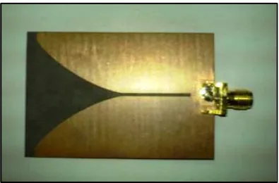
All six different types of Vivaldi antenna were done in simulation. Based on the result obtained from the simulation of antenna design of type 3 was chosen to be fabricated since it gives the most optimum specification.
VSWR = 1.01dB
Fig.11 Fabricated antenna of type 3
[image:4.595.58.280.214.369.2]Fig.12 Experimental S11 of type 3 antenna
Fig.13 Experimental VSWR of type 3 antenna
[image:4.595.47.269.401.550.2]Initially, the S11 and VSWR of a single Vivaldi antenna was measured by using VNA test. Referring to Fig.6, the simulation shows that S11 value is -44.45dB. But in practical experiment (Fig.11), the value is -25.64dB and the center frequency was shifted from 10 GHz to 9.84 GHz. Similarly, the VSWR value showed that the simulated value in Fig.7 is 1.0 at 10 GHz while the value from the experiment is 1.11 in Fig. 12. The center frequency of the antenna of type 3 was shifted 1.6% from the 10 GHz.
Lastly, the results obtain from both simulation and experiment shows that most of the value attained were not exactly similar. This is due to the fact that most equipment has their setting errors. Also, the condition of surrounding must be considered. Not to forget human error such as soldering and during fabrication. Furthermore, the frequency was shifted from the 10 GHz to 9.84 GHz. It may be due to the grounding effects.
IV. CONCLUSION
In this paper, the designs of Vivaldi antenna with various sizes were presented. The simulation and fabrication result of 6 different sizes has been shown. Vivaldi antenna is a wideband antenna. The performance of the antenna meets the desired requirement in term of S11 and VSWR. Vivaldi antenna for 2 to 18 GHz is a wideband antenna produced good directivity and high gain with the suitable opening width and opening length. Also, from the observation the design of the opening width and opening length affects the characteristic of antenna. The application of this antenna can support frequencies between 2 – 18 GHz which is used in radar and military equipment. It also can be applied to satellite communication.
In additional, this antenna can be improved by designing on antipodal Vivaldi antenna and balance antipodal Vivaldi antenna. It is because both of two antennas will become an ultrawide-band antenna with increasing the S11.
REFERENCES
[1] P. J. Gibson, ―The Vivaldi Aerial‖, Proc. 9th Europe Microwave. Conerence., 1979, pp. 101–105.
[2] James Joseph Fisher, ―Vivaldi Antenna,‖ World Intellectual Property Organization, Aug.8,2006.
[3] E. Gazit, ―Improved Design of the Vivaldi Antenna‖, Proc. Inst. Electr. Eng.—H, vol. 135, no. 2, pp. 89–92, Apr. 1988.
[image:4.595.55.283.584.734.2][6] Sang-Gyu Kim and Kai Chang, ―Ultra Wideband Exponentially-Tapered Slot Antenna s‖, Department of Electrical Engineering, Texas A&M University.
[7] Qun Wu*(1), Bo-shi Jin(1), Li Bian(1,2), and Yu-ming Wu(1), Le-Wei Li(1,3), ―An Approach to the Determination of the Phase Center of Vivaldi-based UWB Antenna‖
[8] Kraus, J.D. ―Antennas”, 2nd edition., New York, McGraw-Hill, 1988.
[9] Rainee N. Simons and Richard Q. Lee, ―Characterization of Miniature Millimeter-Wave Vivaldi Antenna for Local Multipoint Distribution Service‖, 49th Automatic RF Techniques Group Conference cosponsored by the Institute of Electrical and Electronics Engineers and the Microwave Theory and Techniques Society, Denver, Colorado, June 13, 1997.
[10] Tuan Anh Vu, Malihe Zarre Dooghabadi, Shanthi Sudalaiyandi, H˚akon A. Hjortland, Øivind Næss, Tor Sverre Lande and Svein Erik Hamran, ―UWB Vivaldi Antenna for Impulse Radio Beamforming‖, Dept. of Informatics, University of Oslo, Norway.