IJEDR1703129
International Journal of Engineering Development and Research (
www.ijedr.org
)
900
Process Line Balancing & Automation by Cellular
Manufacturing Process
1Prof. Ziya Mahmad, 2Prof. Kusekar S. K., 3Prof. Jadhav R. D.
1Assistant Professor Department of Mechanical Engineering, ZCOER, Pune, Maharashtra, India 2Assistant Professor Department of Mechanical Engineering, ZCOER, Pune, Maharashtra, India, 3Assistant Professor Department of Mechanical Engineering, DYPIET,
Ambi Pune, Maharashtra, India
___________________________________________________________________________________________________________ Abstract - The aim of this project is to explore the possible effects on manufacturing by the same traditional way of production in which many problems such as low production, high labor expenditure, poor quality and safety etc. are due to its present method of working in an observed industry (Tuljai Engineering Works) which is situated at pune in Maharashtra. To deal with this present method firstly the study is emphases on line balancing technique. Line balancing is an effective tool to improve shop-floor layout which in turn reduces product cycle time. Cellular manufacturing also has certain advantages like space reduction, higher productivity, improved machine utilization and better quality. Presently the company is facing problems like injury to operators, low productivity, high labor cost, poor quality etc. To cope up with this situation the automation of the whole process is needed. The traditional way of feeding the workpiece in the said Company is done manually with on turning machine. As the workpiece is loaded on machine and held by collet for grooving and chamfering operation which is done simultaneously and it leads to the more disadvantages and expensive with low quality and less safety to the operator. The success of automated assembly in batch or mass production hinges on the effective performance of automated high speed part feeding. In such condition a conventional vibratory bowl feeder for this operation is feasible. This project attempts to make a progress in implementing of a flexible vibratory bowl feeder. The problems incorporated are due to inflexible nature of tool orientation. This project implements the automation with vibratory bowl feeder, collet and pneumatic cylinder. These implemented tools and accessories were focused purely for the purpose of this project only for feeding of a part or workpiece at operational area. The outcome of this project is as the cost plays a vital role in manufacturing which can be reduced by process automation at every station of machine tools which is advantageous in better productivity and quality with more safety.
Keywords: Cellular Manufacturing, Line balancing, Productivity, Vibratory bowl Feeder Mechanism
___________________________________________________________________________________________________________
1. INTRODUCTION
To help maintain a competitive advantage in the global economy, manufacturing companies must continuously strive to increase productivity while reducing the manufacturing cost of their products. This can be tackled in a various ways, e.g. reducing inventory cost, increasing machine utilization and reducing the direct labor cost. If productivity can be improved for instance by reducing the labor content of the process, this should help to reduce the manufacturing cost of their products.
Manufacturing is the backbone of any industrialized nation. Its importance is emphasized by the fact that, as an economic activity, it comprises approximately 20 to 30% of the value of all goods and services produced. A country’s level of manufacturing activity is directly related to its economic health. In general, the higher level of manufacturing activity in a country, the higher the standard of living of its people.
Manufacturing can be defined as the application of mechanical, physical, and chemical processes to modify the geometry, properties and/or appearance of a given starting material in the making of new, finished parts or products. This effort includes all intermediate processes required for the production and integration of a product’s components. The ability to produce this conversion efficiently determines the success of the company. The type of manufacturing performed by a company depends on the types of products it makes. Manufacturing is an important commercial activity carried out by companies that sell products to customers. In the modern sense, manufacturing involves interrelated activities that include product design and documentation, material selection, process planning, production, quality assurance, management, and marketing of products. These activities should be integrated to yield viable and competitive products.
One of these lean practices, cellular manufacturing, is based on a group of different processes located in close proximity to manufacture a group of similar products. The primary purpose of cellular manufacturing is to reduce cycle time and inventories to meet market response times.
Some of the other benefits include:
Space Reduction
Quality Improvement
Labor Cost Reduction
IJEDR1703129
International Journal of Engineering Development and Research (
www.ijedr.org
)
901
Cellular manufacturing is an application of the group technology concepts for factory reconfiguration and shop floor layout design. A part family can be parts similar in size or parts created using similar manufacturing steps. Typically, a cell is dedicated to a single part family.Cellular manufacturing does have some important human resource issues to consider:
Operators must be trained properly to perform tasks including inspection and simple maintenance
Cross functional training is critical since operators perform a variety of tasks and move between workstations and cells as the need arises
Operators should be trained on team building
Supervisors become coaches. Cell teams require only guidance. Supervisors facilitate, assist and guide the overall effort.
Compensation issues: Cell employees usually receive the higher pay because they are better qualified to do multiple tasks. We recommend implementation of an incentive program that provides incentives on the basis of results and incremental improvements.
Management may be concerned that there will be resistance from employees when the result is actually opposite. Typically, any initial resistance disappears once employees understand the win-win situation at hand.
Cells need support from several functions including product engineering, material management, manufacturing engineering, QC/QA, maintenance and management. It is vital to implementation success that this support is committed, visible and consistent.
In order to avoid loading of the work piece on machine manually, we are going to use vibrating bowl feeder to make loading of the work piece automatically. The vibratory bowl feeder is widely used to convey small engineering parts, and can be considered as a typical non-linear dynamic system experiencing repeated impacts with friction. The most important factor to consider when selecting a part feeder is the type of parts to be fed. Bowl sizes and types are determined through a variety of factors such as part size and configuration, part abrasiveness, condition of the part when handled, required feed rate and bowl direction. This report deals with a simplified model and analysis for the dynamic behavior of a single part on the vibrating track of the bowl feeder. The dynamic effects from the variation of several physical parameters are examined and the important features for implementing of the vibratory feeder are presented.
1.1 Overview of the Paper:
Based on literature and by visiting to an industry, it is found that there is requirement for the automation of manufacturing process to reduce labor and production cost, improve quality and productivity along with labors safety. Two methods were identified for process automation: Robotic arm and vibrating bowl feeder. Due to limitations of robotic arm, vibratory bowl feeder was implemented. Process is automated with the help of vibrating feeder, collet and pneumatic cylinder. After implementing this automated process it was found that labor cost is minimized and productivity is improved with better quality and safety.
2. REVIEW ON LITERATURE Brief about the work done so far:
Campain (2014) in his research paper titled “Technological growth and unemployment: A global scenario analysis.” Explored the possible features generated by the development of the artificial intelligence. He focused on social consequences of automation and robotization, with special attention being paid to the problem of unemployment.
Hughes (2014) investigated about technological unemployment. In his paper “Are technological unemployment and basic income guarantee inevitable or desirable” he questioned, if in the future robots take most people’s jobs, how will human beings eat? The answer that has been more or less obvious to most of those who have taken the prospect seriously has been that society’s wealth would need to be re-distributed to support everyone as a citizen’s right.
Metternich et. al. (2013) in their research work starts with investigating existing analytical Methods for measuring work. The different measuring concepts have been applied to the cellular manufacturing reference line at the process learning factory at TU Darmstadt. An adequate evaluation system considering reality, detail, and variation and effort levels has been defined in order to assess the results’ suitability for evaluating manual work in a cellular manufacturing line, pointing out potentials and limits of the individual approaches. As the final outcome, a ranking of different work measurement concepts for the cellular manufacturing reference line is presented, verifying the applicability of the general approach and serving as a basis for further evaluation of other lines.
Apostolos et. al. (2013) have presented critical review on the energy efficiency of important manufacturing processes Relevant conventional and non-conventional processes, utilized in the three major industrial sectors of aeronautics, automotive and white goods are briefly discussed. Information related to their energy efficiency is provided. The conclusions of both the analysis and the discussion comprise some practical aspects and recommendations for the energy efficient use of selected processes.
IJEDR1703129
International Journal of Engineering Development and Research (
www.ijedr.org
)
902
Park et. al. (2012) did the development of the intelligent operation planning system considering machining safety. In this paper, an intelligent operation planning system considering machining safety has been introduced to model the process of selecting cutting conditions and subsequently to arrive at effective and safe cutting. INOPS (Intelligent Operation Planning System) based on such a proposal has been developed for milling processes. INOPS is composed of two main components: (1) the artificial neural networ k to learn cutting conditions, and (2) rules and equations to modify the cutting conditions for safe machining. The main functions of INOPS for prismatic components are briefly described and then discussed.Seifermann et. al. (2012) have stated about cellular manufacturing (CM). Cellular manufacturing have been proven to be an economic, efficient and lean approach bringing flexibility into machining areas. Corresponding solutions use several basic machines that are adapted to the machining task in a right-sized equipment approach. However, the use of basic, low cost machinery providing just necessary functions results in a relatively high manual operation effort. The preferred approach in order to reduce manual work in production is automation. Traditional automation of man-machine systems – especially in western countries tends to be comprehensive and thus often complex and expensive. A low cost, lean automation intelligently being adapted to the individual Task, as well as a decision method for choosing the tasks worth being automated, is required.
Maher (2010) has worked on design and development of automated programmable orientation tools for vibratory bowl feeder. This project attempts to make progress in the development of a flexible VBF, the main problems being the inflexible nature of the orientation tools as currently employed. The project tackles the design, development and manufacture of a range of automated programmable orientation tools which in combination make up a typical orientation system for the VBF. Three prototypes tools were developed: the Wiper Blade, Narrow ledge and Edge riser tools. These tools were focused for the purpose of the project on the feeding of a specific target component. Seven further orientation tools were designed with the intension of future development and implementation/inclusion into the feeding research process at a later stage.
López et. al. (2007) have proposed a method for introducing cellular manufacturing in an operating job shop. By applying cellular manufacturing to produce part families with similar manufacturing processes and stable demand, plants expect to reduce costs and lead-times and improve quality and delivery performance. This work outlines a method for assessing, designing, and implementing cellular manufacturing, and illustrates this process with an example. A manufacturing cell that produces aluminum parts for commercial customers is implemented at Boeing’s defense and space group machining center. The conclusions of the work highlight the key lessons learned from this process.
Silversides et. al. (2005) have investigated the vibratory bowl feeder for automatic assembly, presented a geometric model of the feeder, and developed force analysis, leading to dynamical modeling of the vibratory feeder. Based on the leaf-spring modeling of the three legs of the symmetrically arranged bowl of the feeder, and equating the vibratory feeder to a three-legged parallel mechanism, the paper reveals the geometric property of the feeder. The effects of the leaf-spring legs are transformed to forces and moments acting on the base and bowl of the feeder. Resultant forces are obtained based upon the coordinate transformation, and the moment analysis is produced based upon the orthogonality of the orientation matrix. This reveals the characteristics of the feeder, that the resultant force is along the z-axis and the resultant moment is about the z direction and further generates the closed-form motion equation. The analysis presents a dynamic model that integrates the angular displacement of the bowl with the displacement of the leaf-spring legs. Silversides approaches are used to verify the model, and an industrial case-based simulation is used to demonstrate the results.
Han and Lee (2002) have worked to avoid loading of the workpiece on machine manually, we are going to use vibrating bowl feeder to make loading of the workpiece automatically. The vibratory bowl feeder is widely used to convey small engineering parts, and can be considered as a typical non-linear dynamic system experiencing repeated impacts with friction. This paper presents a simplified model and analysis for the dynamic behavior of a single part on the vibrating track of the bowl feeder. While the previous studies are restricted to the sliding regime, the presented analysis is focused on the hopping regime where the high conveying rate is available. The periodic and chaotic regions in the hopping regime are identified through numerical simulation and experimental analysis. Patel (2000) has explained about cellular manufacturing: A lean manufacturing concept. All factories that have a line such as traditional assembly line and new assembly line such as heuristic and U-type and also mixed model used a few technique such as a parameter of line control, in other hand manager like has a productivity and high yield in their factory and for this goal get help from previous technique to locate a machine, employer, assign employer to machine to select best choose for control and work by machine cellular manufacturing has been emerged as a strong approach for improving operations in batch and job shop environments. In cellular manufacturing, group technology is used to form part families based on similar processing requirements.
Shaiken (1985) has given keynote speech to the Conference on Decision and Control (The Human Impact of Automation). Utilize Human Talents- Is the solution, then, to halt automation? I do not think so. It is important, however, to break out of the false choices of computerization on the one hand or no computerization on the other. The real choice is developing computer technology such that within the workplace, the technology utilizes the extraordinary talents human beings can contribute. And outside of the workplace utilizing technology in a way that shares the gains in productivity so that unemployment is not the consequence of technological change.
IJEDR1703129
International Journal of Engineering Development and Research (
www.ijedr.org
)
903
Experimental research is a collection of research work which use manipulation and controlled testing to understand causal processes. Generally one or more variables are manipulated to determine their effect on dependent variable. The experimental method in industrial research is the application and adaptation of the classical method of experimentation. It is a scientifically sophisticated method. It provides a method of investigation to derive basic relationships among phenomena under controlled condition or, more simply, to identify the conditions underlying the occurrence of a given phenomenon. Experimental research is the description and analysis of what will be, or what will occur, under carefully controlled conditions. Experimenters manipulate certain stimuli, treatments, or environmental conditions and observe how the condition or behavior of the involved processes are affected or changed. Such manipulations are deliberate and systematic. The researchers must be aware of other factors that could influence the outcome and remove or control them in such a way that it will establish a logical association between manipulated factors and observed factors. Experimental research provides a method of hypothesis testing. Hypothesis is the heart of experimental research. After the experimenter defines a problem he has to propose a tentative answer to the problem or hypothesis. Further, he has to test the hypothesis and confirm or disconfirm it. Thus the experimental method has greatest utility in the manufacturing field. The immediate purpose of experimentation is to predict events in the experimental setting.3.1 Characteristics of experimental method:
There are four essential characteristics of experimental research-
1) Control: Variables that are not of direct interest to the researcher, called unrelated variables, need to be controlled. Control refers to removing or minimizing the influence of such variables by several methods such as: randomization or random assignment of subjects to groups; matching subjects on inappropriate variables and then assigning subjects randomly to groups; making groups that are as homogenous as possible on extraneous variables, application of statistical technique of analysis of covariance, balancing means and standard deviations of the groups.
2) Manipulation: Manipulation refers to a deliberate operation of the conditions by the researcher. In this process, a pre-determined set of conditions, called independent variable or experimental variable. It is also called treatment variable. Such variables are imposed on the subjects of experiment. In specific terms manipulation refers to deliberate operation of independent variable on the subjects of experimental group by the researcher to observe its effect.
3) Observation: In experimental research, the experimenter observes the effect of the manipulation of the independent variable on dependent variable. The dependent variable, for example, may be performance or achievement in a task.
4) Replication: It is a matter of conducting a number of sub-experiments, instead of one experiment only, within the framework of the same experimental design. The researcher may make a multiple comparison of a number of cases of the control group and a number of cases of the experimental group. In some experimental situations, a number of control and experimental groups, each consisting of equivalent subjects, are combined within a single experiment.
4. Problem Definition & Identification
In many companies I’ve visited, a manager can point out every penny that goes into what an operator costs (again, wages plus benefits). One company I visited even includes the cost of the parking space the operator uses to park his or her car. However, when it comes to machine costs, they are not nearly so knowledgeable and diligent. Again, having an accurate value for both operator and machine cost is of paramount importance to making wise operator-utilization decisions. Inflated operator costs and devalued machine costs lead to poor operator-utilization decisions. It will appear that using one operator for two or more machines is more cost-effective than previous practices.
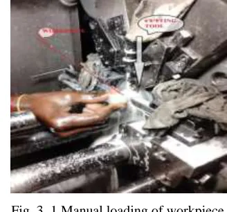
Fig. 3. 1 Manual loading of workpiece
Initially there were 24 machines, which were operated by 24 skilled operators along with 4 unskilled operators or helpers.
Problem in present are,
IJEDR1703129
International Journal of Engineering Development and Research (
www.ijedr.org
)
904
Skilled worker required.
Production time depends upon operator skill.
Tool break down problem due to misalignment of part.
Machining safety
Line balancing of the shop-floor. 5. OBJECTIVES
After evaluating the machining process at Tuljai Engineering works and literature, following are the objectives decided-
To make loading and unloading of the workpiece automatically i.e., process automation.
To enhance quality product.
To reduce labor cost.
To minimize worker interference from safety point of view.
Utilization of appropriate shop-floor by using line balancing techniques.
To increase productivity by reducing idle time of the machine by cellular manufacturing approach.
6. METHODOLOGY
The progress of the developing the project will be smooth and easier with well defined and proper planning and management. When the proposal submitted, the planning of the project is started in progress. Basically, crucial consideration of time management, resources and fact-finding procedures is carried out and considered at the initial stage, when the project has been approved. Planning is important as only sufficient time and resources are provided.
6.1
Existing method of manufacturing:Manufacturing is an important commercial activity carried out by companies that sell products to customers. In the modern sense, manufacturing involves interrelated activities that include product design and documentation, material selection, process planning, production, quality assurance, management, and marketing of products. These activities should be integrated to yield viable and competitive products.
In conventional way of manufacturing feeding of the work piece is done manually on turning machine. The operator holds the workpiece in his hand to load it on machine collet. As the workpiece is loaded on machine and held by collet for grooving and chamfering operation which is done simultaneously it leads to hazards from safety point of view. While the turning operation is done, coolant circulates continuously to carry out machining work smoothly. After the turning operation on workpiece is completed the job is ejected or unloaded by the machine automatically, further workpiece is stored in a storage bin. Rewinding behind when the workpiece is unloaded operator feeds new workpiece for turning operation on machine collet which is a part of sequential process. The stored workpieces are soaked in LH3 grade oil for ten minutes, to clean up and remove burr. The workpieces are inspected randomly before shifting to packaging department.
Thus by traditional way of manufacturing the company is facing problems like injury to operators, low productivity, high labor cost, poor quality etc. To overcome with this situation the automation of the whole process is needed. Manufacturing technologies have continually gone through gradual but revolutionary changes. These advancements in manufacturing technologies have brought about a metamorphism in the world industrial scene.
In order to overcome these problems discussed earlier in introduction, I have gone through number of research papers for finding appropriate solution and came to the conclusion, automation by robotic arm & automation by vibrating bowl feeder.
6.2 Proposed method of automation by vibrating bowl feeder:
IJEDR1703129
International Journal of Engineering Development and Research (
www.ijedr.org
)
905
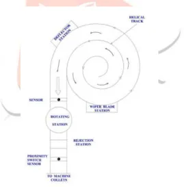
Fig. 6.1 Vibrating Bowl FeederWhen power is supplied to the feeder it starts vibrating with specific amplitude which cause to move work piece gradually in a defined helical path. As the job arrives at wiper blade station, jobs that are stacked on top of one another and also those jobs that are higher than the set height limit of the wiper blade get rejected or wiped off. The wiper blade station is a passive orienting device commonly used in the vibratory bowl feeder to reject or wipe off jobs. After fleeting wiper blade station work piece moves towards deflector station. Here the deflector station deflects the jobs by 90 degree and finally it travels through an inclined rail towards machine collet. Similarly, when number of jobs is in queue inside an inclined rail, at certain position Proximity Switch Sensor is positioned. The sensor provided on inclined rail will complete the close loop. When the jobs exceed its limit, sensor will cut off power supply of the vibrating hopper. In this way by cutting off power supply of vibrating hopper in idle time, we can reduce power consumption of the system. The schematic line diagram of feeding system is as shown in figure 5.3
Fig. 6.2 Schematic Diagram of Feeding System
IJEDR1703129
International Journal of Engineering Development and Research (
www.ijedr.org
)
906
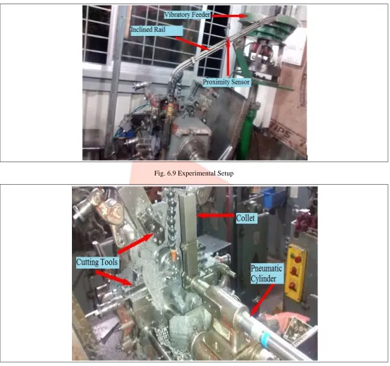
Fig. 6.3 ColletAfter loading the workpiece, machine performs chamfering and grooving operations simultaneously. Once the turning operation on work piece completes, it get ejected automatically and is stored in a storage bin. This process repeats itself until the work pieces retain in an inclined rail. From above report it can be concluded that process automation with cellular manufacturing, escorts the following advantages,
Space Reduction
Quality Improvement
Labor Cost Reduction
Improved Machine Utilization. 6.3 Comparison of proposed automation:
Manufacturing industries are compelled to move away from traditional setups to more responsive and dynamic ones. Many new concepts have emerged from these changes, sustained by strategies aimed at meeting the challenges arising from global markets. In order to overcome the traditional way of manufacturing we tried to implement process automation by robotic arm and vibratory bowl feeder. Comparing both methods, robotic arm leads to lots of limitations and involves many complexities. Robotic arm involves number of mechanisms, electronics components, sensors, microprocessor control units, hence bulky assembly. It require more work volume probably space utilization is more. In this industry as there are 24 machines, for process automation 24 robotic arms are needed to be installed and also it requires high precision, accurate programming along with a skilled programmer to develop an appropriate program. Thus in case of small scale industry automation by robotic arm is not affordable.
In manufacturing, part feeding for automatic assembly is a crucial issue, where parts are required to be reoriented for accurate feeding into an assembly line. In this industry, parts are fed and reoriented into a particular arrangement using vibratory bowl feeder. Implementing of vibratory bowl feeder has many advantages and it is energy efficient, comparative low cost, robust construction, portable, etc.Vibratory feeders offer a cost-effective alternative to manual labor, saving manufacturer time and labor cost. It also trims down power consumption, when certain number workpieces in inclined rail are in queue. Evaluating automation by robotic arm and automation by vibratory bowl feeder we can conclude that vibratory bowl feeder is greater feasible and affordable, this report preferred automation by vibratory bowl feeder.
6.4 Specification of cam & follower:
Cam and Follower is also called as track follower, which converts one form of motion into another form. It consists of different constraint motions that are rotary, oscillatory and reciprocatory. The follower during its stroke that is reciprocating may constitute simple harmonic motion, uniform motion or cycloidal motion as per application.
The cam and follower used in present application have following specifications, 1) FCJS-40 ( Sealed, with cage and thrust washer)
IJEDR1703129
International Journal of Engineering Development and Research (
www.ijedr.org
)
907
6.5 Specification of pneumatic cylinder:Pneumatic Cylinders also known as air cylinders are mechanical devices use the power of compressed gas to produce a force in a reciprocating linear motion. Pneumatic Cylinders forces a piston to move in the desired direction. The piston is a disc or cylinder, and the piston rod transfers the force it develops to the object to be moved. Engineers prefer to use pneumatics sometime because they are quieter, cleaner, and do not require large amounts of space for fluid storage.
Because the operating fluid is a gas, leakage from a pneumatic cylinder will not drip out and contaminate the surroundings, making pneumatics more desirable where cleanliness is a requirement.
1. Media: Air, Oil and inert-gases. 2. Temp. Range: 0° C to +65° C.
3. Pressure Range: Minimum 4bar to Maximum 10bar.
4. Cushions: For 19 and 25 mm bore rubber shock absorbers as optional. Above 25 mm bore adjustable cushions as standard. 5. Consumption: Liters of free air per 100 mm single stroke at 5 Kgf/cm2.
6. Bore to Stroke: Ø32 - 125 mm. 6.6 Traditional shop floor layout:
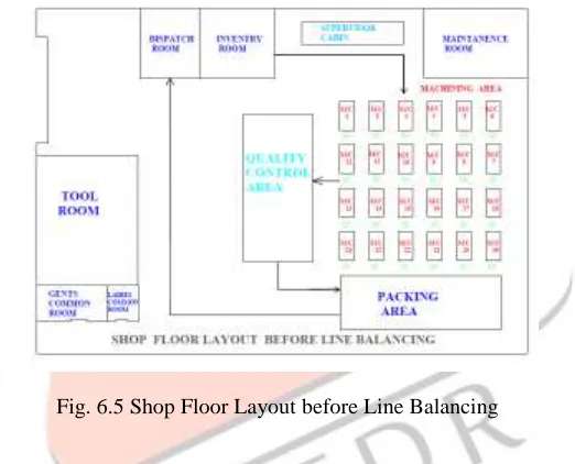
In conventional shop floor layout (figure 6.5) 24 machines were controlled by 24 operators which leads too many disadvantages discussed above. Also product cycle time required in present condition was high resulting in low productivity and poor machine utilization. To overcome, by implementing line balancing technique we have designed new or modified shop floor layout.
Fig. 6.5 Shop Floor Layout before Line Balancing 6.7 Proposed shop floor layout:
As stated earlier in problem definition, this industry is facing a problem regarding space utilization and line balancing of shop floor. With the help of modified shop floor layout (as shown in figure 6.6.) we have achieved line balancing technique. In this customized layout and automation of vibrating bowl feeder, four machines can be handled by single worker, thus decrease in labor cost. By implementing modified shop floor layout product cycle time has reduced resulting in high productivity, space reduction and better machine utilization.
IJEDR1703129
International Journal of Engineering Development and Research (
www.ijedr.org
)
908
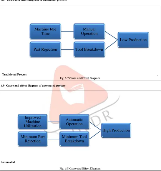
From above modified layout it is cleared that 6 workers can handle 24 machines, instead of 24 labors on 24 machines in traditional layout. Hence the cost of 18 labors can be saved.6.8 Cause and effect diagram of traditional process:
Traditional Process .
Fig. 6.7 Cause and Effect Diagram
6.9 Cause and effect diagram of automated process:
Automated
Fig. 6.8 Cause and Effect Diagram
6.10 Working setup of automated mechanism:
To overcome the existing problem automation of machining process was obligatory. Here we have installed vibrating bowl feeder to handle workpiece. An inclined rail is attached to the feeder to carry workpiece towards collet. The flow of workpiece is controlled to
Low Production
Manual
Operation
Machine Idle
Time
Tool Breakdown
Part Rejection
High Production
Automatic
Operation
Improved
Machine
Utilization
Minimum Tool
Breakdown
Minimum Part
IJEDR1703129
International Journal of Engineering Development and Research (
www.ijedr.org
)
909
the collet by proximity switch sensor, were energy efficiency can be achieved. Pneumatic cylinder which is actuated by cam & follower mechanism feeds the workpiece to machine collet by certain interval of time. The turning operation is carried out on workpiece, after machining job is automatically ejected and get store in storage bin. Then machined workpieces are soaked in LH3 grade oil for ten minutes to clean and remove burr. Further the workpieces are inspected randomly before shifting to packaging department.Fig. 6.9 Experimental Setup
IJEDR1703129
International Journal of Engineering Development and Research (
www.ijedr.org
)
910
7 RESULTS AND DISCUSSION:After implementation of new process it is required to evaluate total production and its cost. Available data for machining is taken for comparison with automated process. Below sheet shows daily production data for 24 machines in three shifts. These sheet also have part rejection, tool breakdown and operator injury records.
Total production cost before automation and after automation is calculated which is used for calculating total saving cost. Based on production expenditure different pie charts are plotted.
7.1 COST DISTRIBUTION OF OLD PROCESS:
Cost details of 24 machines for one month are shown in table 7.1. Here the most contributing parameter is labor costing which is 75% of total production expenditure. So, project mainly focus to optimize labor cost.
Sr. No. Parameter Unit Cost (Rs) Unit Total Cost (Rs)
1 Skilled Operator 12000 24 288000
2 Machine Maintenance 950 24 22800
3 Tool Break Down 840 36 30240
4 Electricity 8.25 2150 17740
5 Material Handling 6000 4 24000
Total
Expenditure 382780
Table7.1 Old Process Cost Distribution
Fig.7.1 Pie Chart - I 7.2 COST DISTRIBUTION OF REVISED PROCESS:
Cost details of 24 machines for one month after automation are shown in table 7.2. After implementing automation system labor cost is 18% of total production expenditure. So, project is able to achieve 56% reduction in labor cost.
Sr. No. Parameter Unit Cost (Rs) Unit Total Cost (Rs)
1 Skilled Operator 12000 06 72000
2 Machine Maintenance 950 24 22800
3 Tool Break Down 840 21 17640
4 Electricity 8.25 2830 23350
5 Material Handling 6000 4 24000
Total Expenditure 159790
6 Total Saving Amount - - 228600
IJEDR1703129
International Journal of Engineering Development and Research (
www.ijedr.org
)
911
Fig.7.2 Pie Chart – IIFig.7.3 Expenditure review
IJEDR1703129
International Journal of Engineering Development and Research (
www.ijedr.org
)
912
8 CONCLUSIONS AND FUTURE SCOPE
8.1 Conclusions:
1.
Manual feeding of workpiece was replaced by automatic system thus the idle time of machine is reduced which led to increase in productivity.2.
Automation system has better accuracy and precision over the traditional system which improved product quality.3.
Tool breakdown and part rejection which were at peak position in conventional system are minimized.4.
Currently Manufacturing industries are facing problem due to lack of skilled workers, by using automation we can cope up with this crisis.5.
Relation between technology and unemployment is very controversial, so there is need to utilize a technology that shares the gain in productivity so that unemployment is not a consequence of technological change.6.
With design of new shop floor layout production process flow is arranged in systematic way which had reduced cycle time.7.
Cellular manufacturing is key process to accomplish stated objectives of the project.8.2 Future scope:
As we know nothing is perfect in this world and technology needs continuous innovation. Also for this work there was some time constraint, so future development and possible changes are proposed.
When vibratory bowl feeder starts, workpieces fleet along the helical path. As the job arrives at wiper blade station, jobs that are stacked on top of one another and also those jobs that are higher than the set height limit of the wiper blade get rejected or wiped off. After fleeting wiper blade station work piece moves towards deflector station. Here the deflector station deflects the jobs by 90 degree. It is possible to arrange a sensor to detect the part orientation. If the workpiece is fleeting in a wrong orientation sensor will detect that part and send signal to rotating station for orientation the part. And if in rare case wrong oriented workpiece is not re-oriented by rotating station, further that part will be automatically discarded at rejection station. Thus we can achieve foolproofing of the system. Below figure 8.1 show schematic diagram of proposed feeding system.