Abstract—Mining readiness is continually emphasized. Training is conducted to ensure that selected aerial forces remain in a state of mine readiness. Naval air forces and mine assembly personnel are capable of rapid deployment to operate from overseas bases and carriers. Tactics for mine laying in a hostile environment are under constant development, and prepositioned mine stocks are held in a high state of readiness to support approved mining plans. Research and development continues for new mines and components, including such features as improved capabilities against submarine and surface targets, better resistance against minesweeping and hunting, more flexibility, easier and less expensive maintenance, simpler and faster preparation for laying, and improvement of mine detection and control systems with increased sophistication. A sophisticated technique for aerial mine presented in this paper including the technologies of the wireless communication to construct a mesh of aerial mine, and GPS technologies for the orientation positioning, also the ultrasonic techniques for target detection.
Index Terms—Air mine, GPS, ZigBee, ultrasonic.
I. INTRODUCTION
Naval and terrestrial mines are relatively low-cost and highly effective weapons. The threat of mines can deter an enemy from sending his surface ships, submarines, and troops into an area. Mines are difficult to locate and sweep. They can be set to activate when there are movement through the water, earth or generally any threats inside forbidden or prohibited zones be detected. [1]
Today's mines are designed for deployment against many different classes or types of troops to achieve a variety of results. However, to meet the challenges of the missions that they may be called upon to perform, mines are becoming increasingly complex. Moreover, the number of these missions is so large that no one mine can serve all purposes. What is the case if we have a forbidden or prohibited area my forces also the enemy obligatory should not pass over by the air planes due to International confederate treaties. At this case we should prevent any air planes or any aviation over these zones. The introduced suggestion is for an aerial mine design we can use it to present the coverage protection for these prohibited zones. [2]
The term mines also includes destructors which are general purpose bombs containing influence firing mechanisms. In general if we talk about the naval mines, some sea mine with small explosive charges are designed only for use against river boats and wooden vessels of small displacement. Other mines with large charges can destroy or damage most capital ships. Some mines are intended primarily for use against submarines. Although it has been said that mines are
Manuscript received November 11, 2011; revised December 8, 2011. Hussam Elbehiery is with Electrical Engineering Department, Benha University, Cairo, Egypt. (email: [email protected])
becoming increasingly complex, it is largely because of the intelligence that is built into their firing systems. Conversely, the same technology that made mines more complex in some ways has made them simpler in others. The newer mines, for example, have features which make assembly, testing, and stowing much easier and safer than was possible with older not-so-complex mines. [2]
Using the same concept in the naval or terrestrial mine, we are able to design the aerial mine to deal with various types of planes in the civilian or air forces of the enemy. When deployed, mines may be used as offensive or defensive weapons. As offensive weapons, they may be planted in the enemy prohibited zones. The actual threat of such mines is frequently of equal importance with the actual friendly plans, since the presence or threat of mines requires the necessary countermeasures to sweep or neutralize them. As defensive weapons, mines may be planted in perimeter defenses zones, or open waters to protect against enemy offensive air force attacks into these areas. [1]
II. DESCRIPTION
Use a `Predator` type air vehicle, loaded with high yield explosives, to orbit a forward edge of the battle area. The aerial mine (AM) might be triggered by noise, infra-red signatures, or an intruding trigger by ultrasonic sensor pre-loaded into a semi-artificially intelligent on-board processor. If a pre-programmed threat signature was detected, the predator would orient in a ready state against the threat and intercept. Ground control or mother ship control would allow for arming/disarming the AM.
If structural failure occurred in the ground control station, a self-disarm/self-destruct command could be built-in. This device could be used against incoming cruise missiles, aircraft, or observation platforms. If the AM becomes low on battery (it could be alternately solar powered for daylight operations), it could be safely landed and recharged and/or maintained. A similar use could be devised for a weather balloon-type AM for high altitude operations. Although the area location control and recovery are complicated the solution was the using a GPS modules in the AM sending its orientation by 5 Hz to the ground station [3]. Figure 1 shows the structural design for the Mine.
Fig. 1. Structural design for the Aerial Mine
Prohibited Zones Coverage Protection Using Aerial Mines
A. Method of Actuation
Mines can be activated by contact, target influence, or remote control. Contact mines are activated by physical touch and are the oldest and most common type. Target influence mines seek to detect air planes using a magnetometer, hydrophone, Infrared, ultrasonic or pressure device. Influence mines can be calibrated to detonate only near targets of a certain size. Controlled mines are remotely operated by a wireless connection to the ground station. [3]
A typical mine consists of an explosive case and a firing mechanism. More complicated mines may be outfitted with a variety of other features. A battery included in electronic mines; an arming device employed to make a mine active only after it has reached a certain range, a target counter that allows the mine to let a certain number of valid targets pass before detonating, and a clock delay that make the mine potent for a certain length of time, after which the mine will be in the standby mode. Air-delivered mines frequently fitted with a parachute or an engine to simulate the UAV (Unmanned Aerial Vehicle), or RPV (Remotely Piloted Vehicle). [1]
Acoustic mines employ a hydrophone to detect the sounds emanated by air planes including engine and propeller noises. Such sounds must meet certain criteria, including frequency band and must increase in volume at a prescribed rate or the mine will ignore them. Pressure mines use electro-hydraulic pressure sensors to detect ships or submarines. The pressure sensor waits for the pressure drop associated with the passing of a vessel and, if the target vessel is displacing enough air, the mine will actuate. [1]
III. AERIAL MINES SPECIFICATIONS AND APPLICATIONS
The suggested technique for the aerial mines is a low cost, unmanned perimeter defense, preprogrammed against specific enemy threats, human control ground/air fusing and disarming control, automatic fail safe control for in-flight failure – Recoverable.
Sophisticated air planes launched, also the weapons with extremely high velocities are immune. New weapons systems with new IR or noise signatures would not be recognized. Muffled or altered noise IR signatures might be exempt from detection. Also the new air forces supported by Airborne lasers could attack these AM.
Protect Civilian Airports from terrorist attacks - Protect Civilian populations or foreign located business from attack.
IV. AIR MINES TYPES
There are two main types of air mines up to the way of control; Parachute bombs (Aerial mines) and air mines. There is another classification of the air mine but up to the actuation method; Contact mines using IR, Ultrasonic or Acoustics sensors, and remotely controlled mines. [2]
A. Contact Mines
Which need to be touched by the target before they detonate, limiting the damage to the direct effects of the explosion and usually affecting only the single vessel that triggers them. The earliest mines were usually of this type.
They are still used today, as they are extremely low cost compared to any other anti-aircraft weapon and are effective, and Limpet mines: which are a special form of contact mine which are attached to the target by magnets and left, and are so named because of the superficial.
B. Remotely Controlled Mines
Frequently used in combination of aircrafts, controlled mines (or command detonation) mines can be in place in peacetime, which is a huge advantage in blocking important shipping routes. The mines can usually be turned into "normal" mines with a switch (which prevents the enemy from simply capturing the controlling station and deactivating the mines), detonated on a signal or be allowed to detonate on their own.
V. AERIAL MINE STRUCTURAL DESIGN
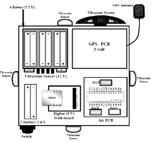
The structural design consists of two main parts. The first part called the ground station and the second part called the aerial unit as shown in figure 2.
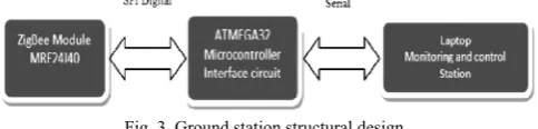
The ground station includes a PC or Laptop as a display unit including software to display the orientation of the aerial unit due to the information coming from GPS module settled in the aerial unit. It includes also an interface circuit to transmit and receive the commands from and to the aerial unit through the zigbee module.
The aerial unit includes rechargeable batteries and its indication circuit, GPS module and its interface circuit, zigbee module and its interface circuit, ultrasonic sensing system for ranging of the target detection.
Fig. 2. Structural design of Aerial Mine
VI. GROUND STATION DESIGN
The PC software in Microsoft Visual Basic 6 because of its really quick and easy to do also provided with MS Comm. control to talk to the serial port reliably. The result was a rather slick graphical program to capture data from the radio modem, display it graphically, and send commands remotely to the aerial unit. Figure 3 explains the ground station structural design.
Fig. 3. Ground station structural design
address to not making a conflict with the other aerial units. The zigbee module used in the ground station could connect up to 64 aerial modules at the same time without any conflict. Also all the data sent and received from and to the aerial unit have the ability to be encrypted by an AES cryptography module giving a protection against any intruding techniques.
All the firmware programs have been written in C++ and compiled it with WinAVR (avr-gcc for Windows). There was a lot of trial and error involved, and a lot of serial port probing, but eventually I had everything tweaked.
VII. AERIAL UNIT ELECTRONIC DESIGN
A. Aerial Unit Logic Board
The logic board is the "brains" of Air Mine. Employing an 8-bit microcontroller and a few ICs, Air Mine interfaces with a number of devices including Ultrasonic sensors, GPS Module, Wireless sensor, charging circuit for battery and serial EEPROM memory. The code has been written in C, compiled with AVR and downloaded to the microcontroller via In-Serial Programming (ISP) cable connected to the PC's. Figure 4 describe the flowchart of the logic board:
Fig. 4. Logic board flowchart for the Aerial unit
Fig. 5. Aerial unit structural design
The logic board contains an Atmel Atmega32 microcontroller and a number of local peripherals, including
two sockets for SPI EEPROM ICs, a MAX7456 on-screen display IC, two analog multiplexers, two MAX232 serial transceivers, and a 5V voltage regulator. The Atmega 32 can handle synchronous and Asynchronous data, from the serial port of a PC are asynchronous. I could have written some software to do this, but I really wanted it to be taken care of in hardware. The logic board's specifications are outlined in the figure 5.
B. Radio Modem board
IEEE 802.15.4™ 2.4 GHz RF Transceiver (ZigBee transceiver) is used for the wireless communication between the Aerial unit and the Ground station. The device type has been used is MRF24J40 is an IEEE 802.15.4™ Standard compliant 2.4 GHz RF transceiver. The MRF24J40 creates a low-cost, low-power, low data rate (250 or 625 kbps) Wireless Personal Area Network (WPAN) device. [4] and [5]
The MRF24J40 interfaces to many popular Microchip PIC® microcontrollers via a 4-wire serial SPI interface, interrupt, wake and Reset pins. The MRF24J40 provides hardware support for:
•Energy Detection. •Carrier Sense. •Three CCA Modes. •CSMA-CA Algorithm.
•Automatic Packet Retransmission. •Automatic Acknowledgment.
•Independent Transmit, Beacon and GTS FIFO Buffers. •Security Engine supports Encryption and Decryption
for MAC Sub-layer and Upper Layer.
These features reduce the processing load, allowing the use of low-cost 8-bit microcontrollers. The design needs two Zigbee modules in Air Mine. Zigbee module can be used without any extra hardware and can easily be synthesized in software with a microcontroller. A Zigbee module is fast, typically somewhere between 3200 bps to 38400 bps at least. [6] and [7]
C. GPS Module Interface
The aerial mine design considered with APRS (Automatic Position Reporting System). We decided early on pursue APRS as GPS module because it is commercially-available and not expensive and I figured it out the protocol in order to design my own hardware. [8]
A cost effective, high-performance u-blox 5 based LEA 5 series of GPS/GALILEO module has been used in the research. The LEA-5 module series by u-blox sets a new standard for GPS and GALILEO receiver modules. Featuring the high performance 50-channel u-blox 5 technology, these modules provide excellent performance and flexibility at an economical price. [9]
best-in-class acquisition and tracking sensitivity. This arrangement allows the GPS and GALILEO engine to simultaneously track up to 16 satellites while searching for new ones. U-blox 5’s advanced jamming suppression mechanism and innovative RF architecture provides a high level of immunity to jamming, ensuring maximum GPS and GALILEO performance [10]. Figure 6 describes in details the GPS module circuit diagram.
Fig. 6. GPS Module circuit diagram
U-blox 5 has a 4 Hz position update rate, and -160dBm Super-Sense sensitivity. LEA-5 modules support a number of peripheral interfaces for serial communication. The embedded firmware uses these interfaces according to their respective protocol specifications. For specific applications, the firmware also supports the connection of peripheral devices, such as external memories or sensors, to some of the interfaces. [11]
U-blox 5 uses two types of protocols; NMEA and UBX. Both protocols are available on UART, USB, DDC (Display Data Channel) and SPI. [12]
D. Ultrasonic Sensing
Ultrasonic sensors (also known as transceivers when they both send and receive) work on a principle similar to radar or sonar which evaluate attributes of a target by interpreting the echoes from radio or sound waves respectively. Ultrasonic sensors generate high frequency sound waves and evaluate the echo which is received back by the sensor. Sensors calculate the time interval between sending the signal and receiving the echo to determine the distance to an object. Lower costs and ease of use have led machine designers to incorporate ultrasonic sensors into applications that were once considered too difficult or too costly [13]. Figure 7 explain the ultrasonic system structural diagram.
1) Characteristics of Ultrasound
The sound wave propagation speed (v) with temperature compensation can be calculated by the following formula V= 331.5 + 0.6*T [m/sec] (1) where T is the air temperature (Co).
Fig. 7. Ultrasonic system structural diagram
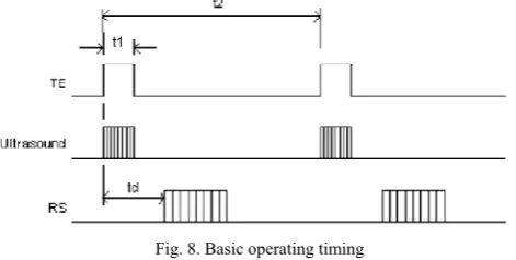
Range measurement starts from the rising edge of TE. Then the controller set TE to low (logic 0) after t1 (250 µsec).
The controller should measure the time interval td from the rising edge of TE to the first rising edge of RS, which is the returned sound wave. td is equal to two times of the travelling
time between the sensor to the object (transmitting and echoing). The time period between two measurements should be no less than 20 msec. If the minimum distance that the sensor can measure is 100 m, that means that if the range is less than 100 m, it will be reported as a 100 m. That is shown in figure 8.
Fig. 8. Basic operating timing
The distance to object (in meter) can be obtained as follows:
Distance to object (meter) = td (second) * V (meter/second)/2 Ultrasound is an acoustic wave with a very high frequency, beyond human hearing. Since the audible frequency range is said to be between 20Hz and 20 kHz, ultrasound generally means acoustic waves above 20 kHz. Ultrasound has several characteristics which make it so useful and that have led to its use in many electronics applications. Firstly, it is inaudible to humans and therefore undetectable by the user. Secondly, ultrasound waves can be produced with high directivity. Thirdly, they are a compressional vibration of matter (usually air). Finally, they have a lower propagation speed than light or radio waves. The fact that ultrasound is inaudible to human ears is an important factor in ultrasound applications. [14]
(that is emitting the ultrasound) and the frequency at which it vibrates. [15]
2) Directivity of ultrasonic sensors
By using higher frequency and selecting an appropriate amplifier (gain), we can increase the influence of objects. While narrower vertical directivity improves sensor usability, wider horizontal directivity can provide wider coverage with fewer sensors. "Asymmetric" ultrasonic sensors (see figure 9) are used in such situations. [13]
Fig. 9. Directivity types for ultrasonic sensors
3) Detection types of ultrasonic sensors
•Proximity Detection
Proximity detection is the detection of an object at a given range. The detection range of the RPS-400-30 can be controlled by a resistor or potentiometer wired to the green and black leads of the unit, and is adjustable to the desired detect distance. Any object within the desired range is detected, while objects outside the desired range are ignored. The detect point is independent of size, material, or reflectivity [15]. (See figure 10).
•Hysteresis Detection
The RPS-400-30 can be furnished with Hysteresis Control capability. The Hysteresis sensor has a fixed detect point equal to the sensors minimum range and an adjustable turnoff point up to the sensors maximum range. Simply stated, an object will be detected at the minimum range, and will remain detected until the object is no longer within the adjustable turnoff point [16]. (See figure 10).
Fig. 10. Detection types for ultrasonic sensors
4) Power Supply Board
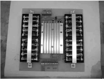
The power supply board is a simple design that employs lithium battery and two LM2941 low-dropout linear regulators to provide multiple regulated DC outputs. The 20 AA lithium are split into two banks of 10 in parallel giving a nominal 15V. Since each cell is rated at 2900 mAh, the total battery capacity is 5800 mAh giving about 3 1/2 hours of
runtime with all systems running. [17], [18], and [19] There is an unregulated 15V output, as well as two regulated 11.5V and 6.2V outputs supplied by separate LM2941 ICs. The LM2941's are described very ambiguously in the datasheet as capable of supplying "over 1 A." They datasheet seems to imply that they are rated at 1A, but can deliver larger currents when properly heat-sinked. With the aid of the large aluminum heat-sink I used, I found that I could indeed pull well over 1 A on both regulated outputs with no issues. [20] A photo of the board and some info on the power distribution is shown in figure 11.
Fig. 11. Power supply distribution unit layout
The overall design need a monitoring circuit for the power supply unit until the charging become low, we should exchange the power supply unit with other full charge to maintain the charge is high giving the highest time stay the aerial unit without any change. [21] and [22]
The analogue to digital converter port in the microcontroller in the logic board of the aerial unit has been used as a monitoring circuit. We use the output voltage of the battery as the input to the A/D port in the ATMEGA 8 then after converting to a digital code will be sent to the ground station. The digital code sent to the ground station as a monitoring data for the charging level of the aerial unit batteries.
VIII. BALLOON
We use inflatable balloon filled with helium with a pay load of almost 3Kg which ids the approximate weight of the aerial unit, tied with a nylon string to the orientation of the ground station or position predetermined for the mesh of aerial mines purposes.
IX. CONCLUSION
Finally, the design makes it incredibly easy to remove all the parts at once from the payload to make changes. The suggested design achieved and tested in two places; one in a flat area in a desert, and the second in urban area. Some problems affect on the communication link in the experiments in urban area.
ACKNOWLEDGEMENT
This work was supported by faculty of engineering - Benha University - Cairo/Egypt. I would thank kindly Assoc. Prof. M. Tarek Elewa for supporting this researching part of this work.
REFERENCES
[1] NAVSEA Mine Familiarizer, “Naval Mine Warfare Engineering
Activity,” USA, April 1985.
[2] Frederik M. Sallagar, “Lessons from an Aerial Mining campaign
(Operation ‘Starvation’),” United States Air Force Project RAND, R1322-PR, Santa Monica, CA, USA, April 1974.
[3] U.S. Navy Mine Countermeasures Familiarizer, “Naval Mine Warfare
Engineering Activity,” October 1991.
[4] Raul Morais, Miguel A. Fernandes, Samuel G. Matos, Carlos Serôdio,
P. J. S. G. Ferreira, and M. J. C. S. Reis, “A ZigBee multi-powered wireless acquisition device for remote sensing applications in precision viticulture,” Journal of Computers and Electronics in Agriculture, Volume 62 Issue 2, Elsevier Science Publishers B. V. Amsterdam, Netherlands, July, 2008.
[5] Khusvinder Gill, Shuang-Hua Yang, Fang Yao, and Xin Lu, “A
ZigBee-Based Home Automation System,” IEEE Transactions on Consumer Electronics, Vol. 55, No. 2, May 2009.
[6] Jingcheng Zhang, Allan Huynh, Qinzhong Ye, and Shaofang Gong,
“Reliability and Latency Enhancements in a ZigBee Remote Sensing System,” Proceeding of SENSORCOMM '10, Proceedings of the 2010 Fourth International Conference on Sensor Technologies and Applications, IEEE Computer Society Washington, DC, USA, 2010.
[7] Microchip Technology Inc., “MRF24J40, IEEE 802.15.4™ 2.4 GHz
RF Transceiver,” Data Sheet.
[8] Alison Brown and Ben Mathews, “Remote Sensing using Bistatic GPS
and a Digital Beam Steering Receiver,” Proceedings of ION GNSS 2005, Long Beach, California, September 2005.
[9] I. Colomina, F. Creixell, M. Wis, “A General INS/GPS system for
Remote Sensing and Geodesy,” Institute of Geomatics, Generalitat de Catalunya & Universitat Politecnica de Catalunya, Castelldefels, SPAIN, 2003.
[10] R. N. Çelik, T. Ayan, R. Deniz, and M. T. Özlüdemir, “Geodetic
infrastructure of TURKEY for GIS, GPS and Remote Sensing applications,” ITU, Civil Engineering Faculty, Maslak, Stanbul, Turkey 2004.
[11] Khali Aziz Hamzah, “Remote Sensing, GIS and GPS as a tool to
support precision forestry practices in Malaysia,” The 22nd Asian Conference on Remote Sensing, Singapore, 5 – 9 November 2001.
[12] Jay Gaoa, and Yansui Liu, “Applications of remote sensing, GIS and
GPS in glaciology,” SAGE Journals, Progress in Physical Geography Journal 25 (4), pp. 520–540, 2001.
[13] Dipl. Ing, and Dirk Bank, “A High performance Ultrasonic Sensing
System for Mobile Robots, MORPHA project, Science Research and Technology (BMB +F), German Ministry of Education, ULM, 2002.
[14] Kaniak, G., and Schweinzer, H., “Advanced ultrasound object
detection in air by intensive use of side lobes of transducer radiation pattern,” International Conference on Science Education for the Next Society (ICSENS), Seoul National University, Korea, October 30 to November 1, 2008.
[15] Dobie G., Spencer A., Pierce S. G., Galbraith W., Worden K., and
Hayward G., “Simulation and Implementation of Ultrasonic Remote Sensing Agents for Reconfigurable NDE Scanning,” Proceedings of the 35th Annual Review of Progress in Quantitative Nondestructive Evaluation, AIPC Conference Proceedings, Volume 1096, pp. 990-997, Coruña, Span, 4-8 July 2009.
[16] Pentti Mattila, Jouni Siirtola and Risto Suoranta, “Two-dimensional
object detection in air using ultrasonic transducer array and non-linear digital L-filter,” Elsevier Science Publishers B.V., Amsterdam, Netherlands, Sensors and Actuators A: Physical, Volume 55, Issues 2-3, Pages 107-113, 31 July 1996.
[17] Yao-Ching Hs ieh, Chi-Kang Wu, and Chin-Sien Moo, “A Multi-Mode
Charging Circuit for Rechargeable Batteries,” The 2005 International Power Electronics Conference (IPEC’05), pp. 1569- 1574, Niigata, Japan, April 4-8, 2005.
[18] F. B. Diniz, L. E. P. Borges, B. de B. Neto, “A Comparative Study of
Pulsed Current Formation for positive plates of Automotive Lead Acid Batteries,” Journal of Power Sources, Vol.109, No.1, pp. 184-188, June 2002.
[19] Swagatam-Majumdar's Hubfolio, “Build a Universal Constant Current
Charger for Lead Acid Battery, Portfolio of professional writers, Article by Swagatam , 3rd December 2010.
[20] Michael Kovalcik, “Constructing a Lithium-Ion/Polymer Battery with
an Imbedded Protection Circuit Module (PCM),” Michigan State University, ECE 480-FS08, USA.
[21] Sabin Lupan, “UPS Battery Charger Options,” The Web’s Leading
Power Electronics Publication – Darnell Group, Power Integrations Inc., San Jose, California, USA.
[22] John A. O’Connor, “Simple Switch mode Lead-Acid Battery Charger,”
UNITRODE Corporation, Texas Instruments Incorporated, USA, 1999.