REVERSE OSMOSIS PLANT DESIGN AND EVALUATION - A
CASE STUDY
Y. Kamala Raju1, RathodRavinder2
1.INTRODUCTION
1.1 Need For Reverse Osmosis Plants
A recently released UN world water development report 2006, determining standards of water quality ranks India as low as 120 among 122 member countries. The report brings out fact that 70-80% of all illnesses are reported due to water contamination. According to Central Ground Water Board (CGWB) the annual withdrawal in south Delhi has touched 234%. Thus voicing the alarming dip of Ground Water table to 65m below Ground level. Much of West Bengal‟s urban water supply depends on its falling levels of Ground Water and there is problem of Arsenic contamination both in urban and rural areas. The Energy Research Institute (TERI) recently announced a shocking fact about the 30 lakh liters of water being wasted every day at new Delhi railway station. The water is being used for washing of coaches, cleaning of platforms, and running taps. The TERI study proposes to construct a water recycling plant as a pilot project, which can become a model for other railway stations and help in prevention of water loss of around 85-95% being used for washing drains. Tap water in Patna is highly contaminated and 30-35% of it is not fit for drinking purpose.
Mr. Gerard Payen, Environment Advisor to former Secretary General of U.N. Mr.Kofi Annan said that Reverse Osmosis had took the place of instantaneous distillation Technology, thus reducing the cost and making the lives of the residents in coastal areas of world much easier. Desalination of sea water gets cheaper to as much as 10 times than it was in 1990‟s because of Reverse Osmosis process.
The new Thirty six million Gallon per day (136380 m3/day) Sea Water Reverse Osmosis (SWRO) plant in Singapore is the largest of its kind in Asia and one of the largest in the world is constructed by Black and Veatch, a leading Global engineering and construction company. The Reverse Osmosis systems for both residential and Industrial needs are now being supplied by different companies. The list of companies is given in annual buyer‟s guide of “Everything About water”. Approximately there are 774 no.s of companies in Industrial sector and 941 no.s of companies in Residential sector, dealing with Reverse Osmosis. (EA water Pvt. Ltd., 2006)
The Saudi Arabian Saline Water Conversion Corporation (SWCC) is planning to upgrade a de-salination plant and build a new one with larger capacity. Desalination forms a significant part in solution to Algeria‟s water demand. The Chennai water desalination limited, a special purpose vehicle (SPV) floated for executing a 100 Million litre a day (MLD), desalination project at Kattupalli village in Tamil Nadu, is undertaking the significant desalination project in India. (Water today, 2006) The hindon river in western utter pradesh has become one of india‟s most polluted rivers due to callous industries and indifferent authorities, according to a new study released by Janhit foundation. A 200 crore rupee project for recycling waste water for Industrial use in Gujarat will begin from April 2007 and is expected to be commissioned in December 2008. The project will be the first of its kind to the state entering into joint venture to foreigncompany. (EA Water Pvt. Ltd. 2007). The Reverse Osmosis Technology is needed in common Effluent treatment plants, where re-use of waste water is contemplated. Nearly Hundred common effluent treatment plants (CETPs) are operating in India today, serving clusters of small and medium scale Industries (Jeedimetla Effluent Treatment Limited, 2005).
1 Assistant Professor, Dept. of Civil Engineering, GRIET, TS, India. 2 Assistant Professor, Dept. of Civil Engineering, GRIET, TS, India.
DOI: http://dx.doi.org/10.21172/1.103.01
e-ISSN:2278-621X
Abstract- The practices of safe water with Nano filtration by Reverse Osmosis plants (both residential and industrial) to meet the UN Millennium development goal of combating Clean Water and Sanitation. It describes the Observations made at the Residential Reverse Osmosis plant at Hyderabad. The goal of combating Clean Water and Sanitation can be met by providing safe drinking water by Reverse Osmosis Plants. The present study on “Practices in Civil Engineering for sustainable community Development to meet one out of total seventeen Millennium Development Goals of United Nations by the year 2030” has been taken up to improve the quality of life of Global Community by creating awareness in all concerned. The present study is also relevant during the United Nations of sustainable development by 2030. A Reverse Osmosis Plant in a fourteen Stored building is evaluated for its performance. The design steps and the Popular and free software for the design of membranes of US company Hydronautics is explained.
1.2 Principles Of Reverse Osmosis And Nanofiltration
The phenomenon of osmosis occurs when pure water flows from a dilute saline solution through a membrane into a higher concentrated saline solution. The phenomenon of osmosis is illustrated. A semi-permeable membrane is placed between two compartments. “Semi-permeable” means that the membrane is permeable to some species, and not permeable to others. Assume that this membrane is permeable to water, but not to salt. Then, place a salt solution in one compartment and pure water in the other compartment. The membrane will allow water to permeate through it to either side. But salt cannot pass through the membrane.
1.3 Osmosis
Water diffuses through a semi-permeable membrane toward region of higher concentration to equalize solution strength. Ultimate height difference between columns is “osmotic” pressure.
1.4 Reverse Osmosis
Applied pressure in excess of osmotic pressure reverses water flow direction. Hence the term “Reverse Osmosis”. As a fundamental rule of nature, this system will try to reach equilibrium. That is, it will try to reach the same concentration on both sides of the membrane. The only possible way to reach equilibrium is for water to pass from the pure water compartment to the salt-containing compartment, to dilute the salt solution. The osmosis can cause a rise in the height of the salt solution. This height will increase until the pressure of the column of water (salt solution) is so high that the force of this water column stops the water flow. The equilibrium point of this water column height in terms of water pressure against the membrane is called osmotic pressure.
Figure 1 Overview of OsmosisFigure 2 Reverse Osmosis Process
If a force is applied to this column of water, the direction of water flow through the membrane can be reversed. This is the basis of the term reverse osmosis. Note that this reversed flow produces a pure water from the salt solution, since the membrane is not permeable to salt.
1.5 How Nanofiltration Works
The Nanofiltration membrane is not a complete barrier to dissolved salts. Depending on the type of salt and the type of membrane, the salt permeability may be low or high. If the salt permeability is low, the osmotic pressure difference between the two compartments may become almost as high as in reverse osmosis. On the otherhand, a high salt permeability of the membrane would not allow the salt concentrations in the two compartments to remain very different. Therefore the osmotic pressure plays a minor role if the salt permeability is high.
1.6 How to Use Reverse Osmosis and Nanofiltration in Practice
In practice, Reverse Osmosis and Nanofiltration are applied as a crossflow filtration process. Recovery is the percentage of membrane system feedwater that emerges from the system as product water or “permeate”. Membrane system design is based on expected feedwater quality and recovery is defined through initial adjustment of valves on the concentrate stream. Recovery is often fixed at the highest level that maximizes permeate flow while preventing precipitation of super-saturated salts within the membrane system. Rejection is the percentage of solute concentration removed from system feedwater by the membrane. In reverse osmosis, a high rejection of total dissolved solids (TDS) is important, while in nanofiltration the solutes of interest are specific, e.g. low rejection for hardness and high rejection for organic matter. Passage is the opposite of “rejection”, passage is the percentage of dissolved constituents (contaminants) in the feedwater allowed to pass through the membrane. Permeate is the purified product water produced by a membrane system.
1.7 Factors Affecting Reverse Osmosis AndNanofiltration Performance
Permeate flux and salt rejection are the key performance parameters of a reverse osmosis or a nanofiltration process. Under specific reference conditions, flux and rejection are intrinsic properties of membrane performance. The flux and rejection of a membrane system are mainly influenced by variable parameters including:
1) Pressure 2) Temperature 3) Recovery
4) Feed water salt concentration
The following graphs show the impact of each of those parameters when the other three parameters are kept constant. In practice, there is normally an overlap of two or more effects. Figures are qualitative examples
of reverse osmosis performance. In nanofiltration, the salt rejection is less depending on the operating conditions.
Not to be neglected are several main factors which cannot be seen directly in membrane performance. These are maintenance and operation of the plant as well as proper pretreatment design. Consideration of these three „parameters‟, which have very strong impact on the performance of a reverse osmosis system, is a must for each OEM (original equipment manufacturer) and end user of such a system.
Pressure: With increasing effective feed pressure, the permeate Total Dissolved Solids (TDS) will decrease while the permeate flux will increase as shown. Temperature: If the temperature increases and all other parameters are kept constant, the permeate flux and the salt passage will increase as shown.
Recovery: Recovery is the ratio of permeate flow to feed flow. In the case of increasing recovery, the permeate flux will decrease and stop if the salt concentration reaches a value where the osmotic pressure of the concentrate is as high as the applied feed
Pressure :The salt rejection will drop with increasing recovery as shown in Figure. Feedwater Salt Concentration: Figure shows the impact of the feedwater salt concentration on the permeate flux and the salt rejection.
1.8 Membrane Processes
For removal of dissolved and suspended impurities various membrane processes were developed. (Apex Consultants, Mumbai, 2006)
1. Particle filtration : 10 microns onwards 2. Micro-filtration : 0.1 to 10 microns 3. Ultra-filtration : 0.002 to 0.2 microns 4. Nano-filtration : 0.0008 to 0.003 micron 5. Reverse Osmosis : 0.0001 to 0.002 micron
1.9 Pretreatment Systems
A well designed and operated pretreatment system causes a steady and long membrane life. Pretreatment system should remove impurities which can cause scaling and fouling of the membranes. Major membrane failures can generally be traced to inadequacies in pretreatment systems. Colloidal matter must be removed by proper coagulation and media filtration. Problem more prevalent in surface water and in water recycle applications. Use of Ultrafiltration membranes upstream of reverse osmosis membrane is also effective. Silt density index must be regularly monitored to rule out excessive presence of colloidal matter. Iron and manganese cause fouling of membranes requiring cleaning. Iron and manganese can be removed by micro-filtration. Iron can be removed by the resin used in base exchange softener.
Organic matter can be dissolved or colloidal. Organic matter can be removed by Biological oxidation, chemical oxidation using chlorine, ozone sometimes in combination with Ultra Voilet (UV), Flocculation and settling, Activated carbon, Ultrafiltration membrane.
Microbiological impurities can be removed by disinfection techniques such as Chlorination, Ultra violet units, Ozonation. To increase the efficiency and life of Reverse Osmosis and Nanofiltraition (RO/NF)
system, effective pretreatment of the feed water is required. Selection of the proper pretreatment will maximize efficienc y and membrane life by minimizing.
Fouling
Scaling
Membrane Degradation
System Design for Reverse Osmosis Reverse Osmosis system Design comprises of 1) Determining pretreatment requirement
2) Selection of membrane 3) Defining system configuration 4) Designing for operating condition
Reverse Osmosis Design software given by Membrane manufacturers are useful to plant designer to decide a membrane system configuration which is technically optimized and accurate. It allows a designer to try out different combinations quickly and also get details of accessories such as pump flow and pressure. Some of the popular Reverse Osmosis.(R.O.) Membranes are as follows :
• Hydronautics, USA • Dow, USA
• Osmonics, USA • Toray, Japan
A five software to design membranes of Reverse Osmosis can be developed from www.hydronautics.com Input required for the software:
1. Project details 2. Water source/analysis 3. Temperature/pH
4. Product water quantity requirement
Based on the above inputs, software calculates the Feed TDS as well as scaling tendency of water.
1.10 User interface of the software:
Based on the above results, user has to decide on use of acid/anti-scalant dosing, if any. Next step is to choose type and size of membrane. The user then calculates the approximate number of membrane elements and the initial membrane configuration. Generally for 5 m3/h and above, 8 inch membranes are preferred. Once this data is input into the program, it generates output related to following parameters:
1. Detailed permeate and reject water analysis 2. Scaling tendency of water.
3. Net driving pressure requirement 4. Concentration polarization (Beta factor)
1.11 Output of the software:
Error messages, if any, related to minimum flow per vessel, higher beta factors are also displayed. Based on review of this output, user can now change % recovery, element type/pressure vessel configuration and recalculate the results. All these results can be saved for comparison.
2. DESIGN FOR REVERSE OSMOSIS
Pressure vessels: Elements are housed in pressure vessels. Length of pressure vessels can be one element long to seven element long considering process advantages, cost economics as well as ease of transportation. Higher number of the membranes housed in one pressure vessel is better arrangement.
Side Ported Design :This provides advantage of elimination of feed header and reject headers. This results in compact RO unit pipe work.
High Pressure Pumps:
Types of High pressure pumps are - Reciprocating
- Multistage Centrifugal
Permeate Dump Valve :This valve opens and allows permeate to drain automatically when quality of permeate with respect to conductivity is not satisfactory, to prevent bad quality water from entering permeate storage tank.
Anti-scalant Dosing: These are the chemicals when added to water containing higher amount of scaling salts, it prevents scaling even at higher concentration of salts.
Acid Dosing: Acids when added to water containing higher amount of bicarbonates, reduces the scaling tendency of water. Lower pH also helps reduce rate of hydrolysis of membranes.
Reject Recycle :When feed water contains lower amount of salts and permeate water quality requirement is not stringent, part of the reject is recycled to the suction of high pressure pump. This helps in achieving higher overall recovery.
Multiple RO units: At higher flow requirements, it become economical to use multiple number of units operating at lower flow rates to produce desired quantity of treated water. This arrangement helps in providing standby arrangement. It also helps continuity of operation.
3. OBSERVATIONS AT RESIDENTIAL REVERSE OSMOSIS PLANT – A CASE STUDY
Primary settling filter inlet pressure : 2.4kg/m2 Activated carbon filter inlet pressure : 2.2 kg/m2 Softening plant pressure : 2.1 kg/m2
pH : 6.6
High pressure pump suction pressure : 0
Discharge pressure 100 Psi
Reject pressure : 80 Psi
Rotameter Readings
permeate : 1.2m3 /hr
Reject : 2m3 /hr
From Rotameter the water is mixed with Sodium Hypochloride dosing to avoid algae smell. The R.O plant is operated for 8 hours a day. Pneumatic pump is used to pump water to the 8th floor.
4. RESULTS AND DISCUSSION
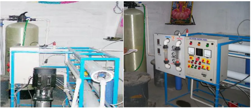
The Reverse Osmosis process removes dissolved and suspended impurities of sizes ranging from 0.0001 to 0.002 microns. The Residential Reverse Osmosis plant at Fourteenstorey building in Hyderabad is visited by the project team and the photographs taken are shown in photos. As it is evident from the photos that the borewell water is first fed in two large settling tanks for pre-treatment and then passed into primary settling filter, Activated carbon filter and softening plant then the water is led into the nanomembranes (which are important and costly), under high pressure pump.
The control panel of the Reverse Osmosis plant is as shown in Photo. The control panel contains Rotameter which measures the discharge of permeate and reject water. The permeate discharge is found to bhe 1.2 m3/hr. From Rotameter, the water is mixed with Sodium hypochloride dosing to avoid algae smell. The R.O plant is operated8 hours per day. Pneumatic pump is used to pump water to higher floors of the building. The primary settling filter inlet pressure, activated carbon filter inlet pressure and softening plant pressure are observed to be 2.4 kg/m2, 2.2 kg/m2 and 2.1 kg/m2respectively. The pH of the water is observed to be 6.6 which indicate that the water isacidic. The electrical conductivity of the water is found to be 50 micro siemens which is les than 250 micosiemens. This indicates the borewater is low salinity water, it can be used for irrigation along soils and on most crops. The discharge pressure and reject pressure are obsorbed for the 100 psi and 80 psi respectively.
The photos show the observations made in the “Reverse Osmosis Plant”.
Figure 3 Reverse Osmosis System Control Panel
5. CONCLUSION
A Reverse Osmosis Plant of INDWA Technologies Pvt. Ltd. Hyderabad in a fourteen Stored building in Hyderabad is evaluated for its performance. The design steps and the Popular and free software for the design of membranes of US company Hydronautics is explained. Reverse Osmosis Plants are recommended both at residential and industrial establishments to have safe drinking water as nearly eighty percent of all diseases are water borne. Scaling and Total Dissolved Solids (TDS) can also be reduced by Reverse Osmosis Process
.The Reverse Osmosis process removes dissolved and suspended impurities of sizes ranging from 0.0001 to 0.002 microns. 1. The permeate discharge is found to be 1.2 m3/hr.
2. The primary settling filter inlet pressure, activated carbon filter inlet pressure and softening plant pressure are observed to be 2.4 kg/m2, 2.2 kg/m2 and 2.1 kg/m2respectively.
3. The pH of the water is observed to be 6.6 which indicate that the water isacidic.
4. The electrical conductivity of the water is found to be 50 micro siemens which is less than 250 micosiemens. This indicates the bore water is low salinity water, it can be used for irrigation along soils and on most crops. The discharge pressure and reject pressure are observed for the 100 psi and 80 psi respectively.
Hence the Reverse Osmosis Technology is to be recommended widely both at residential and industrial sectors for safe drinking water to meet the UN Millennium Development goal of combating water borne diseases by the year 2030.
7.REFERENCES
[1] E.A water Pvt. Ltd., New Delhi (2007), “Everything About water Monthly Journal”, February 2007 (www.eawater.com)
[2] E.A water Pvt. Ltd., New Delhi (2006), “Everything about water 4th annual Buyers Guide”, June2006.
[3] M/s Water today(2006),”Water Today‟s water Pages 2006”, A directory of vast world of water solutions”
(watertoday.org)
[4] Jeedimetla Effluent Treatment limited, Patancheru Enviro Tech Limited and Institute of Science and Technology, JNTU(2005) “Proceedings of National Seminar on Relevance of common effluent treatment plantsfor environmental protection”, 10th-12th March, 2005.
[5] Apex consultants, Mumbai(2006), “Water Today‟s membrane workshop”,Hotel Green park, Hyderabad, 24th November
2006.
[6] Water Today (2006), “Water Today‟s Water Expo 2006: Show Directory”.
[7] Ethen, T. A. 6 Pieces of the Home RO Puzzle. Water Technology, Aug. 1995.
[8] Faulkner, M. The Basics of RO Components. Water Technology, Aug. 1995.
[9] Lykins, B. W. Jr., R. M. Clark, and J. A. Goodrich. Pointof-Use / Point-of-Entry for drinking Water Treatment. Chelsea, Mich.: Lewis, 1992.
[10] Montemarano, J., and R. Slovak. Factors That Affect RO Performance. Water Technology, Aug. 1990. Northrup, L. 5 RO Installation Tips. Water Technology, Aug.1993.
[11] Rozelle, L. T. Reverse Osmosis Process, Theory and Membranes, Parts I and II. Culligan Technology 1 (Spring 1983).