International Journal of Environmental Monitoring and Analysis
2015; 3(1): 1-6Published online December 31, 2014 (http://www.sciencepublishinggroup.com/j/ijema) doi: 10.11648/j.ijema.20150301.11
ISSN: 2328-7659 (Print); ISSN: 2328-7667 (Online)
Method of removing Fe particulate matters from subway
environments
Jong-Hun Park
1, *, Duckshin Park
21Dept. of Railroad Drive and Control, DongYang Univ., Yeongju, Korea
2Transportation Environmental Research Team, Korea Railroad Research Institute, Uiwang, Korea
Email address:
[email protected] (Jong-Hun P.), [email protected] (Duckshin P.)
To cite this article:
Jong-Hun Park, Duckshin Park. Method of Removing Fe Particulate Matters from Subway Environments. International Journal of Environmental Monitoring and Analysis. Vol. 3, No. 1, 2015, pp. 1-6. doi: 10.11648/j.ijema.20150301.11
Abstract:
In subway environments, particulate matter is generated continuously by abrasion between wheels, rails and brake pads, and through contact between electric carlines and the pantograph. Particulate matter, 61-79% of which is composed of iron (Fe), is dispersed throughout subway stations, including platforms and waiting rooms, by train drafts. This study proposes a method for removal of Fe particulates from subway tunnels, which involves mounting magnetic dust collectors underneath operating subway trains. A mathematical model is developed to determine the size of dust collector needed and the minimum period required to remove all Fe particulate matter accumulated in subway tunnels. When the model was applied to Seoul Metropolitan Subway Line 7, which has an operational duration of 20 years, it was estimated that up to 3 years would be required to remove accumulated particulate matter if two collectors were mounted on all subway trains. After removal of accumulated particulate matter, the overall concentration of particulate matter in the tunnel was shown to decrease by 61.6% when dust collectors were mounted on 50% of subway trains.Keywords:
Particulate Matter, Subway, Magnetic Particle Collector, Passenger Cabin1. Introduction
Expansion of subway lines results in greater passenger numbers using underground transit [1], and so the issue of air quality management in subways is becoming increasingly important. As such, Korean regulations require strict management of subway air quality [2].
Acceleration, deceleration and steering in subway trains are controlled using the frictional force between the wheels and rails. In this process, significant quantities of particulate matter are generated through abrasion between wheels, rails and brake pads, and from sparking at the contact between electric carlines and the pantograph. Studies have shown that 61-79% of particulate matter in subway contains Fe [3]. Particulate matter generated in subway tunnels is dispersed throughout the tunnels and may be spread to platforms and waiting rooms by strong air circulation currents. The distribution of particulate matter is at a maximum within the tunnels, with lower concentrations found on platforms and in waiting rooms. Overall concentrations increase in proportion to operational frequency [4]. High particulate concentrations in tunnels may result in environmental pollution, health
consequences for passengers and workers, electrical equipment failure, and premature depreciation of facilities. Though subway tunnels contain ventilation systems in constant operation and are regularly water cleaned, improvements in air quality have been minimal. In the Seoul Metro, mounted magnets underneath trains have been installed to lower particulate matter concentrations [5], however these have shown limited efficacy in improving air quality, since the average diameter of captured particulate matter is 50 µ mor more.
This study proposes a magnetic dust collector that can effectively remove particulate matter from subway environments. The removal mechanism is presented, and an estimate of the quantity of removed particulate matter using this method is provided.
2. Materials and Methods
The magnetic flux density due to any magnet used to remove Fe particulate matter varies with the shape and size
of the magnet, and the distance from the magnet. Using a plate magnet with width W, length L and thickness T, magnetic flux density (B) at a distance x from the center of the magnet cay be expressed as below [6].
(
) (
4)
[T(tesla)]2 tan 4 2 tan 2 2 2 1 2 2 2 1 0 + + + + − + + = − − L W T x T x WL L W x x WL B B
π (1)
Where, B0 = magnetic strength. The magnetic flux density
of a 0.5 T (=5,000 Gauss) plate magnet, with width, length and thickness of 15, 10, and 10 mm, respectively, equation (1) can be approximate as shown in equation (2).
[T]
b
x
b
x
b
x
b
x
b
B
≅
1 4+
2 3+
3 2+
4+
5 (2)Where, b1=0.0238, b2=-1.5215, b3=37.456, b4=-436.42,
b5=2171.6.
Assuming a gap G between two adjacent plate magnets,particulate iron found at their midpoint (h=G/2) will be affected by the adsorptive power of the magnet, by gravity and by air resistance (including that generated by train draft passing between the magnets). The adsorptive force (Fm ) for particulate matter is proportional to the square of the magnetic flux density and the cross-sectional area of the particulate iron, as shown in equation (3) [7].
2 2
7
0 0
cross section area [m ] [N], where
2 permeability of space 4 10
m A B A F µ µ π − = = = = × (3)
An expression may be obtained for the adsorptive power experienced by Fe particulate matters found at a height h vertically from the surface of the magnet. This is given by the average of the square of the magnetic flux density, as shown in equation (4).
∫
= + + + += hB dx ah a h a h a
h B
0 8 9
7 2 8 1 2
2 1 [T]
⋯ (4)
2 5 9 5 4 8 2 1 2 2 1
1 , , ,
4 , 9
where a =b a = bb ⋯ a =bb a =b
The force with which Fe particulate mattersare adsorbed to a 0.5T plate magnet is proportional to the square of the
diameter (d) of an Fe particle.
Equation (5) shows air resistance as a function of particle velocity, for particulate matter adsorbed under the influence of both the magnetic force and gravity [8].
5 a
v particle velocity [m/sec] 3 [N], where d particle diameter [m]
µ viscosity of air 1.8 10
a a
F πµ dv
− = = = = = × (5)
Equation (6) gives an expression for the velocity of particulate matter for the case in which adsorptive power and air resistance are in equilibrium.
2 0 2 2 9.8m/sec g where [m/sec], 4 3
18 =
± = g d B d v p a p µ ρ µ ρ (6)
We can therefore obtain an expression for the time taken for the particulate matter located at a distance hfrom the magnet surface to be adsorbed, equation (7).
[sec] g d 4 B 3 d h 18 v h t 1 0 p 2 2 p a − ± = = µ ρ ρ
µ (7)
The strength of the train draft delivered underneath the carriage as a train passes through a double-track tunnel may be estimated at up to 40-60% of train velocity [10]. The under-carriage train draft generated by two subway trains approaching each other in opposite directions at a maximum velocity of 80 km/h may be up to 3.6 m/s [11]. An expression for the maximum train-draft-induced air resistance experienced by particulate matter passing underneath a subway train is shown in equation (8).
train velocity [m/sec]
3 ( 0.162) [N], where
rate of strength of train draft at train bottom
= = + = w a u
F
πµ ζ
d uζ
(8)The maximum dispersion distance (x) of particulate matter experiencing train draft while passing through two plate magnets is given by equation (9). The width of the magnetic
collector must be larger than this, if all Fe particulate matters passing through the magnets is to be adsorbed.
(
)
1 2 2 0 9 30.162 [m], where G gap between two plate magnets
4 a
p p
G B
x vt u g
d d µ ζ ρ µ ρ − = = + ± = (9)
Hence, the width of two 0.5T plate magnets arranged 40 mm apart, underneath a subway train traveling at the maximum velocity of 80 km/h,should be larger than 16.4 mm,
International Journal of Environmental Monitoring and Analysis 2015; 3(1): 1-6 3
Table 1. Trapping time and dispersion distance of particles between two plate
of magnets.
Items d=1.0 µm d=2.5 µm d=5.0 µm d=10 µm Remark
Trapping time (ms) 1.9 0.77 0.38 0.19 G=40 mm
Dispersion distance
(mm) 41.1 16.4 8.2 4.1 u=80 km/h
※Conditions: B=0.5 T, G=40 mm
If multiple plate magnets are installed in a dust collector, the shape of the magnetic flux, and hence the particulate iron collection capability, varies with the layout of the magnetic poles. To increase iron particle collection capability, magnetic poles should face each other to create parallel magnetic flux lines, as shown in figure 1(a). If the same poles are adjacent to each other, an opposing flux is formed as shown in figure 1(b), decreasing Fe particulate matters collection capability.
(a) Faced with opposite poles (b) Faced with same poles
Figure 1. Changes in magnetic flux with pole layout.
When the plate magnets in a dust collector are laid out parallel to the travel direction of a subway train, the width (W) of the magnet should be selected to ensure that the strength (B) and spacing (G) satisfy equation (9-1), for diameter (d).
[m] dB
G 12 u ) 162 . 0 ( vt
W> ≅ ζ + µ0µ2a (9-1)
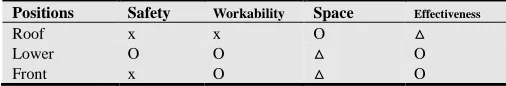
Table 2. Qualitative assessment of particle trappingdevice mounting position.
Positions Safety Workability Space Effectiveness
Roof x x O △
Lower O O △ O
Front x O △ O
O: Good, △: Normal, x: Bad
Particulate matters in tunnels settles faster than in air due to higher specific gravity, hence, capture efficiency will
increase when dust collectors are mounted lower. There are a number of advantages to mounting dust collectors at the bottom of the T (trailers) of subway trains, such as workability and space security, as well as trapping efficiency, as shown in table 2.
Although the practical size of a dust collector will depend on the installation location, multiple plate magnets should be spaced equally such that the cross-sectional area perpendicular to travel direction is at a maximum within the limits of the train dimensions [9] as shown in figure 2.
Figure 2. Structure of particle trapping device.
3. Results
Park et al. [12] reported that the concentration of particulate matters in subway tunnels in Seoul Metro increases by 9.08 µg/m3 for each subway train operating,
regardless of direction. Assuming that particulate matters dispersed in tunnels has Fe contents of 70% [3], we can calculate a corresponding increase in Fe particulate matters concentration of 6.35 µg/m3 for each subway train passing.
This particulate matters may be divided into particulates accumulated on the floor and subsequently scattered by train draft, and particulates generated through friction. If the generation rate for new particulate matter isγ
( )
≤1 , thequantity (Q) of particulate matters generated daily in a tunnel can be obtained using equation (10).
3 2
1 1
3
number of train operation each day [times/day] [ / ]where S cross sectional area of tunnel [m ]
Increased particulate matters [ g/m ] N
Q NγδS µg m day
δ µ
=
= ⋅ =
=
(10)
The operational efficiency of a dust collector depends on the ratio between the cross-sectional areas of the dust collector and the tunnel; these areas vary according to the size of the train and tunnel structure. Calculations in this study used a double-track tunnel with a cross-sectional area (S1) of 82.37 m2, and subway train with a cross-sectional area (Sc) of 13.16 m2. As the space between the train body and collector is limited to 100 mm by the structure of the subway train, the maximum cross-sectional area of a dust collector (S2) will be 3.08 m2.
When a subway train passes through a tunnel, train draft is generated both in front of the train and opposite to the
4 S S S S S c 1 2 e 2 = − = = α
If N represents the total number of daily subway train operations, M is the number of daily operations with dust collectors mounted, and c is the particulate matter concentration in the tunnel, then a quantity
particulate matter is removed, and NδS1/M
is generated per unit distance, each time a subway train dust collectors mounted is operated. Therefore, the change in particulate matter concentration in the tunnel for operational events of trains mounted with dus
be expressed by equation (12).
M / S N S c S c S
ck 1= k−1 1− k−1 2+ δ 1
µ [ 1 1 M N c c k 0 k k β β δ β − − ⋅ + = ∴ = ≥ = − = − = iron of ion concentrat initial c 1 M , M , , 2 , 1 k S S 1 1 where 0 1 2 ⋯ α β
Assuming the existence of undeposited particulate matter floating in the tunnel, an overall reduction in particulate matter concentration requires that the collector operation rate (i.e.,M/N) satisfies equation (13).
c N M c c 0 0 k δ > ⇒ <
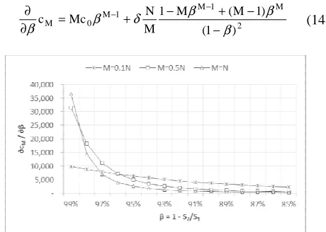
Equation (14) calculates the sensitivity of matter concentration in the tunnel to cross-sectional area of the dust collector, using
Since the particulate matter concentration in the tunnel increases with collector operation rate (i.e
decreases with the crosssectional area ratio
rate of operation and the cross-sectional area of the dust collector must be higher than the critical values if particulate matter removal efficiency is to be increased.
1 ( M 1 M N Mc c 1 M 1 M 0 M β β δ β β − + − + = ∂ ∂ − −
Figure 3. Sensitivity of particulate matters concentration to changes in
1 2 S S 1− = β . % 45 .
4 (11)
represents the total number of daily subway train is the number of daily operations with dust is the particulate matter then a quantity cS2 of Fe
) 1 (
where M ≥ M
generated per unit distance, each time a subway train with is operated. Therefore, the change in particulate matter concentration in the tunnel for k operational events of trains mounted with dust collectors can
] µg/m [ M ]
µg/m3 (12)
matters particle iron
Assuming the existence of undeposited particulate matter floating in the tunnel, an overall reduction in particulate concentration requires that the collector operation rate
S S 2 0 1 δ (13)
Equation (14) calculates the sensitivity of particulate matter concentration in the tunnel to changes in the , using Equation (12). Since the particulate matter concentration in the tunnel
operation rate (i.e., M /N ) and decreases with the crosssectional area ratio (i.e.,S2/ S1), the
sectional area of the dust collector must be higher than the critical values if particulate matter removal efficiency is to be increased.
) ) 1 M ( 2 M β β − + (14)
concentration to changes in
The cross-sectional area of the dust collector can be effectively enlarged by mounting two dust collectors with sufficient space between. Assuming that air passing through a dust collector installed at the front of a train is mixed with the air in the tunnel such that particulate matter
distributed in the tunnel, installing two dust collectors on one train should have a similar effect to operating two trains each installed with a single dust collector, as shown in
(15).
2 1 1 1
1 c S c S c
S
ck = k− − k− −β
M c
c 0
k 2 k =β +δ
∴
Assuming that particulate matter
train is not discharged outside the tunnel but remains inside, the maximum time required to remove the particulate matter accumulated in a tunnel using dust collectors can be obtained by dividing the total accumulated amount in the tunnel by the removal amount per day as shown in
S N S Mc QH D 1 2 0 − = δ Where, = = operation subway H accumulate the days of no. D
With two dust collectors installed with sufficient spacing, the time taken to remove particulate matter
decreases to 1/(1+β) compared with one dust collector, as shown in equation (17).
1 ( )
1
( + 0 2− 1 =
= S N S Mc QH D δ β
Assuming a generation rate (
the Seoul Metro of 10%, for an operational duration of 20 years, not all particulate matter
will be removed even with a dust collector of cross
area ratio 4% mounted on all trains. However, if two 4% dust collectors are mounted on all subway trains with sufficient space between, all particulate matter can be removed within 961 days.
Table 3. Removal period of Fe particulate matters
S2/S1
Dust collector (1 set) M=0.1N M=0.5N M=N
3% ∞ ∞ ∞
4% ∞ ∞ ∞
5% ∞ ∞ 16,739
6% ∞ ∞ 2,469
7% ∞ ∞ 1,333
8% ∞ ∞ 913
9% ∞ 16,739 694
10% ∞ 4,303 560
※Conditions: c0=131.6 µg/m3, δ=6.35 µ
sectional area of the dust collector can be effectively enlarged by mounting two dust collectors with sufficient space between. Assuming that air passing through a collector installed at the front of a train is mixed with the air in the tunnel such that particulate mattersare uniformly distributed in the tunnel, installing two dust collectors on one train should have a similar effect to operating two trains each a single dust collector, as shown in equation
] µg/m [ / 1 2
1S N S M
ck− + δ
] µg/m [ 1 1 M N 3 2 k 2 β β − −
⋅ (15)
Assuming that particulate matters generated by a moving train is not discharged outside the tunnel but remains inside, ired to remove the particulate matters accumulated in a tunnel using dust collectors can be obtained by dividing the total accumulated amount in the tunnel by the removal amount per day as shown in equation (16).
] day [ 1 S N S Mc H 1 2 0 − = δ γ
, (16)
[day] period operation removed are PMs d accumulate
With two dust collectors installed with sufficient spacing, the time taken to remove particulate matters in the tunnel ) compared with one dust collector, as
] day [ 1 ) 1 1 2 0 − + S N S Mc H δ β γ (17)
Assuming a generation rate (γ) of Fe particulate matters in the Seoul Metro of 10%, for an operational duration of 20 years, not all particulate matters accumulated in the tunnel will be removed even with a dust collector of cross-sectional ounted on all trains. However, if two 4% dust collectors are mounted on all subway trains with sufficient space between, all particulate matter can be removed within
particulate matters from tunnels (unit: day).
Dust collector (2 sets) M=N M=0.1N M=0.5N M=N
∞ ∞ 2,674
∞ ∞ 961
16,739 ∞ 60,312 588
2,469 ∞ 2,917 425
1,333 ∞ 1,502 334
∞ 1,015 275
∞ 769 234
∞ 620 204
International Journal of Environmental Monitoring and Analysis 2015; 3(1): 1-6 5
Since not all accumulated Feparticulate matters will be floated by train drafts after accumulated in the tunnel is removed, the concentration of particulate matters in the tunnel will increase by γδ each time a subway train operates. Therefore, particulate matter concentrations in a tunnel can be obtained by equation (18), by again considering the number of operations k of subway trains mounted with dust collectors.
],
µg/m [ 1 1 M N c
c 3
k
0 k
k
β
β
γδ
β
− − +
= (18)
Where,k=1,2,⋯,M, M≥1.
The number of dust collectors may be reduced after particulate matters accumulated in the tunnel is removed as long as equation (19) is satisfied.
2 0
1 0
S c
S N M c
ck < ⇒ > γδ (19)
In this case, the particulate matter concentrations in a tunnel decreases to equation (20) with increasing number of operation days of subway trains mounted with dust collectors. As a result, particulate matter concentrations in the entire tunnel will decrease to c0−cf .
2 1 S S
M N
cf =γδ⋅ ⋅ (20)
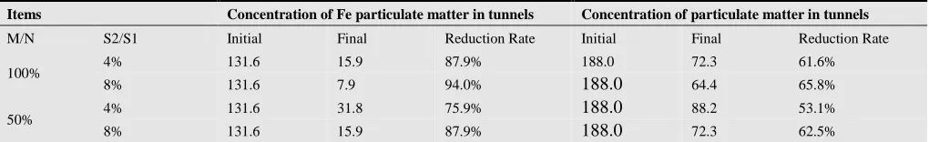
Once all accumulated Fe particulate matters are removed from the subways in Seoul Metro, the concentration of Feparticulate matters in tunnels will decrease from 131.6 µg/m3 to 15.9 µg/m3,even when all subway trains are mounted with only one dust collector with a 4% cross-sectional area. This amounts to a 61.6% reduction in particulates in tunnels. If a dust collector is installed on 50% of all subway trains, Fe particulate matters will decrease from 131.6 µg/m3 to 31.8 µg/m3, a 53.1% reduction in particulates in tunnels.
Table 4. Changes in particulate matter concentrations in tunnelsusing dust collectorsafter all accumulated particulate matters are removed.
Items Concentration of Fe particulate matter in tunnels Concentration of particulate matter in tunnels
M/N S2/S1 Initial Final Reduction Rate Initial Final Reduction Rate
100% 4% 131.6 15.9 87.9% 188.0 72.3 61.6%
8% 131.6 7.9 94.0% 188.0 64.4 65.8%
50% 4% 131.6 31.8 75.9% 188.0 88.2 53.1%
8% 131.6 15.9 87.9% 188.0 72.3 62.5%
4. Conclusion
Particulate matter is being generated continuously in subway tunnels through abrasion between wheels, rails and brake disks as well as from sparks generated during contact between electric carlines and the pantograph during subway operation. Since high concentrations of particulate matter in tunnels are dispersed by train drafts throughout the underground space, particulate matter generated in tunnels is the main source of particulates in the subway environment. Highdensity Fe particles are rapidly deposited and thus accumulate in tunnels as subway train operation increases. Particulate matter accumulated in tunnels not only pollutes the subway environment but also results in malfunction and shortened life span of the electronic devices used to control trains and equipment. It is therefore vitally important to remove particulate matter to improve air quality in underground stations.
This study proposed a method for efficient removal of particulate matter in tunnels, involving magnetic dust collectors mounted underneath operating subway trains. A mathematical model was presented to determine the design and operation of these dust collectors.
For a dust collector to effectively adsorb and remove particulate matter floating in tunnels, it should be designed so that the magnet width in the dust collector is greater than the dispersion distance of particulate matter due to train drafts. For a dust collector mounted underneath a subway train
moving at a maximum velocity of 80 km/h, the width of the magnet must be at least 16.4 mm if all particulate matter of 2.5 µm diameter or larger is to be adsorbed.
It is recommended that magnetic dust collectors be installed underneath subway trains. The removal period for particulate matter currently accumulated in tunnels may be reduced by installing two dust collectors with the maximum space between them on all operating subway trains.
After the particulate matter accumulated in tunnels is removed, it is expected that the overall concentration of particulate matter in tunnels can be reduced by 53.1% (75.9% of Fe particulate matter), even when dust collectors are installed on only 50% of all subway trains.
Acknowledgements
The work described in this paper was supported by research grants on the Railway Technology Research Project by Minister of Land, Infrastructure and Transport (14RTRP-B081249-01).
References
[1] Seoul City Government,“The status of public transport”, http://traffic.seoul.go.kr, accessed on Aug. 16, 2014.
[3] S.N. Kang, H.J. Hwang el al, “Chemical Compositions of Subway Particles in Seoul, Korea Determined by a Quantitative Single Particle Analysis”, Environ. Sci. Technol., 2008, 42 (24), pp 9051–9057.
[4] J.H. Park, J.C. Park, S.J. Eum,“The Estimation of the Diffusion Direction and Velocity of PM10 in a Subway Station - For the Gaehwasan Station of Subway Line 5 in Seoul”, J. Korean Society of Transportation Research, 2010, 19(3), pp. 35-47. [5] Seoul Metropolitan Rapid Transit Corporation,“Green Car 3
guys will shoulder the responsibility of SMRT's tunnels”, appeared at the 34th Seoul Affiliated Organization Conference for best practices of customer satisfaction and innovative management, 2010.
[6] Achieved at http://www.imstrading.com/magnet-formula.html.
[7] Achieved at
http://en.wikipedia.org/wiki/Force_between_magnets.
[8] Scott A. Shearer and Jeremy R. Hudson, “Fluid Mechanics: Stokes’ Law and Viscosity”, Measurement Laboratory No. 3. [9] Y.B. Choo, Y.O. Moon, el al, “The discussion of the standard
cross-section of the railway tunnel”, YOOSHIN Technology Newsletter, 12, pp. 134-143.
[10] J.Y. Kim, K.Y. Kim,“Experimental and numerical analyses of train-induced unsteady tunnel flow in subway”, Tunnelling and Underground Space Technology, 2007, 22(2), 166-172. [11] S.D. Kim, J.H. Song, H.G. Lee (2004): The Estimation of
train-induced wind by Train Operation in Subway Tunnel, Air Conditioning and Refrigeration Engineering Dissertation, 16, 7652-7657.