GENERIC RADAR MODELLING
by
Andrew Stuart Lilly
A thesis submitted to the University of London for the Degree of Doctor of Philosophy in Electronic Engineering
UCL
Department of Electronic & Electrical Engineering
U N IV E R S ITY COLLEGE LONDON
January 2000
ProQuest Number: U643966
All rights reserved
INFORMATION TO ALL USERS
The quality of this reproduction is dependent upon the quality of the copy submitted. In the unlikely event that the author did not send a complete manuscript and there are missing pages, these will be noted. Also, if material had to be removed,
a note will indicate the deletion.
uest.
ProQuest U643966
Published by ProQuest LLC(2016). Copyright of the Dissertation is held by the Author. All rights reserved.
This work is protected against unauthorized copying under Title 17, United States Code. Microform Edition © ProQuest LLC.
ProQuest LLC
789 East Eisenhower Parkway P.O. Box 1346
T his th esis is dedicated to the m em ory o f m y father M alcolm D ou g la s L illy, Professor o f B io ch em ical E ngineering at U niversity C o lleg e London, w ho died on 18th M ay 1998, at hom e surrounded by his lov in g fam ily.
Generic Radar Modelling 3 o f 274
A
b s t r a c t
A novel radar modelling Framework and its associated innovative modelling techniques are described. The Framework provides generic techniques for modelling a wide variety of radars, radar environments and scenarios, using a flexible object-oriented approach. It addresses many of the shortfalls of current radar models and provides a foundation for efficient radar model developments in the longer term.
The history of radar modelling is briefly described and current commercially available radar modelling packages are evaluated. Having determined the need for a more generic modelling approach, the objectives for the Framework (modular, hierarchical, reusable) are established. The basic Framework principles are determined by reference to the radar equation. The Framework decomposes a radar model into component blocks, at a level that gives flexibility without requiring an excessively deep hierarchy of blocks. The Framework defines the special data bus structure used to link blocks to form a radar simulation.
A review of simulation acceleration techniques leads to the novel concept of M ixed Mode Modelling, wherein parts of a radar model can be simulated to differing levels of detail, to optimise simulation performance without unduly compromising accuracy.
The Framework is applied to the simulation of a multifunction radar to evaluate and prove the Framework principles. This simulation is adapted to use M ixed Mode Modelling to determine its performance benefits. The simulation is further enhanced to create a detailed model of a naval phased array radar which is exercised using various engagement scenarios. This model is intended to aid in defining key design details such as signal processing and energy management strategies.
Results from these radar models are used to confirm and support the generic radar modelling techniques presented. Conclusions are drawn as to the value of the Framework for future radar modelling programmes and potential areas for future development and enhancement are identified.
A
c k n o w l e d g e m e n t s
I am especially grateful to my supervisor Dr. Paul Brennan, who has aided and encouraged me over the years as my PhD has developed from a few simple concepts into a detailed Framework.
My gratitude also to Prof. Hugh Griffiths whose active interest in this project has helped guide it towards its successful conclusion.
This programme would not have been possible without the support and guidance of Kevin Kelly (Radio Technology Prime at Nortel Networks, Harlow) to whom I am deeply grateful. The latter half of the project was undertaken in close co-operation with my colleague Geoff Brown, to whom I am greatly indebted for his dedication and hard work.
I am also grateful to DERA Portsdown West for allowing this work to be used for my thesis. Over the last few years, I have been especially thankful for the friendliness and good humour of the Combat Systems and Signature Control group at Portsdown West, including Pat Donnelly, Andy Horseman and Bill Dawber. I am grateful to Dave Money for having faith in my original concept. In particular, my heartfelt thanks to Ian Nichols, who is using the Framework ‘in anger’ and has provided a great deal of valuable feedback during its development and the completion of this thesis.
I would also like to thank all those in the Radio Technology programme unit at Nortel Networks in Harlow, whom I have consulted and/or pestered in the furtherance o f this work.
I would like to thank my mother and father for pointing me towards a career in engineering and for their encouragement to undertake this thesis. Unfortunately my father did not survive long enough to see its completion, but he is with us in spirit.
Lastly, but most importantly, my thanks to my wife Sarah who has supported me wholeheartedly throughout this endeavour and without whom this thesis would never have been completed.
Generic Radar Modelling 5 o f 274
C
o n t e n t s
Ab s t r a c t... 3
Ac k n o w l e d g e m e n t s...4
Co n t e n t s... 5
Li s t o f Fi g u r e s... 11
L i s t o f T a b l e s ...1 6 Li s t o f Pr i n c i p a l De f i n i t i o n s... 1 8 Li s t o f Ab b r e v i a t i o n s... 2 0 1 In t r o d u c t i o n... 2 3 1.1 The Development of R ad a r... 23
1.2 The P roblem ... 24
1.3 The Solution... 25
1.4 O bjectives...26
1.5 Structure of the Thesis...29
2 Ex i s t i n g Ra d a r Mo d e l l i n g So f t w a r e...3 0 2.1 Fellow M odellers... 30
2.2 Commercial Radar Modelling Software... 31
2.3 Commercial Systems M odelling Software... 33
2.4 C onclusions... 35
3 Ra d a r Pr i n c i p l e s...3 6
3.1 B a sic s... 36
3.2 The Radar Equation... 38
3.2.1 Multistatic Radar... 39
3.3 Radar R eturns... 40
3.4 D etection...41
3.5 Processing... 42
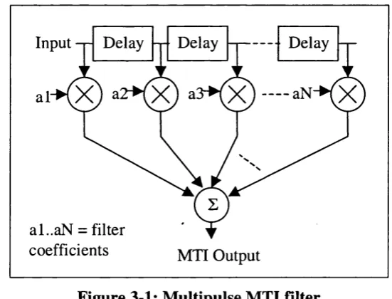
3.5.1 Moving Target Indicator...43
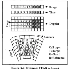
3.5.2 Constant False Alarm R a te ... 43
3.6 Target T racking...45
3.7 Ambiguity D iagram s... 46
3.8 Propagation... 49
3.8.1 Lobing... 50
3.8.2 Diffraction...52
3.8.3 Refraction...52
3.8.4 M ultipath...53
3.9 Clutter... 53
3.10 Electronic W arfare... 55
3.11 Phased Arrays... 56
3.12 Multifunction Radars...60
4 Ke y Co n s i d e r a t i o n s... 6 2 4.1 Basic Principles... 62
4.2 Modelling the Radar E quation ... 67
4.3 The Advantages of a Modular A pproach...67
4.4 B locks...6 8 4.5 Interfaces... 70
4.6 Connecting B lo ck s...73
4.7 Sample Rates and Mixed Mode M odelling... 79
Generic Radar M odelling 7 o f 274
5 Th e Ge n e r i c Ra d a r Mo d e l l i n g Fr a m e w o r k... 8 0
5.1 Basic Principles... 80
5.2 Simulation B locks...80
5.3 The Framework E nvironm ent... ...82
5.4 Framework Im plem entation... 84
5.5 The GRM B u s ... 87
6 Ex a m p l e Im p l e m e n t a t i o n...9 1 6.1 Example SPW Radar M o d el... 91
6.2 Example GRM Framework M odel... 95
6.2.1 Description of the Simulation B locks...97
6.2.2 Detail of the Transmit Antenna B lock... 102
6.2.3 Selected Results from the Example Radar M o d el... 104
6.2.4 Conclusions... I l l 7 Sim u l a t i o n Ac c e l e r a t i o n... 1 1 2 7.1 Introduction... 112
7.2 Evaluation M ethods... 113
7.3 Software C onsiderations...114
7.4 Acceleration Options... 114
7.4.1 Single W orkstation... 115
7.4.2 Single DSP processor...115
7.4.3 Concurrent Processing... 115
7.4.4 Software support... 116
7.4.5 Coding algorithms... 117
7.5 Single-Processor Solutions... 118
7.5.1 Sun W orkstations... 118
7.5.2 Sky Computers... 118
7.5.3 PC-based DSP B o ard s... 119
7.5.4 Atlantic Aerospace B la z e r...120
7.5.5 Sum m ary... 120
7.6 Multiple Processor Solutions... 121
7.6.1 Multiple Unix Platform s...122
7.6.2 Sky Station H (Shamrock)... 124
7.7 C onclusions...124
8 Mi x e d Mo d e Mo d e l l i n g... 1 2 6 8.1 Introduction...126
8.2 Signal Data B locks... 128
8.3 The Regenerator... 133
8.3.1 Regeneration A ccuracy...134
8.3.2 Implementing the Regenerator...135
8.3.3 Exercising the Regenerator... 137
8.3.4 Performance Evaluation...144
8.4 Signal Analysis... 146
8.4.1 Waveform Segm entation... 148
8.4.2 Potential Analysis Techniques...150
8.4.3 Waveform Significance...156
8.4.4 Analysis Speed... 157
8.4.5 Implementing the Analyser... 158
8.4.6 Complex W avelet T ransform s...160
8.5 Conclusions...162
9 M F R Mo d e l...1 6 4 9.1 Implementation... 164
9.2 MFR Configuration/Parameters... 165
9.2.1 Primary Radar Param eters... 165
9.2.2 Waveform Generator Parameters... 167
9.2.3 Digital Pulse Compressor Parameters...168
9.2.4 Receiver Processing Param eters...168
9.2.5 Sea Clutter Param eters... 169
9.2.6 CFAR Param eters...169
9.3 Scenario 1: Surveillance... 171
9.4 Scenario 2: Range and Doppler Ambiguity... 184
9.4.1 Doppler Ambiguity T e s t...186
9.4.2 Range Ambiguity T e s t...189
Generic Radar Modelling 9 o f 274
9.5 Scenario 3: Jammer N ulling... 192
9.6 Scenario 4; Target reu se...199
9.7 C onclusions... 208
1 0 Re v ie w o f Fr a m e w o r k Pe r f o r m a n c e... 2 0 9 10.1 Performance Analysis... 209
10.1.1 G eneric... 209
10.1.2 M odular... 210
10.1.3 Hierarchical... 210
10.1.4 Mixed Mode M odelling...210
10.1.5 Platform Independent... 211
10.1. 6 Development Environm ent... 211
10.1.7 Simulation Environm ent...211
10.1.8 Block C om plexity...:... 211
10.1.9 Low M aintenance...212
10.1.10 Speed of O peration... 212
10.1.11 Code R eu se...213
10.1.12 Data Compatibility... 213
10.1.13 Block Interfacing...214
10.1.14 Future-Proofing... 214
10.2 Validation and Verification...214
10.2.1 Hierarchical Testing... 214
10.2.2 Comparison with Third Party M odels... 217
10.2.3 Test Points W ithin Sim ulations...217
10.2.4 Conclusions...225
10.3 Further Applications... 225
11 Co n c l u s i o n s a n d Fu r t h e r Wo r k...2 2 8 11.1 C onclusions... 228
11.2 Further W o rk... 230
1 2 Re f e r e n c e s... 2 3 2
1 3 Ap p e n d i x A; Do c u m e n t a t i o n Pl a n... 2 3 9
1 4 A p p e n d i x B :
GRM
L i b r a r y S o f t w a r e ...2 4 01 5 A p p e n d i x C:
GRM
B l o c k S o f t w a r e ... 2 5 11 6 Ap p e n d i x D : Ex a m p l e o f Mo d u l e Te s t i n g... 2 6 7
16.1 GRM Digital Pulse Compression (G R M D PC )... 267
16.1.1 D escription... 267
16.1.2 Test... 268
16.1.3 Results... 273
Generic Radar M odelling 11 o f 274
L
i s t
o f
F
i g u r e s
Figure 3-1: Multipulse MTI filte r...43
Figure 3-2: Example CFAR schem es... 44
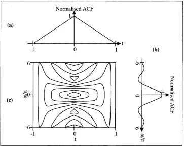
Figure 3-3: The (modulus of the) ambiguity function of a rectangular p u lse... 47
Figure 3-4: Linear FM chirp (a) amplitude and (b) instantaneous frequency with respect to radar centre frequency... 48
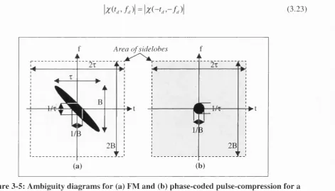
Figure 3-5: Ambiguity diagrams for (a) FM and (b) phase-coded pulse-compression for a pulse of length t and bandwidth B ...48
Figure 3-6: Radar signal reflection from a planar surface... 50
Figure 3-7: Example coverage diagram with lobing due to surface reflections... 51
Figure 3-8: Effects of refraction on radar propagation... 52
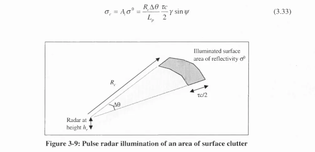
Figure 3-9: Pulse radar illumination of an area of surface clutter... 54
Figure 3-10: Beam steering using a linear array of dipole elem ents...56
Figure 3-11: Block diagram of a generic transceiver module for a phased array... 57
Figure 3-12: Array factor for 7-element array with À/2 element sp acin g... 58
Figure 3-13: Example MFR block diagram ... 61
Figure 4-1: Simple example naval radar scenario...63
Figure 4-2: Top level system configurations... 64
Figure 4-3: Subdivision of example scenario into simulation blocks...65
Figure 4-4: Expanded block diagram of example scenario... 65
Figure 4-5: Block diagram of an elementary radar sy stem ...6 6 Figure 4-6: Comparison of radar equation and block m o d e l...67
Figure 4-7: Advantages of modular sim ulation...6 8 Figure 4-8: Typical radar simulation data flow ...6 8 Figure 4-9: Example of data passing between blocks...69
Figure 4-10: Simple example block with inputs and outputs...70
Figure 4-11: Example of a parameter dependency diagram... 71
Figure 4-12: Example top level block definition (sea clu tter)...73
Figure 4-13: Possible simulation control configurations... 74
Figure 4-14: Potential connection methodologies... 76
Figure 4-15: Multiplexing of common data paths... 78
Figure 5-1: Components of a unit b lo c k ...81
Figure 5-2: Construction of a composite block... 82
Figure 5-3: Overview of simulation system ... 83
Figure 5-4: Software layer hierarchy... 84
Figure 5-5: Composition of the GRM B us...8 8 Figure 5-6: Example of data transfer via GRM B u s ... 89
Figure 6-1: Sidelobe canceller block diagram... 91
Figure 6-2: Example SPW radar m od el...92
Figure 6-3: Detail of buffer block from SLC sim ulation... 93
Figure 6-4: SLC model example results...94
Figure 6-5: Example radar m o d e l...96
Figure 6-6: Radar signal generation b lo ck ... 97
Figure 6-7: Transmit antenna blocks... 97
Figure 6-8: Antenna platform b lo ck s... 98
Figure 6-9: Receive antenna b lock s... 98
Figure 6-10: Signal processing b lo ck s...99
Figure 6-11: Internal detail of air path b lo c k ... 100
Figure 6-12: Internal detail of target b lo c k ... 101
Figure 6-13: Internal detail of jam m er b lo ck ... 101
Figure 6-14: Sea clutter blo ck... 102
Figure 6-15: Software components of the transmit antenna block... 103
Figure 6-16: Transmit antenna pseudocode... 104
Figure 6-17: Example radar scenario... 105
Figure 6-18: Results for test points 1 to 4 ...107
Figure 6-19: Results for test points 5 to 7 ...108
Figure 6-20: Results for test points 7 and 8 with adaptive antenna enabled...109
Figure 6-21 : CFAR threshold map around target...110
Figure 6-22: CFAR target detection...110
Figure 7-1: Mapping of simulation between multiple processors... 122
Figure 8-1: M ixed M ode Modelling concept ex am p le...127
Figure 8-2: Component parts of a Signal Data B lock... 129
Figure 8-3: Segmentation of simulation w aveform s... 130
Generic Radar Modelling 13 o f 274
Figure 8-4: Pulsed waveform parameters... 131
Figure 8-5: Example of combining component waveforms... 132
Figure 8-6: GRM Regenerator concept... 133
Figure 8-7: Possible Regenerator points within an example GRM radar sim ulation...133
Figure 8-8: Example waveforms generated using the GRM W aveform L ibrary... 136
Figure 8-9: Comparison of clutter generation m eth od s... 137
Figure 8-10: M ixed Mode Modelling simulation sy stem ...138
Figure 8-11: W aveform Mode signals (1)... 139
Figure 8-12: Signals regenerated from Pulse Mode signal data blocks (1)... 139
Figure 8-13: Waveform Mode signals (2)... 140
Figure 8-14: Signals regenerated from Pulse Mode signal data blocks (2)... 140
Figure 8-15: Waveform Mode signals (3)...141
Figure 8-16: Signals regenerated from Pulse Mode signal data blocks (3)... 141
Figure 8-17: W aveform Mode signals (4 a)...142
Figure 8-18:Waveform Mode signals (4b)...143
Figure 8-19: Signals regenerated from Pulse Mode signal data blocks (4)...143
Figure 8-20: Simple block diagram of example radar model... 144
Figure 8-21: M ixed Mode Modelling performance for selected simulation configurations... 145
Figure 8-22: Summary of Mixed Mode Modelling performance...146
Figure 8-23: GRM Analyser concept...146
Figure 8-24: Possible Analyser points within an example GRM radar simulation... 148
Figure 8-25: Signal analysis segmentation...149
Figure 8-26: Comparison of transform time/frequency diagram s... 154
Figure 8-27: Tree structure of discrete wavelet transform ... 154
Figure 8-28: Proposed Analyser architecture... 159
Figure 8-29: Complex DWT tree structure and resulting frequency outputs...161
Figure 9-1: Radar range and azimuth search areas...171
Figure 9-2: Scenario 1 system sim ulation... 172
Figure 9-3: Antenna gain pattern for 0° steering (dB vs. sine(theta) space)...173
Figure 9-4: Antenna gain pattern for 45° steering (dB vs. sine(theta) space)... 173
Figure 9-5: Internal detail of the adaptive antenna block...174
Figure 9-6: Detail of receiver processing blo ck ... 176
Figure 9-7: Detail of Doppler processing block...177
Figure 9-8: Radar receiver gain (noise only)... 177
Figure 9-9: Doppler map for receiver noise, short ra n g e ...180
Figure 9-10: Doppler map for receiver noise, medium ran g e... 180
Figure 9-11: Doppler map for receiver noise, long ran g e...181
Figure 9-12: Doppler map for sea clutter, short ran g e... 181
Figure 9-13: Doppler map for sea clutter, medium ran g e...182
Figure 9-14: Doppler map for sea clutter, long ran ge... 182
Figure 9-15: Scenario 2 system sim ulation...185
Figure 9-16: Doppler ambiguity scenario... 186
Figure 9-17: Doppler ambiguity resu lts... 188
Figure 9-18: Range ambiguity scenario... 189
Figure 9-19: Range ambiguity resu lts...191
Figure 9-20: Jammer nulling scenario...192
Figure 9-21: Scenario 3 system sim ulation...193
Figure 9-22: Scenario 3 - no jam m ers... 195
Figure 9-23: Scenario 3 - one jam m er...196
Figure 9-24: Scenario 3 - two jam m ers... 197
Figure 9-25: Scenario 3 - three jam m ers... 198
Figure 9-26: Target reuse scenario... 199
Figure 9-27: Target reuse scenario environment m ap...200
Figure 9-28: Scenario 4 system sim ulation... 201
Figure 9-29: Target reuse land/sea and target detection... 202
Figure 9-30: Target reuse scenario at 131 and 161 m s ...203
Figure 9-31: Target reuse scenario at 305, 509 and 614 m s ...204
Figure 9-32: Target reuse scenario at 1.0, 1,1 and 1.3 s ...205
Figure 9-33: Target reuse scenario at 1.4, 1.6 and 1.65 s ... 206
Figure 9-34: Target reuse scenario at 1.64 and 1.86 s ...207
Figure 10-1: Doppler test scenario...218
Figure 10-2: Sampled waveforms from Doppler test scen ario ... 220
Figure 10-3: Doppler CFAR threshold m ap... 222
Figure 10-4: Doppler CFAR report m ap ...222
Figure 10-5: Pulse compression test scenario... 223
Figure 10-6: Sampled waveforms from pulse compression test scenario... 224
Figure 10-7: Application of Framework principles to a communications m o d el...227
Figure 13-1: Documentation plan for the GRM Framework development program m e...239
Generic Radar Modelling 15 o f 274
Figure 16-1: Detail of GRMDPC blo ck ...268
Figure 16-2: Test simulation for GRMDPC block... 269
Figure 16-3: Chirp waveform... 273
Figure 16-4: W aveform before and after GRMDPC block ... 273
Figure 16-5: Range/Doppler raw Doppler data m ap ...274
Figure 16-6: Range/Doppler raw Doppler data (range 0-30km )... 274
Figure 16-7: Range/Doppler raw Doppler data (frequency 0 -5 k H z)... 274
L
i s t
o f
T
a b l e s
Table 5-1: Potential host platform s...85
Table 5-2: Potential host operating systems...8 6 Table 5-3: Potential host programming languages...8 6 Table 5-4: Example transmit antenna B D B ... 90
Table 6-1: Key simulation param eters... 105
Table 7-1: AT Bus DSP boards supported by SPW ’s CGS and M ultiProx...116
Table 7-2: Comparison of vector and scalar processing times...117
Table 7-3: Simulation times for Sun workstations... 118
Table 7-4: Simulation times for Sky Station I ... 119
Table 7-5: Comparison of simulation times for C40 D S P ... 120
Table 7-6: Summary of hardware accelerator op tio n s... 121
Table 7-7: MultiProx performance for various simulation configurations... 123
Table 8-1: Pulsed waveform CWB param eters... 131
Table 8-2: Comparison of analysis method speeds relative to E F T ... 158
Table 9-1: Simulation chirp param eters... 167
Table 9-2: Processing pulse/burst/waveform parameters... 168
Table 9-3: Receiver chain gain and noise power calculation (noise only)... 178
Table 9-4: False Alarm Rate reports from scenario 1 ... 183
Table 9-5: Receiver chain gain calculation (target)... 184
Table 9-6: Range ambiguity returns...190
Table 14-1: GRM Library com ponents...240
Table 16-1: Configuration file for GRMSCLUT block (clutter.cfg)... 270
Table 16-2: Configuration file for GRMDPC block (dpc.cfg)... 270
Table 16-3: Configuration file for GSUBRANT_AH block (gsubrant_ah.cfg)...270
Table 16-4: Configuration file for GRMTANT_V block (tant.cfg)...271
Table 16-5: Configuration file for GRMTGT block for Target 1 (tg tl.c fg )... 271
Table 16-6: Configuration file for GRMPOS block for Target 1 (tgtlpos.cfg)... 271
Generic Radar Modelling 17 o f 274
Table 16-7: Configuration file for GRMW AVEGEN block (w gen.cfg)... 271
Table 16-8: Parameters for GSUBDPC b lo c k ...271
Table 16-9: W aveform configuration file (w g en l.d at)...272
Table 16-10: Common simulation param eters...272
Table 16-11: Parameters for GRMPOS block for antenna... 272
Table 16-12: Parameters for GRMPTG block for antenna... 272
Table 16-13: Parameters for GRMPOS blocks for Target 1...272
Table 16-14: Parameters for GRMR ANT A A_V b lo c k ... 272
Table 16-15: Parameters for GPROCCFAR_D b lo ck ...272
Table 16-16: Parameters for GRMWAVEGEN block...272
L
i s t
o f
P
r i n c i p a l
D
e f i n i t i o n s
A number of terms used within this thesis have specific definitions within the Generic Radar M odelling Framework; to avoid confusion these terms are described below.
Block - a unit within the Framework which performs a given function (e.g. a filter) or represents a specified item (e.g. a jammer). Blocks can be “composite” or “unit”.
Compiling - the conversion of the source code, associated with one or more blocks, into the equivalent object code.
Composite block - A block constructed from one or more other blocks. These blocks may themselves be unit or composite blocks.
Development environment - the user environment within which new unit blocks are created.
(GRM) Framework - a definition of the methods by which a complete radar simulation may be constructed from a series of predefined generic blocks. The block interfaces, hierarchy, functionality and simulation environment are described using a hardware- and platform- independent approach.
Host Platform - the hardware system on which the development environment, simulation environment and simulation programs are executed. Although the two environments should have a common host platform, the simulation program might be hosted on a different platform, e.g. a dedicated simulation engine or DSP system.
Input - a value passed into a block from another block or from an external source (e.g. a data file). This term refers to values which are dependent upon an external source (other block or file) which may vary throughout the simulation, unlike a “parameter”.
Library - modules or Framework-specific functions accessible to all blocks within a simulation.
M odule - any self-contained section of software source code containing one or more procedures. Some of these procedures and associated variables may be accessible externally (i.e. to other modules) while other procedures and variables may only be used within the scope of their own module.
Object Code - the compiled version of the block source code, prior to being linked together with Library object code to form an executable simulation.
Generic Radar Modelling 19 o f 274
Output - a value passed out of a block, generally intended to become the input of another block or a “final” output, e.g. to a results file.
Parameter - data provided to a specific block that does not come via an input. Generally a fixed value (or other data) set at the start of the simulation and available only to that single block unless passed on as an output.
Signal - any type or combination of waveforms in the radar environment, whether target returns, jamming, clutter, etc.
Simulation - an executable system comprising one or more blocks.
Simulation environment - the user environment within which a simulation may be created from blocks.
Source code - a representation of a block’s functionality using a programming language or other symbolic representation.
Unit Block - An indivisible block (i.e. a block with no hierarchical sub-levels) linked directly with source code which provides the block’s functionality.
L
i s t
o f
A
b b r e v i a t i o n s
AA Adaptive Antenna
ACF Autocorrelation Function ADC Analogue to Digital Converter AEW Airborne Early W arning ARM Anti-radiation Missile ARS Advanced Radar Simulator BDB Bus Data Block
BDE Block Design Editor (part of the Alta SPW system) C The “C” computer programming language
CDF Cumulative Density Function CFAR Constant False Alarm Rate
CGS Code Generation System (part of the Alta SPW system) COMINT Communications Intelligence
CPU Central Processing Unit CW Continuous Wave
CWB Component W aveform Block CW T Component W aveform Type DAC Digital to Analogue Converter
DDE Dynamic Data Exchange (a data exchange methodology used by Microsoft Windows)
DERA Defence Evaluation & Research Agency (specifically the Combat Systems and Signature Control group at Portsdown West)
DFT Discrete Fourier Transform DOS Disk Operating System DPC Digital Pulse Compressor DSP Digital Signal Processing DW T Discrete W avelet Transform
ECCM Electronic Counter-countermeasures
G eneric Radar Modelling 21 o f 274
ECM Electronic Countermeasures ELINT Electronic Intelligence
EJ Escort Jammer
ESM Electronic Support M easures EW Electronic Warfare
EFT Fast Fourier Transform FM Frequency Modulation GRM Generic Radar Modelling GUI Graphical User Interface HF High Frequency
HMM Hidden Markov Model
HOJ Home-On Jammer
HP Hewlett-Packard HPF High Pass Filter
HPIB Hewlett-Packard Interface Bus
IDE Integrated Development Environment I/O Input/Output
IPR Intellectual Property Rights
I/Q Quadrature component representation of a signal ISAR Inverse Synthetic Aperture Radar
LNA Low Noise Amplifier LOS Line O f Sight
EPF Low Pass Filter
M ESAR M ultifunction Electronically Scanned Adaptive Radar MFR M ultifunction Radar
MFT Multiresolution Fourier Transform MSE Mean Square Error
MTI Moving Target Indicator OS Operating System OTH Over The Horizon
PAS Position Analysis System PC Personal Computer
PDF Probability Density Function PEM Parabolic Equation Model
PPI PRF PRI RAF RCS RMS RPN RSS SAR SDB SDE SLC SNR SOJ SPW
SSC STFT TCP/IP WGL
Plan Position Indicator Pulse Repetition Frequency Pulse Repetition Interval Royal Air Force
Radar Cross Section Root Mean Square Reverse Polish Notation Radar Support System Synthetic Aperture Radar Signal Data Block
Signal Design Editor (part of the Alta SPW system) Sidelobe Canceller
Signal-to-Noise Ratio Stand-off Jammers
Signal Processing Worksystem (produced by the Alta Group of Cadence Design Systems)
Statistical Signal Characterisation Short Term Fourier Transform
Transfer Control Protocol/Internet Protocol Waveform Generation Library
Introduction 23 o f 274
I
n t r o d u c t i o n
This chapter describes the background to the project, most importantly its purpose and key objectives.
1.1
The Development of Radar
It has been claimed that the introduction of radar into the Royal Air Force (RAF) in the late 1930’s led to the first systematic application of quantitative analysis to military affairst^i. In the 1920’s the military were reluctant to listen to scientists, deeming the scientific community useful only for the initial research and development of new weapons and defence systems. Following the success of radar in W orld W ar
n,
the additional value of scientific analysis was finally recognised: scientists were not merely laboratory ‘boffins’, but could advise military commanders directly how best to deploy new weapons and other military systems effectively in battle.In the 1930’s, Great Britain regarded bomber aircraft as the ultimate deterrent, threatening to unleash mass destruction on any aggressor. It became equally clear that Britain needed to be able to intercept and destroy any such attack from an enemy. However, there were no means to detect enemy bombers at a safe distance, nor to guide the fighters to them. Constant patrols of fighters around the coast would have been exceedingly inefficient and costly, but the only alternatives in 1934 were unreliable infrared systems with minimal range, and an acoustic detection system which was already obsolete due to the increased speed of enemy a irc ra ftt^ l.
Radar was developed simultaneously in several countries in the 1930’s but the threat of war in Europe motivated particularly rapid radar development in Britain. Since the first British experimental research station at Orfordness in 1935, radar has grown over 60 years to encompass a plethora of different applications. Sophisticated modem military radars are used for surveillance, navigation, weapons guidance and sensing, from land-based airborne early warning (AEW) systems to detecting buried mines. Civilian uses range from air traffic control and navigation to police radars for checking automobile speeds, astronomy, mapping of the earth’s terrain and resources, marine vessel harbour control and automobile collision avoidance. Applications such as sonar and medical ultrasonics, although using different mediums, use similar principles and signal processing methods.
Radar development continues unabated today, with advances in component and computing technologies, and the development of multifunction radars (MFRs) offering greater functionality and flexibility in a single radar system. The increasing demand for the extraction of more complex and detailed information from radar signals is the primary motivation for the development of new radar technologies such as: antenna technologies, wider radar bandwidths.
multifrequency operation and higher transmission power. There is also a desire to exploit the latest advances in signal processing techniques to give high resolution two- and three- dimensional imaging of targets or terrain, target velocity and direction estimation within the radar beam. The provision of these features requires a dramatic increase in the amount of data (typically digital) which a radar must process, usually in real time.
M odem radar systems, and the environment within which they operate, are usually physically and computationally complex and dynamic. A radar often consists of costly hardware and software subsystems which are required to interact to produce an efficient overall system behaviour which meets an operational objective. Substantial costs are involved in developing, acquiring, integrating, operating and understanding the complexities of such radar systems. In addition to initial theoretical analysist^l, these costs create the need for a software development environment which supports simulation and prototyping activities - from the functionality of individual components to the performance of the overall radar system. In addition, it is now becoming prohibitively costly to test the full performance envelope of complex modem radar systems in the field, thus performance prediction models are an integral part of a radar’s acceptance processMC^l.
1.2
The Problem
When attempting to fulfil a particular operational requirement, the radar sensor designer is typically required to develop a configuration which will meet the performance objectives with the minimum cost and risk. Frequently, the designer is faced with an enormous span of possibilities including choice of configuration (single beam, multibeam, mechanical scan, electronic scan, etc.), choice of waveform modulation (narrowband, wideband, CW, pulsed, etc.), choice of operating frequency (possibly HF through centimetric to millimetric) and choice of signal processing method and technology.
Simulations of radar performance have been used since the first years of radar development - predictions of Plan Position Indicator (PPI) output were used for the Normandy landings in
1 9 4 4[6] However, to date, radar modelling has been largely confined to models which have
explored variants upon one basic configuration in support of particular system developments (e.g. a model of a specific radar) or more simple models in support of specialised operational assessments (e.g. models of alternative signal processing methods within a specific radar). In the extreme, a model may represent minute physical detail, e.g. simulating the returns from every hydrometeor within a virtual meteorological environment to provide a synthetic radar signal for a weather radart^h
Current methods for implementing radar models usually satisfy the requirements of the project for which they were created. However, these one-off custom creations typically also suffer a number of significant drawbacks:
• Little or no reuse of code from preceding radar models.
• Incompatibility with the code, methods and data of previous (and future) radar models. • The entire radar model must be tested from scratch.
• Time constraints usually preclude the use of modular code, such that the model is more difficult to debug, validate and verify.
Introduction 25 o f 274
Resulting simulations are inflexible with a short lifetime and are difficult to maintain.
Time constraints may lead to the use of third-party code/routines which are often difficult to maintain and restricted in use due to intellectual property rights (IPR) considerations.
An investigation of commercially available radar modelling software was undertaken at the outset of this work; it indicated that these problems have not, as yet, been solved. Such commercial models either tend to concentrate on one specific aspect of the radar - and are thus of fairly limited use - or attempt to model the overall radar system, but are too inflexible and/or simplistic to be of genuine use for a wide range of tasks. The commercially available programs also tend to be quite complex, both in their use and the interpretation of their results. None of the software analysed has the features necessary for a truly generic radar modelling system.
Analysis of a large number of software-oriented projectst^l indicates that an initial investment in a more generic approach to the creation of software models has significant long term advantages. For example, a modular approach would typically allow a new model to be quickly constructed from the code modules of previous simulations, removing the need to write, debug and validate code modules other than those created specifically for the new model. This approach promises faster development of new radar models with corresponding savings in time and money.
W hile a custom software model could allow initial determination of a given radar’s requirements and any novel signal processing involved, a truly flexible model would allow the evaluation of that radar using the characteristics (and limitations) of the real components. The generic modelling approach can thus save development time and ensure easy comparison (and thus validation) of the real implementation against the optimal radar model.
1.3
The Solution
The primary focus of this work has been to address the problems of current ‘built-from- scratch’ radar models, through the specification of a novel Generic Radar Modelling (GRM) Framework which supports software modelling of a wide range of radars and environments. In addition, features inherent in the Framework have been exploited to provide a novel modelling method: M ixed Mode Modelling. This allows a radar system to be simulated in differing levels of detail, such that the user can focus the simulation’s processing power upon those features of the model which are of particular interest, while retaining an accurate overall simulation of the radar system performance, thus optimising simulation performance.
The Framework defines the individual elements or groups of elements from which a radar system can be constructed, and the manner in which these elements may be connected to create an executable simulation. The Framework describes the modelling methodologies to be used and the environment(s) required to support the simulation system, while avoiding reference to any particular application, platform or programming language, in order that these choices can be made by the user to best match their available resources and skills. The Framework uses a structured object-encapsulation approach but does not assume the use of a specific object- oriented programming language. The Framework is intended to be sufficiently flexible to allow it to be extended during its intended lifetime without requiring re-design of existing Framework blocks and simulations.
W hile the described Framework has remained intentionally generic with regard to the radar type, scenario and simulation platform, each aspect of the Framework has been analysed to determine possible implementation methods and thus to ensure that its realisation as a usable modelling system is practicable. To demonstrate and exercise the Framework principles, several example radar models were created during the course of this work. The results of simulations using these models are presented and discussed in this thesis. A number of platforms and languages were compared to ascertain those which were deemed most suitable for this programme.
1.4
Objectives
The objective of this work was to develop a generic radar modelling system. Having determined that no such system already existed, the requirements for such a system were investigated. A Framework to address the requirements was proposed and an example radar model was used to exercise and prove the Framework principles. This simulation was implemented as a detailed time domain model but could be simplified to use statistical modelling. The Framework also lends itself to implementing a system mixing these two modelling methods. Having built such a Mixed Mode M odelling system, its performance was compared to the former time domain model. Finally, a more detailed simulation of a multifunction radar (MFR) was implemented, demonstrating the level of modelling detail which can be generated without compromising the objectives of the generic radar modelling system.
This work was undertaken at Nortel Networks Harlow Laboratories for DERA Portsdown West, in two phases between 1994 and 1998. A summary of the associated project documentation is given in Appendix A.
A challenging set of objectives were set down at the start of the projectt^in^k The Framework has been developed to address these objectives as closely as possible. The conclusions to this thesis discuss how these objectives have been met within the limitations of the real world (time, budget, processing power, etc.). The objectives are discussed below.
Generic - The Framework should be able to handle a wide range of radars, environments, targets and jamming sources - both current and future, civilian and military. The Framework should not preclude the use of any particular radar technology, method or algorithm. The Framework should therefore be inherently capable of expansion through the addition of new user-defined functions.
Modular - Each major facet of the radar simulation should be provided in a module which encapsulates the data and functionality required of that aspect o f the simulation without relying upon global data or other such entities. This approach should give maximum flexibility in the usage of the modules within the Framework environment, increase compatibility with other simulations (e.g. through code reuse), and provide better structured code which is easier to debug, validate and verify.
Hierarchical - The Framework should provide a structured hierarchical approach where blocks may be nested within other blocks. This should permit the construction of complicated blocks from groups of other blocks, increasing the speed with which a complicated model can be
Introduction 27 o f 274
put together (using only the ‘composite’ blocks) and allowing the underlying complexity to be hidden from the user.
Mixed Mode M odelling - The Framework should support the use of blocks operating at different sampling rates and thus different processing methods (modelling modes) running within a single simulation. Such blocks could have multiple (interchangeable) forms - one for each modelling mode - or could combine the necessary functionality for several modes within a single block with the user defining their mode of operation for a given simulation.
Platform Independent - For the Framework to be of general benefit to multiple users, it must remain independent of platform, programming language and development environment.
Development Environment - In constructing new blocks for the modelling system the user requires an integrated development environment (IDE) which is simple and quick to use. Generation of a new block may consist of ‘plugging together’ pre-generated blocks (i.e. easy access to a library of such blocks is required) or may be by a ‘scratch-build’ method where the functionality of the block is defined using an existing programming language or an intermediate form of pseudocode. The benefit of having a graphical interface to this (and the simulation environment) is that people tend to understand and work easily using pictorial representations to formulate ideas.
Simulation Environment - To allow efficient Construction of a radar model from a library of predefined blocks, the user requires an integrated simulation environment which is simple and quick to use. Easy access is required to the radar block libraries and manipulation and connection of the blocks on screen should be relatively effortless, with unnecessary complexity hidden from the user. Once a simulation has been constructed the simulation environment should perform the necessary processing to generate executable code for the target machine. The IDE for the simulation environment can, in principle, be merged with that of the development environment provided this does not complicate their use.
Block Complexity - The Framework should not explicitly define the internal workings of a block (although it should define the common interfaces between blocks). The implementation of a block should be defined by the user, such that it can be replaced, simplified or upgraded at a later date. The Framework should be able to handle both simple and complex implementations of a block, anticipating the necessary interfaces for the complex version without precluding the more simple functionality, and vice versa.
Low Maintenance - The Framework, development environment, simulation environment and radar block libraries should all require minimal maintenance (debugging, third-party fees, etc.). This is largely dependent upon the choice of an appropriate long-term implementation methodology, i.e. a widely-used programming language or third-party development system. This should not preclude the use of the Framework as the basis for a simple one-off short-term simulation tool.
Speed of Operation - The Framework should not be so complex that simulation times are significantly increased from those of a model written ‘from scratch’. W hile it must be recognised that certain Framework functionality (e.g. Mixed Mode Modelling) will typically require a certain amount of processing overhead, the Framework should be designed so as to minimise such costs.
Code Reuse - The Framework should, preferably, allow the inclusion of source code and libraries from previously generated models with the minimum amount of alteration. A given implementation may have this as a specific aim, i.e. converting an existing simulation into Framework blocks. However, such considerations should not limit the functionality of the Framework. More generally, the Framework rules should aid in good ‘house-keeping’ with respect to the code and/or blocks generated for a given implementation. This should ease later modification and reuse of whole or sections of the code/blocks. The importance of configuration control for blocks should be emphasised, as with any significant software development.
Data Compatibility - The Framework should not preclude the use of any particular data source as an input or output. It is important that the Framework be able to use data from other (off-line) simulations as well as real (measured or captured) data.
Block Interfacing - The user should be able to construct simulations easily by connecting blocks using a graphical user interface (GUI) which ensures correct interfacing between blocks (i.e. adherence to the Framework input/output data types and structures).
Future-Proofing - The concept of future-proofing the Framework and, to a degree, any specific implementation of the Framework, has been implicitly covered in several of the preceding sections, particularly the generic nature, hierarchical expandability, platform independence and reusability. However, this objective is specifically stated here to emphasise the importance of ensuring that the Framework lifetime is far greater than the time-scale for modem radar developments, i.e. a lifetime of several decades rather than just a few years.
A primary aim of the GRM work is “integrated modelling”Ul], i.e. performance analysis to describe global properties of the radar system, such as sensitivity, detection range or measurement accuracy. This is not part of the more traditional structured modelling methods because the performance data emerge only from the interaction of all parts of the system, and cannot be determined using just one decomposed part of the system.
Such a model can be purely functional, in that it describes the operation of the radar system largely independently of the implementation. Combined with the performance model, resulting data can be fed into both physical models (space models, etc.) and managerial models (time- scales, budget, etc.). A suitably modular model can then be used to generate the requirements specifications (functional and performance) not only for the whole radar system but also for its component parts. This can be a significant aid in resolving the debate over whether the radar system can be implemented using off-the-shelf processing capability or requires dedicated hardwareU2].
Introduction 29 o f 274
1.5
Structure of the Thesis
Chapter 2 examines the current state of commercially available radar modelling software and determines that, as yet, a radar modelling program meeting these objectives is not commercially available.
Chapter 3 provides a primer on basic radar principles and then focuses in more detail on those aspects applicable to the example radars modelled in this thesis.
Chapter 4 examines the requirements for a radar modelling tool and describes the evolution of a modular block-based simulation tool, resulting in the GRM Framework. Chapter 5 describes the basics of this novel Framework and chapter 6 evaluates a first, relatively simple, time-
stepped radar model built using the Framework.
Given the use of Nyquist rate simulation of the radar waveforms in this example model, it is apparent that the modelling is processing intensive. Although the Framework is equally applicable to a model using only pulse-to-pulse (or lower) sampling rates with statistical detection probability, it was recognised that a means of accelerating the simulation should be investigated. Two approaches were evaluated: chapter 7 describes the analysis of acceleration opportunities using alternative host processors and parallel processing; chapter 8 examines the
novel concept of M ixed Mode Modelling, whereby only selected parts of the simulation are executed at Nyquist sample rates and the remainder are processed at a much lower rate, saving significant processing time.
To exercise and prove the Framework more completely, a complex naval MFR model was constructed. The simulation included an adaptive phased array with multiple search areas and corresponding waveform types, manoeuvring targets and jammers, atmospheric propagation and sea and land clutter. The results of this modelling are presented in chapter 9.
Chapter 10 reviews the performance of the Framework, its novel features, validation and verification, applications and limitations.
Chapter 11 draws conclusions as to the overall success of the Framework and its applicability to future radar modelling.
2
E
x i s t i n g
R
a d a r
M
o d e l l i n g
S
o f t w a r e
The automation of radar calculations began as computers first became available to scientists. Simple calculating programs were available for the early programmable calculators^!^! and, subsequently, for the first desktop personal computers (PCs). As the processing power available to scientists grew rapidly, so more detailed radar modelling became possible - from analysis of the radar waveforms to ‘wargame’ simulations of air defence scenarios. However, only now are commercially available workstations becoming sufficiently powerful that the performance of the entire radar system can be modelled within a reasonable period of time, from detailed time- sampled waveforms to the overall energy management of the radar system. The GRM Framework developed for this thesis aims to provide the radar modeller with the flexibility to create such simulations.
To ensure that such a generic framework was not already available, a detailed literature search was performed, fellow radar modellers were consulted, and a number of commercially available radar modelling products were evaluated. In addition, a variety of general block- oriented simulation programs were known to be available commercially but were aimed towards process monitoring and evaluation of simple radio and signal processing applications. These third-party tools were examined to determine their suitability as a platform for radar modelling generally and for the GRM Framework specifically.
2.1
Fellow Modellers
Discussion of radar modelling approaches with a number of knowledgeable sources^!"^!, combined with a search of current radar modelling literature, indicated that there was currently no truly generic approach to radar modelling, either in theory or in practice. A number of supposedly generic frameworks had been proposed over the years but all had suffered from significant drawbacks. For example, in addition to the problems indicated in section 1.2, the following faults were highlighted by DERA:
• Lack of documentation and support after completion of the framework - making it impossible to alter or expand the framework, or even to reuse code modules written for it. • Limitations on the usage of the framework - particularly where the framework depended
upon the use of third-party code which was badly supported, or restricted by third-party IPR considerations.
Investigation of related disciplines (through a literature search) indicated that some object- oriented modelling work was underway in other fields (e.g. electro-optical devicest!^!, underwater systems^^G, air defence^!^] and battle tanksHS]). However, such sources were often
Existing Radar Modelling Software 31 o f 274
reticent about discussing their work, given its commercially (or militarily) sensitive nature. In general, such projects involved a Graphical User Interface (GUI) for linking together icons representing components of the modelled system.
Some details of specific models have been extracted from the literature - sufficient to determine that they are not truly generic radar modelling tools. For example, Racal Radar Defence Systems’ RAPPORT, ARS and SPSim tools[^ltl9] provide, respectively: detection probability based upon a complex radar equation (with a range of noise and clutter models); simulation of the complex (I and Q) outputs from a radar receiver; simulation of the signal and data processing algorithms for the Searchwater 2000 radar system. A complex Signal Path Model (SPM)[5] was created for the Australian Jindalee over-the-horizon (OTH) radar which featured a block-oriented approach for some parts of the radar system. The Radar Support System (RSS)t^k2 0j and the associated Position Analysis System (PAS) for the military
Firefinder radad^^l are software tools intended to assist in the siting and performance evaluation of a range of radars, based upon a detailed database of the local terrain (whether an airport layout or a battlefield). The aim of a generic radar modelling framework is to enable all these aspects to be simulated within a common radar model. In addition, the block-oriented GRM Framework advocated in this thesis provides a direct means of modelling and thus verifying the individual sub-systems of the radar hardware as they become available.
More recently, some designers have recognised the limitations of existing radar models and have begun to attempt to address this problem, by amalgamating and standardising radar programmes within user-friendly environments (running within the Windows operating system on commonly-available PC platforms)[22]. The approach taken by the Alenia Defence - Radar System Division uses a variety of programming languages (C, Visual Basic) and third-party tools (from Microsoft Excel spreadsheets to M athCAD’s mathematical tools) to provide a user- friendly display interface for a series of radar models handling both real and simulated radar data. However, despite some adaptability, this still does not have the full flexibility of a truly generic radar model. Further, the model does not appear to provide any special features that could not be implemented using a truly generic radar modelling framework.
2.2
Commercial Radar Modelling Software
This section gives a brief analysis of the main radar modelling products currently available commercially. All the products were examined and evaluated by the author. None of the products provides a truly generic radar modelling capability, none can provide detailed time domain modelling of the radar signals, and none support user alterations or extensions to their basic functionality.
M odern Radar System Analysis Software
This modelling software by David and William Bartont^B] allows the user to enter a fairly comprehensive set of parameters for the radar model, targets, environment, jamming and detection model. It provides extensive numerical and graphical outputs but suffers from a poor, outdated user interface which requires a high degree of expertise by the user to understand the relationships between the entered data and the results. The program is inflexible, having a fixed set of modelling methods which the user cannot alter or extend. Further, the software can only model the top level system statistics and has no provision for modelling component-level
parameters, transients and other time domain events. Data input is via textual screen prompts, with no textual or graphical indication of the functional flow of the radar system.
The manual provides a useful description of the equations and methods used by the software but relationships between different parts o f the program are not clearly defined, nor does Barton’s corresponding text bookt^^l address these issues; presumably the user is expected to be proficient in the field of radar modelling.
CARPET
The Computer-Aided Radar Performance Evalation Tool by Huizing and Theilt^S] a fairly user-friendly software package which models a supposedly generic radar system. The program provides clear, concise and useful graphical output (received powers, detection probabilities, blind spots, vertical coverage. Moving Target Indicator (MTI) improvement, antenna patterns, etc.) and its manual explains clearly the program’s methodology (the radar equations used, assumptions made, etc.). However, the ‘generic’ system modelled by the software is limited to a statistical simulation of a single transmitter/receiver system, with certain combinations of clutter, targets, noise, jammers, etc. For example, this precludes the modelling of a bistatic system, or of a combination of several different types o f target and jammer.
Unfortunately, CARPET suffers many of the limitations of B arton’s software, allowing modelling only at the system level with no facility for modelling a dynamic environment, no capability to simulate detailed time domain responses and no method by which the user can modify its underlying principles and algorithms.
RGCALC
The Radar Range Detection S o f t w a r e [26] (RGCALC) is a re-written version of a Fortran
program created by L.V. Blake of the Naval Research Laboratory, W ashington D C. The program uses a simple textual input to perform statistical detection range calculations and provides simple textual output. A listing of the source code is provided in the manual, with a short description of the algorithms used. This software’s very specific purpose makes its usage very limited compared even to the other modelling packages considered in this section.
DETPROB
The Probability of Detection Calculation Software by Skillmant^V] allows the calculation (and plotting) of radar detection probability for a wide variety of radar parameters. Input and output is by fairly simple textual prompts and displays but the manual does describe the program’s functionality in detail, with a full listing of the source code. However, the program’s very specific purpose limits its usage such that it is no more a ‘generic’ tool than is RGCALC.
Surface-Based Air Defense
This suite of programs by M acfadzean and Johnsont^S] provide high-level modelling of tracking and engagement of targets by ground-based weapons systems. Radar plays only a small part in the calculations and is modelled at a simple level. However, this suite indicates some of the potential of a generic radar modelling package, whether used to provide statistical radar performance data, or for modelling actual radar functionality in the dynamic scenarios supported
Existing Radar Modelling Software____________________________33 o f 274
by the suite. The programs suffer the constraints of the other packages considered here in that there is no facility for the user to extend or alter their modelling capabilities.
2.3
Commercial Systems Modelling Software
The following modelling systems were evaluated to determine if they could provide a suitable level of radar modelling as part of their normal function, and/or whether they could be adapted for use as a graphical front-end for the GRM Framework. None of the products provided a generic radar modelling capability, although several were considered suitable for adaptation as a GUI for the GRM Framework.
H P Vee
Hewlett-Packard designed this product primarily to provide a user-friendly method for programming and controlling equipment over HPIB links. The software uses a GUI with function block icons linked by ‘wires’ to show program execution flow. Simple flow control blocks {if...then, case, etc.) are provided with a range of input and output facilities. Blocks can be nested to form a hierarchical system. However, the libraries lack many mathematical functions and user source code cannot be embedded directly into blocks, although a block may call an external program, passing it values and retrieving the results. The ‘call’ may be to execute a program directly or via a data link philosophy: dynamic data exchange (DDE) under Windows on a PC, or pipes/sockets on a Unix machine. It appears that the overall control program cannot be run as a standalone executable, but must be run within the HP Vee environment. Overall, HP Vee does not provide the functionality required for a generic radar modelling environment.
Signal Processing Worksystem
Produced by the Alta Group of Cadence Design Systems, Inc., SPW is a dedicated systems design and modelling package, aimed primarily at the communications market but with add-on libraries for radar, mobile communications and similar key areas. It has the capability to produce standalone executable code for both the host platform and a number of digital signal processing (DSP) devices.
SPW provides a hierarchical, modular basis with a wide range of signal sources, DSP functions and analysis tools, as well as a library of radar functions. It has a user-friendly GUI, runs on Sun and Hewlett-Packard workstations and, at the outset of this thesis, was already in use by those parties interested in the development of the GRM Framework (Nortel Networks and DERA Portsdown). SPW combines a block development environment and a simulation environment (as defined in section 1.4) in a single package, while allowing the complexity of the block development to be hidden from the general user if desired. SPW incorporates the source code from user and predefined blocks into a single source code file which can then be compiled on the target platform. SPW predominantly uses C for its source code which is a significant advantage, given the wide usage of C as a programming language for existing radar models.
SPW is widely used by a number of major firms[2^1[30][31]^ including Nortel Networks, Texas Instruments, Ericsson, Siemens, GEC Marconi and BT Laboratories. Alta Group have indicated its potential for use in radar modelling[32] but this has not been fully exploited to date.
Simulink
Produced by The M athW orks Inc., this D ynam ic System Sim ulation Softw are is an optional add-on to their Mat lab m athem atical m od ellin g package. A sim ple G UI a llo w s the linking o f functional b locks to produce a m odel w hich can then be ex ecu ted from w ithin Sim ulink. B lock s can have user-defined source cod e em bedded into them , u sing the M atlab “M file ” language, or C cod e. B lock s can also be nested to som e degree. A lthough sim ilar to other packages (e.g. S y stem V iew ), S im ulink has the advantage o f easy access to the ex ten siv e M atlab libraries o f m athem atical functions. Further, it has som e features (such as dynam ically flex ib le input and output vector size to som e b lock s) w hich even dedicated to ols (e.g. S P W ) do not provide. H ow ever, S im ulink d oes not com e with a supported radar library, nor is the G U I as advanced as its com petitors (e.g. SPW ).
SystemView
Produced by E lanix Inc. and distributed in the U K by Entegra Lim ited, S y stem V ie w provides a sim p le GUI for m anipulating and linking together functional blocks to create a system m odel. O ptional libraries include com m u nication s, log ic, D S P and radio frequency (R F )/analogue functions and com ponents. B lock s can be nested to form “M etaS ystem s” . U ser source cod e can be em bedded into blocks using an additional library. In summary, this m o d ellin g package provides a cheap alternative to a system such as SPW , or a dedicated RF m o d ellin g package such as O m nisys. H ow ever, it appears less flex ib le than the former, and less refined (in interface and usage) than the latter.
SMOOCHES
State M achines for O bject-O riented Concurrent, Hierarchical E ngineering S p ecifica tio n s is a m od elling system based on hierarchical state m achines and exten sion s to state charts. The system is intended to m odel distributed reactive system s, using a high level ob ject-oriented specification language. SM O O C H E S sim ulations m odel the interactions betw een the hardware and softw are subsystem s to create a m odel o f the overall system .
It is encouraging that SM O O C H E S advocates the sam e object-oriented tech niq ues esp ou sed for the G RM Framework: softw are reuse is enhanced w hen object-oriented tech niq ues are applied efficien tly in defining the system objects; objects in the system can be defin ed in clo se correspondence to real-w orld objects; the rapid develop m en t o f new softw are is prom oted; the use o f inheritance enables the creation o f new objects and associated m ethods with m inim al effort; the use o f encapsulation provides the appropriate distinction betw een object boundaries and is effective in identifying and con trollin g the propagation o f errors. From a practical point o f view , supporting object-oriented techniques for system s develop m en t en ab les e ffec tiv e softw are m anagem ent and revision control in the softw are evolu tion process.
Barcio uses SM O O C H E S to m odel a notional air d efence system U^j. H is reasoning is that this exem p lifies a system with the fo llo w in g characteristics: it in v o lv es significant interaction betw een softw are, hardware and human users (operators make initial d ecisio n s regarding tracking targets and en gaging w eapons); it requires a predictable response from a dynam ic, uncertain environm ent (the radar m ust react predictably when tracking the target, although the target and the environm ent are dynam ic and external to the radar); it has m ultiple interacting subsystem s and environm ental constraints. SM O O C H E S uses a fairly abstract level o f