© Penerbit UTHM
DOI: https://doi.org/10.30880/ijie.2018.10.05.013
Challenges in Fabricating Solid Oxide Fuel Cell Stacks for
Portable Applications: A Short Review
Nor Fatina Raduwan
1, Andanastuti Muchtar
1,2,*, Mahendra Rao Somalu
1, Nurul
Akidah Baharuddin
1, Muhammed Ali SA
11
Fuel Cell Institute, Universiti Kebangsaan Malaysia, 43600 UKM Bangi, Selangor Darul Ehsan, MALAYSIA
2
Centre of Materials Engineering and Smart Manufacturing (MERCU), Faculty of Engineering and Built Environment, 43600 UKM Bangi, Selangor Darul Ehsan, MALAYSIA
Received 25 July 2018; accepted 27 August 2018, available online 30 October 2018
1. Introduction
Due to depletion of fossil fuels and growing demand of energy consumption, there has been considerable research efforts on developing alternative sources of energy such as biomass, solar, wind and hydrogen [1]. One type of hydrogen energy which is solid oxide fuel cells (SOFCs) were first developed by Gaugain after the discovery of solid electrolytes in 1853. During the 19th century, SOFCs were actively developed. Nernst showed that 15mol% yttria-stabilized zirconia (15YSZ) exhibits high conductivity, and Schotty later proposed that it can be a potential candidate for solid electrolytes. Baur and Presis further proved that YSZ works at 1000 °C [2]. Several
studies used ceramic oxide as the electrolyte and fabricated stacks with various designs to improve its performance. Compared with other types of fuel cells, such as proton-exchange membrane fuel cells (PEMFCs), direct-methanol fuel cells (DMFCs), alkaline fuel cells (AFCs), molten-carbonate fuel cells, and phosphoric acid fuel cells, SOFCs feature a higher efficiency of up to 90% if the heat produced is harnessed and the anode off-gas is recycled to the anode inlet [3] (Figure 1). The relatively high operating temperature of SOFCs allows internal reforming and enhances the kinetics reaction. Moreover, SOFCs can tolerate fuel impurities because of their high operating
Abstract: Despite being the most efficient and quiet operation type of fuel cells, solid oxide fuel cells (SOFCs) deal with several constraints in terms of fabrication cost, material selection and durability issues due to their high operating temperature. The high operating temperature of SOFCs limits their stationary and large-scale applications. Moreover, these constraints restrict the commercialization of portable SOFCs. Therefore, the operation temperature of SOFCs must be reduced to overcome the aforementioned problems. However, this task is challenging because the operation temperature mainly affects the material preparation and the stack design to produce the electrical power needed for small-scale applications. This paper provides an overview of the challenges faced by each component such as the materials, the design of stack, fabrication cost and related research in fabricating high power SOFC stacks.
Keywords: Solid oxide fuel cell, stacks, materials, cost, portable applications
temperature [4]. Therefore, SOFCs are flexible to many types of fuels and not limited to pure hydrogen [5]. A single cell consists of three main components, namely, anode, electrolyte, and cathode [6]. Fuel is supplied at the anode and air at the cathode. At the cathode, oxygen in air is reduced to produce oxygen ions that pass through the electrolyte into the anode. The oxygen ions that reach the anode react with fuel, leading to oxidation. Consequently, electrons are released into the outer circuit and water as the by-product [7]. The basic working principle of SOFCs is shown in Figure 2.
Fig. 2 Basic working principle of SOFCs.
A stack is formed by combining a number of single cells sandwiched by interconnect materials as a current collector. All components must be compatible to prepare a working stack. SOFC stacks have two types, namely, planar and tubular. The planar design has excellent power density because of its effective current collection and low cost fabrication, whereas the tubular design features outstanding mechanical and thermal properties [8]. Due to its capability to operate in high temperature, SOFCs are most likely to be applied by large-scale, stationary applications with power ratings up to megawatt [9]. Over the years, small-scale energy delivering devices (1–20 W) had a spring up need for power sources in portable electronic devices [10]. With the progress in thin film technology and microfabrication, micro-SOFCs are predicted to be developed as battery replacement in small devices [11]. Compared with PEMFCs and DMFCs, micro-SOFCs are foreseen to have better performance in term of specific energy and energy density output. For instance, eZelleron, an innovative company developed a 1–100 W prototype microtubular portable devices. Meanwhile, Ultra Electronics-USSI designed and manufactured SOFC for back up and portable power generation. Their tubular ceramic cell design allows them to offer compact and rugged systems that can operate in the most austere and remote locations. [12]. Figure 3 shows the results of a literature survey on the number of publications about the development of SOFC stacks. These data were obtained by searching the ScienceDirect database for “SOFC,” “stack,” “planar,” and “tubular.” The data demonstrate the ongoing interest in the development of SOFC stacks.
2.
Material Challenges
Given that SOFCs operate at a high temperature, not all materials are suitable to meet the purpose, and interconnect materials are costly. This major drawback has brought the attention of researchers to lower the operating temperature (<1000 °C). Thus, a new operating temperature zone called intermediate-to-low temperature (LTSOFC) zone was proposed [13]. A typical IT-SOFC operates below 800 °C, and LT-IT-SOFCs operate below 600 °C [14]. The electrical and catalytic activity, chemical compatibility, and thermal stability of materials should be adjusted to allow SOFC components to operate in a low temperature range.
2.1
Anode
Fuel oxidation takes place at the anode, as shown in Figure 2. In consideration that gas exchange occurs at the gas–electrolyte–anode interface, the anode should have sufficient porosity. Nickel/yttria-stabilized zirconia (Ni/YSZ) has been used for a long time as anode materials and shows excellent performance at high operating temperatures. However, Ni/YSZ is exposed to carbon deposition and contaminant poisoning (mainly by hydrogen sulfide, H2S) once in contact with reformed
hydrocarbon fuels (combined with steam or CO2). Sulfur
is strongly absorbed on the Ni surface and blocks triple phase boundary (TPB) for oxidation. Therefore, a few studies have been carried out to improve sulfur tolerance
by surface modification using BZXYYb
(BaZr0.1Ce0.7Y0.1Yb0.1O3-x) [15] and adding niobium oxide
(Nb2O5) [16]. At an intermediate operating temperature,
nickel/samarium-doped ceria (Ni-SDC) cermet is commonly used. Meanwhile, Jarot et al. [17] reported that samarium-doped ceria carbonate (SDCC) can be a potential material for electrolytes to operate at low temperatures (<600 °C). Mahmud et al. [18] further determined the suitability of SDCCs as anodes and found that these cells feature good bonding between particles and efficient porosity to be anode candidates.
2.2
Cathode
Similar to the anode, the cathode must also have an adequate porosity to transport the oxygen to the cathode– electrolyte interface and must be catalytically active toward oxygen reduction. LSM perovskite (La 1-xSrxMnO3) is a commonly used cathode for
high-temperature operations. However, this material cannot operate at low temperatures because its high activation energy increases the polarization resistance and decreases the catalytic activity [19]. Thus, ionic–electronic conducting (MIEC) materials are obtained from perovskite-based materials, such as lanthanum strontium cobaltite ferrite (LSCF) and barium strontium cobaltite ferrite (BSCF), to develop a new cathode material for IT-LTSOFCs. Compared with pure electronic conducting materials that only allow reaction on the TPB, MIEC materials allow oxygen reduction to occur on both surface and bulk path. However, despite the good electrochemical performance of LSCF at a low operating temperature, the
existence of cobalt in this MIEC material increases the thermal expansion coefficient of the cathode and leads to incompatibility with the electrolyte [20]. Thus, various cobalt-free materials have been developed, such as NLNCA oxide (Nd0.9La0.1)2(Ni0.74Cu0.21Al0.05)O4+δ [20]
and SFT oxide (SrFe0.9Ti0.1O3-δ) [21]. Alternatively, the
additional of silver (Ag) into cathode has also been studied extensively to reduce the cathode polarization resistance, hence, will increase the cell performance. Ag is chosen over other noble metals such as platinum (Pt) and palladium (Pd) as it is much cheaper and posses high electrocatalytic activity, high oxygen reduction rate and stable in both oxidation and reduction environment [22].
2.3
Electrolyte
Unlike the porous structure of electrodes, electrolytes require a dense structure. The electrolyte has to be completely gas-tight, crack free and as thin as possible to avoid the gas leakage that can decrease the cell performance. YSZ and Gadolinium-doped cerium oxide (GDC) are the most typical materials until the ceria oxide take place because of its high ionic conductivity and the ability to operate in lower temperature. Additional carbonate in ceria/carbonate interface acts as a superionic highway enabling the ionic transport and so far, shows the best conductivity. However, the carbonate salts can create a couple of issues such as the coke deposition on the anode which can initiate catalytic deactivation, pore filling, loss of cell performance and weakened durability [23]. Proton conducting electrolyte could be an alternative material as it is having comparable conductivity with ceria/carbonate based electrolytes but the cells’ performance in terms of stability and poor capability to carbonation are main challenges for practical applications [24]. Thus far, Barium Zirconium Cerium Yttrium Oxide (BZCY) is a commonly used material. However, it has been reported that BZCY showed instability after exposure to atmosphere containing carbon dioxide and water. To overcome the challenges, co-doping of various rare earth ions such as zinc offers higher proton conductivity and higher stability [25].
2.4
Interconnect
The interconnect can be found on both sides of the anode and the cathode as it sandwiches the single cell to act as the current collector and physical barrier. Therefore, the interconnect is expected to operate in both oxidizing and reducing atmospheres during the operation [26]. Doped lanthanum chromite (LaCrO3) is a common
interconnect material for high-temperature operations. However, the difficult fabrication of LaCrO3 and
growth kinetics, increase oxide scale conductivity, improve oxide scale-to-metal adhesion, and inhibit Cr migration [28]. The next challenge is to select the appropriate deposition technique, considering that the quality of coating surface is associated with cell performance. The workability on interconnect materials with complicated gas flow channels should also be considered.
3.
Stack Design
The tubular and planar stack designs have inherent advantages and drawbacks. The planar type is favorable because of its high power density and easy fabrication. However, the application of this type of design is limited by the difficult sealing process and by its higher fabrication cost than the tubular type [29]. Conversely, the tubular type offers low fabrication cost, excellent long-term performance, and thermo-cycling stability. Compared with the planar design, the tubular design exhibits much lower power density because of its structural disadvantages resulting from the long current path [30]. Hence, recent studies have combined both planar and tubular types in the forms of flat tubular to achieve maximum benefits from both designs [8]. The different designs of stack are also shown in Figure 5 [27] [31].
4.
Fabrication cost of solid oxide fuel cell
(SOFC) stack
Fuel cells are not yet manufactured in high volumes in spite of the various points of interest over the conventional and alternative power generation sources. This situation arises due to the limitations of mature hydrogen supply infrastructures [32]. Although SOFCs can directly operate with various fuel types, the high manufacturing cost can be the main barrier of fuel cell
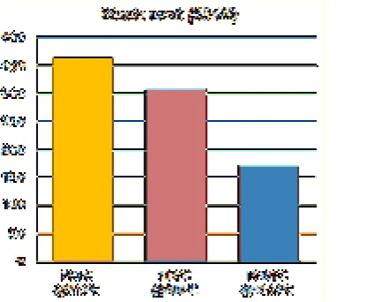
fabrication. Therefore, several earlier studies have conducted manufacturing cost analyses for several different SOFC production volumes and system sizes [33][34]. To summarize, the stack cost comprises cell cost (raw materials and production) and balance of stack cost (components surrounding each cell). Numerous studies and cost projections have been performed for automotive fuel cell systems [35] and combined heat and power applications [36]. Direct stack manufacturing costs are mainly modeled for large appliances, whose net electricity capacities range between 1-250 kWe. Overall stack manufacturing costs range from $166 kW/e to $5,387 kW/e for a 250 kWe system at 50,000 systems per year. [37]. Dubois et al. [38] performed a comparative and extensive cost study between the fabrication of protonic ceramic fuel cells (PCFC) and SOFC stacks and the study demonstrated the cell raw material cost for SOFCs is 35% lower compared to PCFCs. For the total cost stack, it is shown in Figure 6 that SOFC stack operating in methane fuel at 800oC is estimated to be 27% lower than its PCFC counterpart operating at 500oC whereas for low operating temperature fuel cell, PEMFC, the total cost stack is expected to be much lower than both PCFC and SOFC. Operating at a low temperature enables PEMFC to have a wide variety of material selection resulting in a lower material cost compared to
hydrocarbon fuels and reduce the operating temperature (less than 600oC) [40].
Fig. 6 Total cost distribution of PCFC, SOFC and PEMFC stack
5.
Conclusions
The commercialization of SOFCs for portable applications has yet to succeed given the various challenges in material selection and stack design and the high fabrication cost. Considering that micro-SOFCs can only be operated in a reduced operating temperature, advanced knowledge and technology bear importance in fabrication of thin film membranes with a large active area to produce a reasonable power output. In addition to, the material challenges, cost fabrication and stack design, the membrane microstructures for micro-SOFCs depend on parameters such as chemical composition, the deposition technique used, and substrate to ensure good stability and durability for long-term usage. Hence, fundamental issues need to be resolved before it can succeed in the market. The authors note that there remains significant uncertainty in stack cost fabrication associated materials, manufacturing processes and equipment facility. Although wide research have been conducted on fabricating micro fuel cells, with either the materials used or the process involved, extensive research is still needed for commercialization of SOFCs for portable applications.
Acknowledgement
This work was supported by Universiti Kebangsaan Malaysia (UKM) via research sponsorship of GUP-2016-045.
References
[1] Ebshish, A.,Yaakob, Z., Narayanan, B., Bshish, A., Ramli, W., and Daud, W. The Activity of Ni-Based Catalysts on Steam Reforming of Glycerol for Hydrogen Production. International Journal of Integrated Engineering, Volume 3, (2011), pp. 5–8.
[2] Mahato, N., Banerjee, A., Gupta, A., Omar, S., and Balani, K. Progress in material selection for solid oxide fuel cell technology: A review.
Progress in Materials Science, Volume 72, (2015), pp. 141–337.
[3] Blum, L., Deja, R., Peters,R., and Stolten, D. Comparison of efficiencies of low, mean and high temperature fuel cell Systems.International Journal of Hydrogen Energy, Volume 36, (2011), pp. 11056–11067.
[4] Timurkutluk, B., Timurkutluk, C., Mat, M. D., and Kaplan, Y. A review on cell/stack designs for high performance solid oxide fuel cells.
Renewable and Sustainable Energy Reviews, Volume 56, (2016), pp. 1101–1121.
[5] Baldinelli, A., Barelli, L., and Bidini, G. Performance characterization and modelling of syngas-fed SOFCs (solid oxide fuel cells) varying fuel composition. Energy, Volume 90, (2015), pp. 2070–2084.
[6] Minh, N. Q. Solid oxide fuel cell technology - Features and applications. Solid State Ionics, Volume 174, (2004), pp. 271–277.
[7] da Silva, F. S. and de Souza, T. M. Novel materials for solid oxide fuel cell technologies: A literature review.International Journal of Hydrogen Energy, Volume 42, (2017), pp. 26020–26036.
[8] Rashid, K., Dong, S. K., Khan, R. A., and Park, S. H. Optimization of manifold design for 1 kW-class flat-tubular solid oxide fuel cell stack operating on reformed natural gas. Journal of Power Sources, Volume 327, (2016), pp. 638– 652.
[9] Singhal, S. C. and Kendall, K. High-temperature solid oxide fuel cells: fundamentals, design, and applicatons, (2003).
[10] Evans, A., Bieberle-hütter, A., Rupp, J. L. M., and Gauckler, L. J. Review on microfabricated micro-solid oxide fuel cell membranes.Volume 194, (2009), pp. 119–129.
[11] Bieberle-h, A. et al. A micro-solid oxide fuel cell system as battery replacement. Journal of Power Sources, Volume 177, (2008), pp. 123–130. [12] Sandhu, N. K. et al. Electrochemical performance
of a short tubular solid oxide fuel cell stack at intermediate temperatures. Applied Energy, Volume 183, (2016), pp. 358–368.
[13] Baharuddin, N. A., Muchtar, A., and Somalu, M. R. Short review on cobalt-free cathodes for solid oxide fuel cells. International Journal of Hydrogen Energy, Volume 42, (2016), pp. 9149– 9155.
[14] Pan, K., Hussain, A. M., and Wachsman, E. D. Anode materials for low-temperature solid oxide fuel cells. Journal of Power Sources, Volume 347, (2017), pp. 277–282.
3-σ Infiltration. Journal of the Electrochemical Society, Volume 161, (2014), pp. F668–F673. [16] Choi, S., Wang, J., Cheng, Z., and Liu, M.
Surface Modification of Ni-YSZ Using Niobium Oxide for Sulfur-Tolerant Anodes in Solid Oxide Fuel Cells. Journal of The Electrochemical Society, Volume 155, (2008), pp. 449-454. [17] Raharjo, J., Muchtar, A.,Wan Daud,W. R.,
Muhamad, N., and Majlan, E. H. Pencirian Fizikal dan Terma Komposit Seramik Elektrolit SDC-(Li/Na)2CO3. Sains Malaysiana, Volume
41, (2012), pp. 95–102.
[18] Mahmud, L. S., Muchtar, A., and Somalu, M. R. Influence of sintering temperature on NiO-SDCC anode for low-temperature solid oxide fuel cells (LT-SOFCs). Ceramics - Silikaty, Volume 60, (2016), pp. 317–323.
[19] Wang, S. F., Hsu, Y. F., Chang, J. H., Cheng, S., and Lu, H. C. Characteristics of Cu and Mo-doped Ca3Co4O9-δ cathode materials for use in
solid oxide fuel cells. Ceramics International, Volume 42, (2016), pp. 11239–11247.
[20] Zhou, Q. et al. Novel cobalt-free cathode material (Nd0.9La0.1)2(Ni0.74Cu0.21Al0.05)O4+δfor
intermediate-temperature solid oxide fuel cells.
Ceramics International, Volume 41, (2014), pp. 639–643.
[21] Baharuddin, N. A., Muchtar, A., Somalu, M. R., and Samat, A. A. Thermal Decomposition of Cobalt-free SrFe0.9Ti0.1O3-δ Cathode for
Intermediate Temperature Solid Oxide Fuel Cell.
Procedia Engineering, Volume 148, (2016), pp. 72–77.
[22] Hoa, N. K., Rahman, H. A., and Somalu, M. R.
Influence of Silver Addition on the
Morphological and Thermal Characteristics of Nickel Oxide-Samarium Doped Ceria Carbonate ( NiO-SDCC ) Composite Anode. International Journal of Integrated Engineering, Volume 10, (2018), pp. 196–201.
[23] Millichamp, J. et al. A study of carbon deposition on solid oxide fuel cell anodes using electrochemical impedance spectroscopy in combination with a high temperature crystal microbalance. Journal of Power Sources, Volume 235, (2013), pp. 14–19.
[24] Singh, B., Ghosh, S., Aich, S., and Roy, B. Low temperature solid oxide electrolytes (LT-SOE): A review. Journal of Power Sources, Volume 339, (2017), pp. 103–135.
[25] Hossain, S., Abdalla, A. M., Zaini, J. H., Savaniu, C. D., Irvine,J. T. S., and Azad,A. K. Highly dense and novel proton conducting materials for SOFC electrolyte. International Journal of Hydrogen Energy, Volume 42, (2017), pp. 27308–27322.
[26] Falk-Windisch, H., Claquesin, J., Sattari, M., Svensson, J.-E., and Froitzheim, J.Co- and Ce/Co-coated ferritic stainless steel as interconnect material for Intermediate
Temperature Solid Oxide Fuel Cells. Journal of Power Sources, Volume 343, (2017), pp. 1–10. [27] Mah, J. C. W., Muchtar, A., Somalu, M. R., and
Ghazali, M. J.Metallic interconnects for solid oxide fuel cell: A review on protective coating and deposition techniques. International Journal of Hydrogen Energy, Volume 42, (2017), pp. 9219–9229.
[28] Shaigan, N., Qu,W., Ivey, D. G., and Chen,W. A review of recent progress in coatings, surface modifications and alloy developments for solid oxide fuel cell ferritic stainless steel interconnects. Journal of Power Sources, Volume 195, (2010), pp. 1529–1542.
[29] Hedayat, N., Du,Y., and Ilkhani, H. Review on fabrication techniques for porous electrodes of solid oxide fuel cells by sacrificial template methods. Renewable and Sustainable Energy Reviews, Volume 77, (2017), pp. 1221–1239. [30] Lee, S.-B., Lim, T.-H., Song, R.-H., Shin, D.-R.,
and Dong, S.-K. Development of a 700W anode-supported micro-tubular SOFC stack for APU applications. International Journal of Hydrogen Energy, Volume 33, (2008), pp. 2330–2336. [31] Mushtaq, U. et al. Effect of cathode geometry on
the electrochemical performance of flat tubular segmented-inseries (SIS) solid oxide fuel cell.
International Journal of Hydrogen Energy, Volume 40, (2015), pp. 6207–6215.
[32] Sopian, K. and Wan Daud, W. R. Challenges and future developments in proton exchange membrane fuel cells. Renewable Energy, Volume 31, (2006), pp. 719–727.
[33] Battelle. Manufacturing Cost Analysis of 1 KW and 5 KW Solid Oxide Fuel Cell (SOFC) for Auxilliary Power Applications. U.S. Department of Energy, (2014).
[34] James, B. D., Spisak, A. B., and Colella, W. G. Manufacturing Cost Analysis of Stationary Fuel Cell Systems. National Renewable Energy Laboratory, (2012).
[35] Carlson, E. J., Kopf, P., Sinha, J., Sriramulu, S., and Yang, Y. Cost Analysis of PEM Fuel Cell Systems for Transportation. National Renewable Energy Laboratory, (2005)
[36] Weimar, M. R., Chick, L. A., Gotthold, D. W., and Whyatt, G. A. Cost Study for Manufacturing of Solid Oxide Fuel Cell Power Systems. U.S. Department of Energy, (2013), p. 50.
[37] Scataglini, R., Wei, M., Mayyas, A., Chan, S. H., Lipman, T., and Santarelli, M.A. Direct Manufacturing Cost Model for Solid-Oxide Fuel Cell Stacks. Fuel Cells, Volume 17, (2017), pp. 825–842.
[39] Wee, J. H. Applications of proton exchange membrane fuel cell systems. Renewable and Sustainable Energy Reviews, Volume 11, (2007), pp. 1720–1738.
[40] Cimenti, M. and Hill, J. M. Direct utilization of liquid fuels in SOFC for portable applications: Challenges for the selection of alternative anodes.
Energies, Volume 2, (2009), pp. 377–410. [41] Stambouli, A. B. and Traversa, E. Solid oxide
fuel cells (SOFCs): A review of an
environmentally clean and efficient source of energy. Renewable and Sustainable Energy Reviews, Volume 6, (2002), pp. 433–455.