ISSN (e): 2250-3021, ISSN (p): 2278-8719
Vol. 08, Issue 6 (June. 2018), ||V (VI) || PP 15-22
Insulation of a material: Effects on temperature gradient and
temperature difference
Taiwo O. Oni, Samson I. Odunola, Joseph Odolomerun, Stanley C. Obisirike
Department of Mechanical Engineering, Faculty of Engineering Ekiti State University, P. M. B. 5363, Ado-Ekiti, Nigeria
Corresponding author: Taiwo O. Oni
Abstract:
-
The effects of insulation on temperature gradient and temperature difference in a material were inquired in this study. Four 0.25m-diameter plain cylindrical rods with different thickness of insulation between 10mm and 40mm and one 0.25m-diameter plain cylindrical rod were considered. The heat transfer rate was varied between 660W and 3300W. The plain rod has a highest temperature of 448K at x = 0, but the rod with 40mm insulation thickness has the lowest temperature of 340K at x = 0.35m. A highest temperature difference of 65K was obtained with the rod with 40mm insulation thickness at x = 0.35m.and the highest temperature gradient of 544.45Km-1 was obtained with the rod with 40mm insulation thickness at x = 0.07m. A maximum value of 207.35 Km-1 of temperature gradient was obtained in the rod of 40mm insulation thickness at 3300W, whereas a minimum value of 105.71Km-1 of temperature gradient was obtained in the plain rod at 660W.Keywords: -
Temperature gradient, thickness, temperature, heat transfer rate, insulation--- --- Date of Submission: 07-06-2018 Date of acceptance: 26-06-2018 --- ---
I.
INTRODUCTION
The degree of hotness or coldness of a body or a system is generally referred to as temperature. Heat energy is transferred from one part of a body or a system to another part as a result of temperature difference between the two parts. Temperature difference per unit distance through which the heat is transferred is known as temperature gradient [1, 2]. Heat energy has found applications in areas such as heat pipes, aerospace, automobiles, solar water heaters, electronics systems, medicines, and refrigeration plants [3]. In all these applications, both temperature and temperature gradient are determinants of the heat energy. The effects of insulations on temperature difference and temperature gradient in a material at various heat transfer rate were determined experimentally in this research.
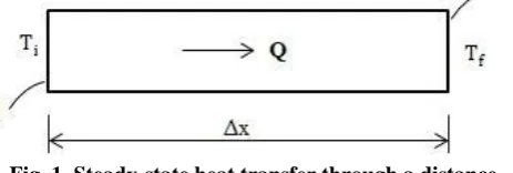
Consider a steady-state heat transfer through a distance Δx = L in a material, as shown in Fig. 1. The
Fig. 1. Steady-state heat transfer through a distance
temperature difference at a point (x) across the material is ∆T =Tx - Ti, where Ti (K) and Tx (K) are the initial
temperature and temperature at point x, respectively, of the material. In the submission of Fourier, as presented by Cengel [4] and Incropera et al. [1], the rate of the heat transfer through the material is directly proportional to the temperature difference (∆T) across the material and the heat transfer area (A) normal to the direction of heat transfer, but is inversely proportional to the distance (∆x) through which the heat is transferred. Mathematically, this statement can be expressed as:
(1)
where the constant (W/m.K) is known as the thermal conductivity of the material, which is a measure of the ability of the material to conduct heat.
II.
PROCEDURE OF THE EXPERIMENTS
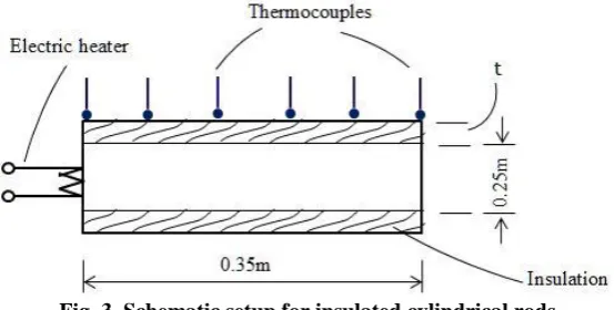
In carrying out the investigation, five different samples were used. The first sample was a plain (that is, uninsulated) cylindrical rod of diameter d = 0.25m and length L = 0.35m, as shown in Fig. 2. The plain cylindrical sample is made of steel of thermal conductivity 15.1 W/m.K [4]. The other four samples, depicted in Fig. 3, were insulated cylindrical rod of length 0.35m. The four insulated cylindrical rods were plain cylindrical rods covered individually with cement mortal insulator of thermal conductivity 0.72 W/m.K [1] and various thickness (t) with . The 0.25m uninsulated cylindrical rod serves as the inner diameter (d) for the insulated cylindrical rods of thickness, t, as presented in Fig. 3. The outer diameter (do) for the insulated
rods was determined by Eq. (2) and presented in Table 1.
(2)
Table 1. Outer diameter ( ) of insulated cylindrical rods
Insulation thickness, t (m) 0.01 0.02 0.03 0.04 Outer diameter, do (m) of insulated rods 0.045 0.065 0.085 0.105
An electric heater, which was connected to electrical mains, was attached to each of the end, at x = 0, of the plain and insulated samples, as shown schematically in Fig. 2 and Fig. 3. The voltage of the electric heater was 220V and its current was varied between 3 and 15A, thus providing different values of electrical power consumed by the heater and converted to heat generated in the heater as a result of resistance heating. Table 2 shows the different values of the electrical power.
Fig. 2. Schematic setup for plain cylindrical rod
Fig. 3. Schematic setup for insulated cylindrical rods
Table 2. Different values of electrical power
Current, I (A) 3 5 7 11 13 15 Heat transfer rate, Q (W) 660 1100 1540 2420 2860 3300
thermocouples were placed at six different positions (x = 0, 0.07, 0.14, 0.21, 0.28, and 0.35m) on the surface of each of the plain and insulated rods to measure the surface temperature under steady operating conditions.
In Table 3 were recorded the calculated temperature (Tx) along each of the rods, which have been read
by the thermocouples, for heat transfer rate of 660W. For each of the rods, the temperature difference (∆Tx = Tx
- Ti) between a point x along the rod and the beginning of the rod (i.e. at x = 0), as well as the temperature
gradient (ΔT/x) for heat transfer rate of 660W were calculated and recorded in Table 4 and Table 5, respectively. In Table 6, Table 7, Table 8, and Table 9 were recorded the calculated temperature at the beginning of each of the rods (Ti), the temperature at the end of each of the rods (Tf), the temperature difference
at the end of each of the rods (Ti - Tf), and the temperature gradient at the end of each of the rods ((Ti - Tf ) / L),
respectively, against the changes in the heat transfer rate.
Table 3. Temperature along the cylindrical rods at Q = 660W for various insulation
Tx (K)
x (m) Plain rod
10mm ins. rod 20mm ins. rod 30mm ins. rod 40mm ins. rod
0 448 441 428 416 405
0.07 430 419 401 382 367 0.14 424 415 396 376 360 0.21 421 409 388 367 350
0.28 417 407 387 366 349
0.35 411 402 380 358 340
Table 4. Temperature difference along the cylindrical rods at Q = 660W for various insulation
ΔT (K)
x (m) Plain rod
10mm ins. rod 20mm ins. rod 30mm ins. rod 40mm ins. rod
0 0 0 0 0 0
0.07 18 22 27 34 38
0.14 24 26 32 40 45
0.21 27 32 40 49 55
0.28 31 34 41 50 56
0.35 37 39 48 58 65
Table 5. Temperature gradient along the cylindrical rods at Q = 660W for various insulation
ΔT/x (K/m)
x (m) Plain rod
10mm ins. rod 20mm ins. rod 30mm ins. rod 40mm ins. rod
0 0 0 0 0 0
0.07 257.14 314.86 392.11 481.97 544.45 0.14 171.43 186.43 230.86 282.74 318.16 0.21 128.57 154.67 190.36 232.24 260.23 0.28 110.71 120.14 147.74 180.15 201.73
Table 6. Inlet temperature against heat transfer rate along the cylindrical rod for various insulation
Ti (K)
I (A) Q (W) Plain rod
10mm ins. rod 20mm ins. rod 30mm ins. rod 40mm ins. rod 3 660 448 441 428 416 405 5 1100 459 452 439 426 415 7 1540 466 458 445 433 421
11 2420 478 470 457 444 432
13 2860 484 477 463 450 438
15 3300 493 486 472 458 446
Table 7. Outlet temperature against heat transfer rate along the cylindrical rod for various insulation
To (K)
I (A) Q (W)
Plain rod 10mm ins. rod 20mm ins. rod 30mm ins. rod 40mm ins. rod 3 660 411 402 380 358 340 5 1100 421 412 390 367 349 7 1540 427 418 396 372 354
11 2420 439 429 406 383 364
13 2860 445 435 412 388 369
15 3300 453 443 419 395 376
Table 8. Temperature difference against heat transfer rate along the cylindrical rod for various insulation
ΔT (K)
I (A) Q (W)
Plain rod 10mm ins. rod 20mm ins. rod 30mm ins. rod 40mm ins. rod
3 660 37 39 48 58 65
5 1100 40 42 51 61 68
7 1540 40 42 51 62 69
11 2420 44 46 55 66 74
13 2860 45 47 56 67 75
15 3300 45 48 57 68 76
Table 9. Temperature gradient against heat transfer rate along the cylindrical rod for various insulation
ΔT/x (K/m)
I (A) Q (W) Plain rod
11 2420 116.53 122.56 149.08 180.31 200.86
13 2860 118.11 124.23 151.13 182.80 203.64
15 3300 120.23 126.46 153.86 186.13 207.35
III.
DISCUSSION OF RESULTS OF THE FINDINGS
This section discusses the results of the findings from investigations conducted in this research. Fig. 4 shows that the temperature along each of the rods decreased from inlet towards their upstream, and that the rod with largest insulation thickness had the least temperature. For the case considered, the plain rod has the highest temperature of 448K at x = 0, but the rod with 40mm insulation thickness has the least temperature of 340K at x = 0.35m. A highest temperature difference of 65K was obtained with the rod with 40mm insulation thickness at x = 0.35m (Fig. 5) and, as shown in Fig.6, a highest temperature gradient of 544.45Km-1 was obtained with the rod with 40mm insulation thickness at x = 0.07m.
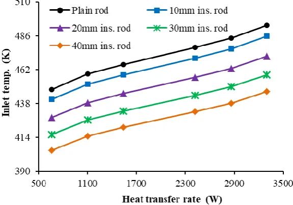
As can be seen in Fig. 7, the temperature at the beginning of the rods increased with the increase of heat transfer rate, but decreased with the increase of insulation thickness. The results for temperature at the end of the rods follow this same pattern of results as evidenced in Fig. 8. A minimum temperature of 405K at the beginning of the rods was obtained at 660W in the rod with 40mm insulation thickness but a maximum of 493K was obtained at 330W in the uninsulated sample.
Fig. 4. Temperature along the cylindrical rods at Q = 660W for various insulation
Fig. 6. Temperature gradient along the cylindrical rods at Q = 660W for various insulation
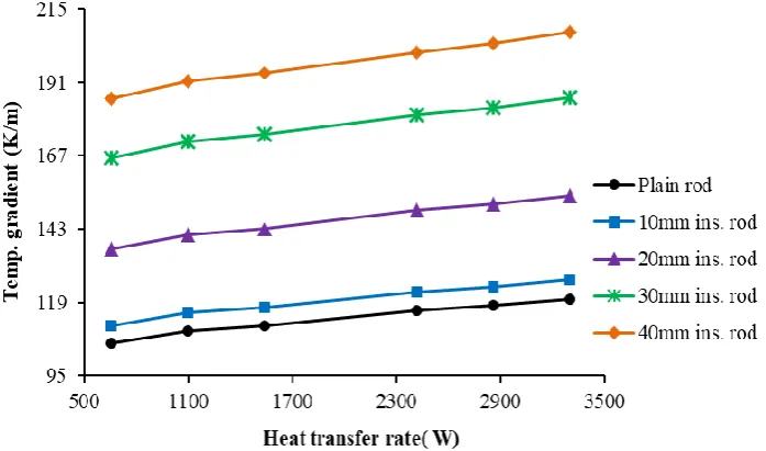
The temperature difference and temperature gradient at the end of the rods for various insulation thicknesses and various heat transfer rate follow the same pattern of results, as evident in Figs 9 and 10. At the end of the rod, a minimum temperature difference of 37K was obtained in the plain rod at 660W while a maximum of 76K was obtained in the rod of 40mm insulation thickness at 3300W. For the temperature gradient (Fig. 9), a maximum of 207.35 Km-1 was obtained in the rod of 40mm insulation thickness at 3300W, but in the uninsulated rod at 660W, a minimum temperature gradient of 105.71Km-1 was obtained.
Fig. 8. Outlet temperature against heat transfer rate along the cylindrical rod for various insulation
Fig. 9. Temperature difference against heat transfer rate along the cylindrical rod for various insulation
IV.
CONCLUSION
Experiments were carried out to probe the effects of insulation on temperature gradient and temperature difference in a material. It was discovered, through this study, that a material with highest insulation thickness has the least temperature and that increasing the heat transfer rate will result in an increase of the temperature difference and temperature gradient of the material. Thus, the study has revealed how insulation and heat transfer rate impact the temperature gradient, temperature, and temperature difference of a material.
REFERENCES
[1]. F. P. Incropera, D. P. Dewitt, T. L. Bergman, and A. S. Lavine, Fundermentals of heat and mass transfer
(USA: John Wiley and sons, 2007).
[2]. T. O. Oni, Determination of maximum number of layers of solar collector for fish solar dryer, J. Eng. Applied Sci., 3(7), (2008), 553-559.
[3]. T. O. Oni and M. C. Paul, CFD investigation of the impacts of variation in geometry of twisted tape on heat transfer and flow characteristics of water in tubes, Heat Transf. Asian Res., 45(5), (2016), 482-498. [http://dx.doi.org/10.1002/htj.21216].
[4]. Y. A. Cengel, Heat transfer - A practical approach (New York: McGraw-Hill Co. Inc., 2003).