Automatic Wheelchair with Essential Applications
Divya R Akhila Aniyan
Department of Electronics & Communication Engineering Department of Electronics & Communication Engineering Mount Zion College of Engineering and Technology,
Pathanamthitta, Kerala, India
Mount Zion College of Engineering and Technology, Pathanamthitta, Kerala, India
Feba Jose Abhilash R
Department of Electronics & Communication Engineering Department of Electronics & Communication Engineering
MACFAST Thiruvalla STCET Chengannur
Abstract
This work presents the development of a robotic wheelchair that can be commanded by users. It provides flexibility to choose different modalities to command the wheelchair, in addition to be suitable for people with different levels of disabilities like partially paralyzed, by birth disabilities, accidental injuries etc. Users can command and control the wheelchair based on their head movements. Also, the user can control some home appliances. As a trial, we work on the lighting system in a room that is ON and OFF mechanism of a light. The wheelchair can also operate like an auto-guided vehicle, with the help of obstacle sensors, which detects the obstacles in front of it, and it either stops or takes deviation. A main door detection section is provided with a magnetic sensor in the wheelchair and a magnet fixed at the main door for safety and then the wheelchair stops. A security as well as a safety alarm is provided in the device, which beeps when the device may hit somewhere or an emergency situation occurs. Head movements are used for both moving the device and for controlling directions of the device. This device is capable of lighting the room by eye movements.
Keywords: Eye blink sensor, HT12E/D, magnetic sensor, obstacle sensor, PIC micro controllers, tilt switch
________________________________________________________________________________________________________
I.
INTRODUCTION
Robotic technologies have the potential to improve the lifestyles of people suffering from one or more disabilities. Related developments are often grouped under the terms Rehabilitation Technologies or Assistive Technologies. They attempt to restore human abilities that have been reduced or lost by disease, accident, or old age. Mobility is one such function. Robotic wheelchairs extend the capabilities of traditional powered devices by introducing control and navigational intelligence. These devices can ease the lives of many disabled people, particularly those with severe impairments, by increasing their range of mobility. Without wheelchairs, many disabled people can become prisoners in their own homes, unable to access education or employment. That is why the estimated 25 million people in the world who need a wheelchair, but do not have one, are often among the most disadvantaged and poor in society. A suitable wheelchair can be a vital means of mobility, enabling participation in family and community activities, from income generation to advocacy of human rights. There are many reasons why a person may not be able to travel freely, including motor control problems, spinal injuries, and amputation[3]. A wheelchair is a mechanical device that can often assist. Now the researches are aimed at creating ‘intelligent’ devices that can sense information from their environment and respond in useful ways. The designing robotic wheelchair use head tilt movement to steer the wheelchair. In addition, we can give more independence to the disabled person by using the eye blink to communicate with the devices in a room like operating a light or a fan. This communication is done using a RF transmitter and receiver[2]. The overall framework of this work is to restore autonomy to severely disabled people by helping them use independently a power wheelchair. The amount of work that the rider chooses to do and how much control is taken by the chair is decided by the rider and his or her care.
II.
LITERATURE SURVEY
Many groups have proposed or developed robotic wheelchairs. Most robotic wheelchairs are implemented by modifying existing Powered Wheelchair systems. One such project, the Tin Man wheelchair, uses servomotors to control the host chair through an unmodified joystick. Wheelchair equipment has also been designed from scratch. These devices enhance traditional designs in order to increase the possibilities of travel in challenging environments. Some of the earliest work in the development of intelligent wheelchairs was a system implemented by Connell and Viola in which a chair is mounted on top of a robot to make it mobile. Mr. Ed, as the chair was called, could be controlled by the user using a
movements of the user. The user can operate the electrical appliances in the room with eyes. This is a very safe and secure device with an obstacle sensor, main door detection system and an alarm system. This device is also very simple to implement with a tilt switch, eye blink sensor and other components with in associated with two PIC microcontrollers. The research methodology is developed under the following assumptions:
1) To use wheelchair automatically for moving forward, backward, Left & Right through head movements. 2) Our project Automatic wheelchair basically works on the principle of tilt switch and sensors.
3) When person tilt his head in forward direction above 20 degree angle chair will move in forward direction. 4) If person tilt his head in backward direction above 20 degree angle chair will move in backward direction. 5) If person tilt his head in left direction above 20 degree angle chair will move in left direction.
6) If person tilt his head in right direction above 20 degree angle chair will move in right direction.
7) An eye blink sensor attached to a spectacle helps to operate the home appliances such as light and fan by the user. 8) An obstacle sensor, magnetic sensor and an alarm system is providing to achieve maximum safety.
III.
DESIGN AND IMPLEMENTATIONS
To design the system and to implement it, a circuit has to be followed, for that it requires a number of hardware components including microcontrollers. These components are assembled on a PCB board. Software is very important to make a microcontroller working. For this project two microcontrollers are used. The prototype chair is implemented with a small chair, here we use a simple demonstration vehicle with two wheels and considering that the real wheelchair will works same as that of the demonstration. We use 60rpm or a 45rpm motors as our speed requirement to move the chair. 12V rechargeable battery is used to run the motors. A microcontroller is an ‘all in one' processor, the processor, RAM, ROM, IO all on the one chip. Microcontroller is specific purpose device. PIC16F877A - is the microcontroller being used to operate the wheelchair. PIC16F676 is the microcontroller used to manage the operation of home devices according to the commands from master unit.
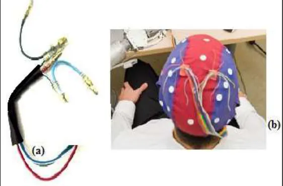
Fig. 2: Placing of an eye blink sensor on a spectacle.
Microcontroller is used to control the device. The rest of the modules are controlled by the microcontroller. The wheelchair can be operated in two modes wheelchair control mode and home appliance control mode. The tilt switches are programmed to control the movement of the wheelchair in wheelchair control and eye blink sensor is programmed to control home appliances in home appliance control mode. In addition, we are tried to give more independence to the handicapped people
by using the eye blink sensor to control home appliances. This communication is done using a RF Transmitter/Receiver[2]. Using this disabled person can control various devices easily. RF module comprises of a transmitter and a receiver. It operates at a frequency of 434MHz. RF transmitter receives serial data and transmits it wirelessly through RF through its antenna. The transmission occurs at the rate of 1Kbps - 10Kbps. The RF module is often used along with a pair of encoder/decoder. The encoder is used for encoding parallel data for transmission feed while reception is decoded by a decoder. The obstacle sensor is placed at the bottom of the wheelchair. It is used to stop the wheelchair in case there is an obstacle. The obstacle sensor stops the wheelchair completely and it must be reset to operate again. Mercury tilt switch is used for the direction selection. Four switches are aligned parallel to horizontal surface and bind it, this is attached either to a cap or to a headphone and can fix on the user’s head. To control the home appliances like light and fan an eye blink sensor attached to a spectacle is used. As wide varieties of wheelchairs are available we tried to develop one with easy implementation, user friendly and affordable for everyone. Four control commands were implemented, namely ‘going forward’, ‘turning right’, ‘turning left’ and ‘reversing ’[1]. In both control modes, the user does not have to maintain the head movement during the control command. Experimental results show that the proposed HMI is reliable for controlling a wheelchair.
Wheelchair Controlling A.
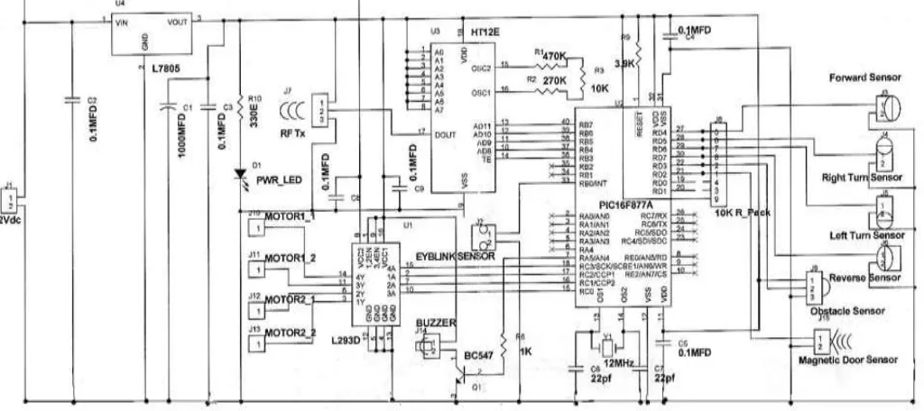
Fig. 3. shows a simplified block diagram for the working and controlling of wheelchair with head movements and other features of the system. PIC16F877A microcontroller unit is used to control the entire working. Head movements are analyzed with the movements of tilt switches attached on the head using a head phone or a cap as shown in fig.1 and thus the programmed microcontroller runs and send commands to the motor drivers and then wheelchair moves that direction. Power supply, a 12V DC power supply is used to turn the vehicle ON. Instead of 12V DC, a 230V, 50Hz AC can be used with an adapter of 1A, 12V SMPS. A voltage regulator of 12V to 5V is used, as 5V is sufficient for all components except the motors. For driving the motors 12V is required. An LED is given to indicate the power. This is to detect whether the connection is perfect and supply is there, which indicates the circuit is power ON. Wireless transmitters, an RF transmitter of 433MHz of either ASK or FSK is used to send commands. An encoder is used associated with transmitter. A magnetic sensor is provided for main door detection to avoid the unexpected accidents for the user. A strong magnet is placed at the floor of the main door, when the wheelchair reaches the main door the magnetic sensor attached in wheelchair sense the magnet then it automatically stops and security alarm beeps. An obstacle sensor is provided to detect the obstacle and device stops with beeping alarm. This device is designed very precisely with more security and safety systems and very comfort and easy for using.
Fig. 3: Block diagram for controlling wheelchair.
HT12E’s 17th pin. Pins 1 to 8 of HT12E are the address pins. Here theses are kept high. For the oscillator circuit a 750K resistance is constructed by connecting 270K, 470K and 10K in series. Pin 33 of microcontroller i.e. RB0 of PORTB is connected to an eye blink sensor. Lower nibble- RC0 to RC3 - of PORTC is used to control motors. A driver IC L293 is used to amplify the current and voltage of control signals from MC. Pins 2, 7, 10 and 15 are the input pins of L293. Pins 3, 6, 11 and 14 are its corresponding outputs. Pins 1 and 9 enables the circuit sections by connecting to VCC and pins 4,5,12 and 13 are the grounded. Pin 8 is connected to 12V supply and pin 16 is connected to 5V supply. PORTD receives the signals from head movement sensors, obstacle sensor and door sensor. This port is pulled up with a 10K resistor pack. Door sensor is connected to RD2, obstacle sensor[1] is connected to RD3 and direction sensors using head movement are connected to the higher nibble.
Home Appliance Controlling B.
Home appliances are controlled by using the eye blinks with the help of an eye blink sensor, which senses the blink and then it is transmitted to the receiver. The RF receiver receives the command and runs the microcontroller, for home appliance controlling a PIC16F676, microcontroller is needed. The decoder decodes the encoded signal which is transmitted by the RF transmitter received by RF receiver[2]. A power supply is required for operating overall device. The eye blink sensor[1] is attached on a spectacle as shown in fig.2. When an obstacle and an eye blink with a specified delay occurs then the light turns ON. When an eye blink with a specific delay occurs the fan turns ON. The block diagram is illustrated in fig.6.
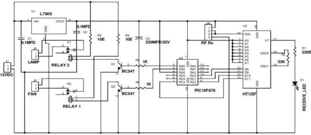
As illustrated in fig.5, it is the designed circuit diagram for controlling the home appliances. A simple PIC16F676 is the microcontroller used to manage the operation of home devices
Fig. 5: Circuit diagram used for controlling the home appliances.
Fig. 6: Block diagram for home appliance controlling.
according to the commands from master unit. MC receives the commands through the decoder IC HT12D and RF receiver connected to the pin 14 of the decoder. Pins 10 to 13 of the decoder are connected to the pins 7 to 10 of MC. Pins 1 to 8 of decoder are connected to VCC to make the address high. A 33K resistor is connected on pins 15 and 16 to complete the circuit of oscillator. Pins 2 and 3 of MC drive the electric equipments through the relay and the driver transistors. BC547 transistor amplifies the voltage and the current of the signal from MC and drives the relay. Relay provides isolation between the circuits using AC 230V power and DC12V power. A regulator IC L7805 is used to regulate the 12V to 5V. The capacitors associated with the regulator filters noises.
IV.
ADVANTAGES AND APPLICATIONS
New implementations can be introduced into this such as implementation of live monitoring system and a smart phone alert for providing safety. Another measure to adopt safety is implementation of the device traveling through a pre-determined path.
ACKNOWLEDGMENT
We would like to thank everyone who supported us to do this study especially to Ass. Prof. Bejoy Antony, STCET who guided us and Mr. Ninan John who assisted us throughout this work.
REFERENCES
[1] Teodiano Freire Bastos-Filho, Fernando Auat Cheein, SandraMara Torres Müller, Wanderley Cardoso Celeste, Celso de la Cruz, Daniel Cruz Cavalieri, Mário Sarcinelli-Filho, Paulo Faria Santos Amaral, Elisa Perez, Carlos Miguel Soria, and Ricardo Carelli, “Towards a New Modality-Independent Interface for a Robotic Wheelchair”, IEEE transactions on neural systems and rehabilitation engineering, Volume 22,No.3, May 2014.
[2] Colleen Nelson, Nikitha S Badas, Saritha I G, Thejaswini S, Colleen Nelson et al, “Robotic Wheelchair Using Eye Blink Sensors and Accelerometer Provided with Home Appliance Control”, Int. Journal of Engineering Research and Applications, Vol. 4, Issue 5, May 2014.
[3] Gunda Gautam, Gunda Sumanth, Karthikeyan K C, Shyam Sundar, D.Venkataraman, “Eye Movement Based Electronic Wheel Chair For Physically Challenged Persons” International Journal of Science and Technology Research volume 3, issue 2, February 2014.
[4] Prof. R.S.Nipanikar, Vinay Gaikwad, Chetan Choudhari, Ram Gosavi, Vishal Harne, “Automatic wheelchair for physically disabled persons”, International Journal of Advanced Research in Electronics and Communication Engineering (IJARECE) Volume 2, Issue 4, April 2013.