ISSN (e): 2250-3021, ISSN (p): 2278-8719
Vol. 09, Issue 5 (May. 2019), ||S (V) || PP 21-30
An Implementation of Novel Fault Current Limiter Bridge Type
Solid State Fault Current Limiter Baed on Ac/Dc Reactor
Kishor G Mhaske
1, Praful S. Tadse
2, Prof. Prof. S.L. Shaikh
3,
Prof. N. M Chamat
41(Department of Electrical Engineering, Walchand college of Engineering, Sangli, India)
2(Department of Electrical Engineering, BIT, BALLARPUR, India)
3(Department of Electrical Engineering, Walchand college of Engineering, Sangli, India)
4(Department of Electrical Engineering, BIT, BALLARPUR, India)
Abstract:
This paper presents the implementation of novel bridge type solid-state fault current limiter with use of single series reactor acts as AC and DC reactor. The proposed scheme uses uncontrolled and semi-controlled power electronics switches bridge rectifier with the reactor. The reactor used works as dc in normal condition and ac in a fault condition. The advantages of this proposed scheme over other fault current limiter are reactor inserts negligible impedance during normal operation and insert high impedance during fault operation and other one is simple switching. When there no fault or in the pre-fault condition it operates in dc mode and in fault condition it operates in ac mode. The switching decreases transient recovery voltage and inserts large impedance during fault period. MATLAB/Simulink software is used for simulation of the proposed BSSFCL.Keywords:
Bidirectional dc/dc converter (BDC), dual battery storage (ES1 & ES2), Fuel Cell Hybrid Electric Vehicle (FCV/HEV).I.
Introduction
another dc reactor FCL which is on the secondary side of the transformer is explained in[15]. This FCL has two coils one is reactor and another is resistor called as damping resistor connected in series .both of this is connected in shunt with IGBT like those bypass switches suppress the transients inrush current by affecting the reactor impedance. If real-time current value increased beyond the set value the damping resistor comes into picture and limits fault current by switching off of IGBT. But disadvantages of this FCL are conduction losses, switching overvoltage, complex control strategy, and cooling system also required .It can withstand with high current with limited time also due to saturation of core it loose its fault limiting capability. FCL having ac reactor may consist of mechanical or power electronic switches[16].some of the type of FCL use LC tank circuit in their structure[17]. During normal operation as a capacitor and the inductor are in resonance condition the impedance offered is negligible or small but when a fault occurs the capacitor in a series pass by switches. This will detune the LC tank circuit and impedance is inserted in the path of fault current. As those FCL have a good capability of limiting the fault current but on other hands in normal condition, it has high power loss and unacceptable over switching voltage. Arrestor in parallel can be used as a solution for the switching overvoltage. The equivalent resistance of the LC tank circuit is considerable as it produces losses which are unavoidable. The solid-state CBs are described in [18],[19].Advantages of those CBs over mechanical CBs that they are faster than mechanical CBs. As we consider the dc reactor the work well during normal operation as when a fault occurs they not successful to limit the fault current while on the other hand considering ac reactor during normal operation there is huge power loss but when it comes to limit the fault current in successfully limit the fault current .also when switching from one mode to another mode switching losses occurs. If we combine those FCL then advantages of both we can get FCL with superior advantages.
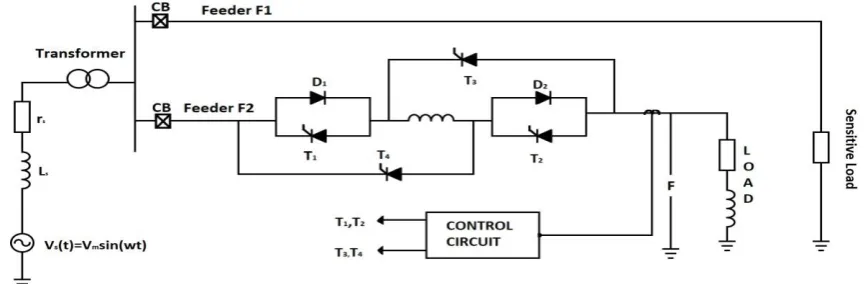
A simple bridge type solid-state fault current limiter based on ac/dc reactor is described in this paper and all the drawbacks are overcome by this BSSFCL. This proposed BSSFCL acts as a reactor during normal operation but during fault operation, it acts as an ac reactor. The reactance during normal operation is dc and in the faulted condition it is ac. This reactor can withstand with fault current for a long time also it has fast response, quick recovery after fault is removal. The power electronic switches have lower current flowing through it and also has lower voltage stress.
Fig. 1. Proposed BSSFCL configuration in two-feeders netwo
II.
Proposed BSSFCL Configuration
(a)
(b)
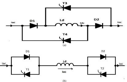
Fig. 2. BSSFCL operation modes: (a) normal operation mode (dc operationmode) and (b) fault current-limiting mode (ac operation mode).
The BSSFCL proposed has six semi-controlled and controlled switches despite older-bridge type FCL. The BSSFCL working is divided into two modes. Those normal condition and fault condition mode. When there no fault condition the proposed BSSFCL acts as dc reactor type FCL in which T3 and T4 are in ON state along with two uncontrolled switches which are diode D1 and D2 as shown in fig.
As there is a rectifier bridge arrangement it feeds dc voltage to the reactor with dc current. For the first half of cycle D1 and D2 conduct and for the next half of cycle T1 and T2 conduct. As there is dc supply is to the reactor (a rectifier converts ac into ac) the reactor acts as a short circuit in steady state condition .as reactor is short- circuited the BSSFCL is invisible from the circuit so it does cause any change in power quality. When the fault occurs the in BSSFCL configuration the switches T1and T2 are turned on and switches T3 and T4 are turned OFF while diode D1 and D2 are remains ON condition. With this D1 comes in parallel with T1 and D2 come in parallel with T2.ac current flow through reactor .the impedance of reactor limits fault current. This shows in fig 2(b).
III.
Analytical Approach of the BSSFCL
This section explains to an analytical approach to BSSFCL. The normal operation mode which is called as dc mode and the faulted mode which is ac mode is studied analytically which are shown in fig
Normal mode dc mode
As in this mode BSSFCL act bridge rectifier and provide dc voltage to the reactor as it acts dc reactor. When the fault occurs the current starts increasing. When this current crosses threshold current value then controller senses this and generates a signal to change the topology to ac mode. To calculate the current value in both modes two states are considered
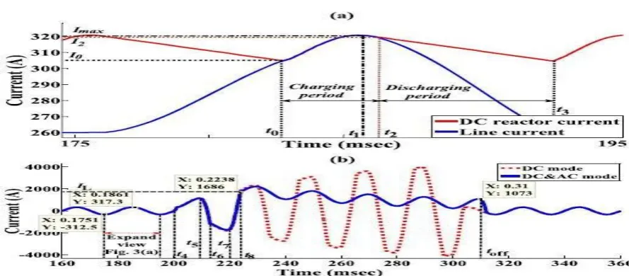
Fig. 3. (a) Expanded view of line and reactor current and (b) line current during normal and fault operation mode while operation of the BSSFCL in dc mode is shown with a dotted curve and operation of BSSFCL is in
dc mode (normal operation mode) and ac mode (fault operation mode) is shown with a solid curve
It has been shown that the dc reactor current increases gradually after fault inception and the first peak of the fault current decreases as shown with the dotted curve in Fig. 3(b). After fault occurrence, there are two charging and discharging intervals as follows:
Interval 1; Charging mode (between t4 and t5 and between t6 and t7) is shown with the dotted curve in the fig. 3(a) line current can be obtained by solving eqn no.5
(5 )
where (6)
,, , , and
Also, Ld ,rd ,Lfand VDF are dc reactor inductance and resistance ,fault inductance and resistance, and voltage drop across the power-electronic switches, respectively.
Interval 2; Discharging mode (between t5 and t6 and between t7 and t8) in this case the dc reactor current is more than the line current and hence its current freewheels through the rectifier bridge and we have
(7)
where
,
Using (7) the following equation can be obtained for the line current in the discharging mode:
Where
And the value of and have been given in the previous case after t6, another charging mode and discharging mode still exist .
AC Operation Modes:
As fault current increases and reaches IL BSSFCL topology is changed by the controller from dc mode to ac mode and we get third state as follows
is changed from dc mode to ac mode by the controller. In this case the two antiparallel switches (D1 with T1 and D2 with T2) are form that feeds the reactor with ac voltage as shown in fig 2(b) Similarly at first zero crossing of current T3 and T4 are turning off and ac voltage is induced on Ld. Impedance of the ac reactor increases with this switching pattern and the fault current amplitude decreases to specified level as shown in the fig3 (b) with solid curve we have equation
Power loss calculation:
In normal operation mode of BSSFCL, the losses are rectifier bridge and dc reactor losses. The rectifier bridge diodes are ON in a half cycle and bypass the series reactor by freewheeling action. In normal operation mode of the BSSFCL power losses are calculated are as follows
Where P Loss BSSFCL is the BSSFCL total power loss VDF is the voltage drop on each side P Loss, RB is the rectifier bridge power loss Rd is equivalent resistance of dc reactor Idc is dc side current The power losses of the BSSFCL mostly includes losses of the reactor. Therefore for practical applications it can be ignored
IV.
Design Consideration of the BSSFCL
This section places emphasis on the BSSFCL components and their design requirements for MV level, Among BSSFCL components, accessibility of the power electronic switches and series reactor in such a rating is main challenge that should be investigated.
Power Electronic Switches
High rating power electronic switches are commercially available. In addition, available power electronic switches have rather high blockage voltage and current ratings and are relatively easy to use in parallel. Use of snubber circuit is mandatory for medium voltage(MV) while it is not necessary for low voltage level(LV). The suggested BSSFCL can employ the self-turn-off switch for switching implementation in just short time. This makes the suggested BSSFCL cost effective and reliable for distribution network applications. Proper balancing between switches modules and press-packs must be kept for applications in high power applications. Also, power losses and voltage drop on switches during the fault must be taken into account. IGBT is suitable power electronic switch to use in low power applications, and available voltage levels upto 6.5 kV exist in press-packs. In addition IGCT are also available in voltage level between 2.5 kV and 10 kV and current upto 9kA. The IGCT on state power losses are low so they can be use in high power applications.
Series Reactor Design
The reactor is the main component of BSSFCL as it limits the short circuit current. In order to design series reactor into present power system, cost are decisive factor. The series reactor should be invisible during normal operation so that the influenced on the grid is minimized. Fault current can be decreased to small value by using inductance with large value but large inductor has considerable power loss. In addition, a large inductor is much more complicated to build and it increase the total time constant. For analyzing the system behavior during steady state condition and studying the effect of reactor on the fault current, the equivalent circuit of the system shown in fig. is used In this model, the source and fault impedances are ignored because their value in comparison with the reactor inductance are very small and can be neglected. The value of the electrical source is modeled by its mean value on the dc side for obtaining the dc reactor current. To obtain the dc reactor current, it is necessary to design the value of dc reactor inductance. The differential equation of the equivalent circuit is shown in fig is given in (3). By solving (3), dc reactor is obtained as given in (4),because its value in comparison with Ld is very small. In addition, we have
after fault clearance and increase the system operation delay. By considering t8 as the necessary time for changing the BSSFCL switching topology after fault inception and its corresponding current.
(12)
In [12], iL is determined via controller alignment and its capability to change the BSSFCL topology from the dc mode from ac mode. On the other hand, the value of iL is determined according to the maximum current values of the distribution network equipment. In addition, the time between t8 and t4 (t8-t4) is the BSSFCL time performance before the current of the power electronic diodes exceeds iL. furthermore, by determining the rectifier bridge output voltage (VDS), t4 and t8, it is possible to design the reactor inductance and resistance.
V.
Control Strategy
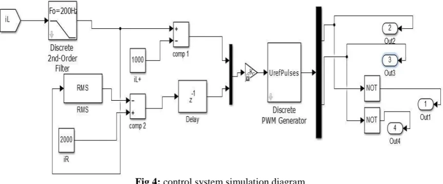
The control block diagram of the BSSFCL is shown in fig 5. In order to properly control the BSSFCL, line current ( I line ) is sampled via a transformer (CT) and sent to the control circuit. Before comparing iLine with the maximum permissible current level, it is passed from a 50-Hz band pass filter and its value is applied to comparator. Monitoring the instantaneous value of the line current increases the controller response speed in limiting the fault current at the instant of fault inception .
Fig 4: control system simulation diagram
VI.
Simulation Result
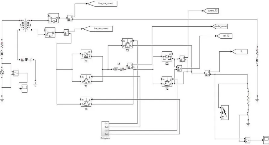
Simulation is done on MATLAB / Simulink software. Single line to ground fault (SLG) is considered for obtaining the result
Fig 5. MATLAB simulation of the proposed scheme
The network containing PROPOSED BSSFCL simulated in this section. The fig6 shows the line current when there is no fault and in a fault condition. The fault occurs t4.the line current increases around 5127.25A. As fault clears the current drops to its normal value. We have noted the in fig 6 we have not connected BSSFCL in the network.
Fig 6.Line current during normal and fault operation without using BSSFCL.
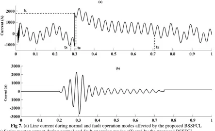
The fig 7 (a) and (b) shows line and reactor current when BSSFCL is connected in the network when there no fault he reactor charged with c voltage
The BSSFCL offers negligible impendence and small ripple as shown in fig 7(b). line current.
Fig 7. (a) Line current during normal and fault operation modes affected by the proposed BSSFCL (b) Series reactor current during normal and fault operation modes affected by the proposed BSSFCL
The fig8 shows load voltage during dc mode and ac mode i.e. no fault and fault condition. In the fault condition, the voltage decreases to zero. At t9 the fault is cleared but BSSFCL certain delay given to discharge the across the load it changes its topology from ac to dc.
Fig 8. Electrical load voltage during normal and fault operation modes while the proposed BSSFCL is connected in series with the feeder.
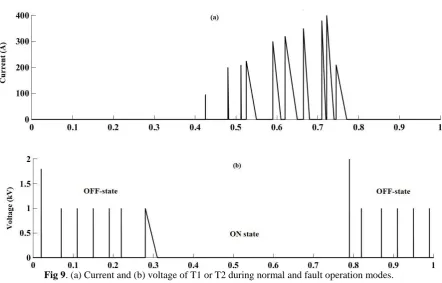
Fig 9. (a) Current and (b) voltage of T1 or T2 during normal and fault operation modes.
The comparative study of the suggested BSSFCL with the FCLs in [7]–[15] shows its superior characteristics over other FCLs. The advantages of the proposed BSSFCL in comparison with other dc reactor-type FCLs, can be stated as follows.
• Comparing the BSSFCL with other FCLs presented in [7]–[15], the proposed BSSFCL uses only one reactor to control the fault current amplitude with its high inductance, which enables better operation by changing the topology from the dc mode to the ac mode, less power loss in the steady state, very fast response to fault occurrence, and the consistency of fault current suppression.
• Even though the dc reactor is inserted in series with the line between the voltage source and the load, it does affect the steady-state performance of the network.
• The configuration of the proposed BSSFCL is simple and reliable.
• Considering its simple control or detection circuit, the application of a single reactor for dc and ac operation modes and available power-electronic switches, the total cost of the proposed BSSFCL has considerably decreased.
In addition, the proposed BSSFCL offers the following advantages that warrant it over the dc reactor-type FCLs, SCFCLs, and Is-limiters.
• Compared to the Is-limiter [23], the suggested SSFCLCB has no special maintenance after switching. • Compared to superconductive FCL [24], no costly cooling system is required.
• Compared to the dc reactor-type FCL, switching overvoltage is decreased and the BSSFCL current-limiting capability is higher. The development of the proposed single-phase BSSFCL to three-phase BSSFCL is easy. The three-phase version consists of three similar single-phase structures of the BSSFCL, and they can independently operate in each phase of the network.
VII.
Conclusion
References
[1]. J. Hill and K. Behrendt, “Upgrading power system protection,” IEEE Ind. Appl. Mag., vol. 15, no. 5, pp. 32–42, Sep./Oct. 2009. [2]. O. C. Onar, J. Kobayashi, and A. Khaligh, “A fully directional universal power electronic interface for EV, HEV, PHEV
applications,” IEEE
[3]. P. N. Vovos, H. Song, K.-W. Cho, and T.-S. Kim, “A network reconfiguration algorithm for the reduction of expected fault currents,” in Proc.IEEE Power Energy Soc. Gen. Meeting, 2013, pp. 1–5.
[4]. S.-H. Lim, H.-S. Choi, D.-C. Chung, Y.-H. Jeong, Y.-H. Han, T.-H. Sung, and B.-S. Han, “Fault current limiting characteristics of resistive type SFCL using a transformer,” IEEE Trans. Appl. Superconduct., vol. 15, no. 2, pp. 2055–2058, Jun. 2005.
[5]. J. Pourhossein, G. B. Gharehpetian, and S. H. Fathi, “Unified Interphase Power Controller (UIPC) modeling and its comparison with IPC and UPFC,” IEEE Trans. Power Del., vol. 27, no. 4, pp. 1956–1963, . 2012.
[6]. L. A. Kojovic, S. P. Hassler, K. L. Leix, C. W. Williams, and E. E.Baker, “Comparative analysis of expulsion and current-limiting fuse operation in distribution systems for improved power quality and protection,”IEEE Trans. Power Del., vol. 13, no. 3, pp. 863– 869, Jul. 1998.
[7]. A. Heidary, H. Radmanesh, S. H. Fathi, and G. B. Gharehpetian, “Seriestransformer based diode-bridge-type solid state fault current limiter,” Frontiers Inf. Technol. Electron. Eng., vol. 16, no. 9, pp. 769–784, 2015.
[8]. T. Ghanbari and E. Farjah, “Development of an efficient solid-state fault current limiter for microgrid,” IEEE Trans. Power Del., vol. 27, no. 4, pp. 1829–1834, Oct. 2012.
[9]. H. Radmanesh, S. H. Fathi, and G. B. Gharehpetian, “Novel high performance DC reactor type fault current limiter,” Elect. Power Syst.Res., vol. 122, pp. 198–207, May 2015.
[10]. G. Rashid and M. H. Ali, “A modified bridge-type fault current limiter for fault ride-through capacity enhancement of fixed speed wind generator,”IEEE Trans. Energy Convers., vol. 29, no. 2, pp. 527–534, Jun. 2014.
[11]. H. J. Boenig and D. Paice, “Fault current limiter using a superconducting coil,” IEEE Trans.Magn., vol. MAG-19, no. 3, pp. 1051– 1053, May 1983.
[12]. M. T. Hagh and M. Abapour, “Nonsuperconducting fault current limiter with controlling the magnitudes of fault currents,” IEEE Trans.Power Electron., vol. 24, no. 3, pp. 613–619, Mar. 2009.
[13]. S. B. Naderi, M. Jafari, and M. T. Hagh, “Controllable resistive type fault current limiter (CR-FCL) with frequency and pulse duty- cycle,” Int. J. Elect. Power Energy Syst., vol. 61, pp. 11–19, Oct. 2014.
[14]. M. Firouzi and G. B. Gharehpetian, “Improving fault ride-through capability of fixed-speed wind turbine by using bridge-type fault current limiter,” IEEE Trans. Energy Convers., vol. 28, no. 2, pp. 361–369, Jun. 2013.
[15]. T. Ghanbari, E. Farjah, and A. Zandnia, “Development of a high-performance bridge-type fault current limiter,” IETGen.,Transm. Distrib.,vol. 8, no. 3, pp. 486–494, 2014.
[16]. H. Radmanesh, H. Fathi, and G. B. Gharehpetian, “Series transformerbasedsolid state fault current limiter,” IEEE Trans. Smart Grid, vol. 6, no. 4, pp. 1983–1991, Jul. 2015.
[17]. H. Arai, M. Inaba, T. Ishigohka, H. Tanaka, K. Arai, M. Furuse, and M. Umeda, “Fundamental characteristics of superconducting fault current limiter using LC resonance circuit,” IEEE Trans. Appl. Superconduct., vol. 16, no. 2, pp. 642–645, Jun. 2006. [18]. H. Wu, L. Yuan, L. Sun, and X. Li, “Modeling of current-limiting circuit breakers for the calculation of short-circuit current,” IEEE
Trans.Power Del., vol. 30, no. 2, pp. 652–656, Apr. 2015.
[19]. T. Papallo, M. Valdes, and G. Roscoe, “Predicting let-through arc-flash energy for current-limiting circuit breakers,” IEEE Trans. Ind. Appl., vol. 46, no. 5, pp. 1820–1826, Sep./Oct. 2010.
[20]. C. Meyer and R. W. De Doncker, “LCC analysis of different resonant circuits and solid-state circuit breakers for medium-voltage grids,” IEEE Trans. Power Del., vol. 21, no. 3, pp. 1414 -1420, Jul. 2006.
[21]. M. T. Hagh and M. Abapour, “Non-superconducting fault current limiters,” Eur. Trans. Elect. Power, vol. 19, pp. 669–682, 2009. [22]. D. Dujic, G. K. Steinke, M. Bellini, M.Rahimo, L. Storasta, and J. K. Steinke,“Characterization of 6.5 kV IGBTs for high-power
mediumfrequencysoft-switched applications,” IEEE Trans. Power Electron., vol. 29, no. 2, pp. 906–919, Feb. 2014.
[23]. M. Steurer, K. Frohlich, W. Holaus, and K. Kaltenegger, “A novel hybrid current-limiting circuit breaker for medium voltage: Principle and test results,” IEEE Trans. Power Del., vol. 18, no. 2, pp. 460–467, Apr.2003.