and do the jobs that we would normally do manually. Home automation takes care of a lot of different activities in the house. The objective of this project is to enable users to remotely control their home appliances and systems using a cell phone-based interface. To access the control unit, the user should send an authentication code along with the required/desired function/action to his/her home control system via Mobile. Upon being properly authenticated, the cell phone-based interface at home (control unit) would relay the commands to a microcontroller that would perform the required function/action and control the device using relays. So, that we can control devices sitting at a remote place.
Keywords: DTMF (Dual Tone Multi Frequency), Microcontroller Based, Automation, Appliances Control, Mobile Network, Wireless Communication, Proteus Simulation
________________________________________________________________________________________________________
I. INTRODUCTION
The home automation has many features makes the home owner remotely toggle appliances such as air conditioning and heating units, lamps or porch lights, landscape sprinkler timers, snow-melt systems, outdoor property lighting, and safety lighting.
The main aim of the design provided in this project is to develop a device to have wireless control of home electrical appliances. The device can be made sure to be available at a low cost so that everyone can afford it. This is basically a device built for home appliances control system that can provide remote access to house hold electrical appliances at low cost and in efficient way. The electrical devices connected in the home, office or any place, consume electrical power, and there is an absolute necessity of saving of power as per present day situations. So, it is necessary to control electrical devices more effectively and efficiently at anytime from anywhere. So, this project is built for the sole purpose of efficient control of electrical appliances.
This project is basically built on the process of wireless communication through the DTMF Signaling. DTMF plays a very important role in the present-day life of a person. Each and every person now-a-days has a cell phone with him. So as technology is increasing so vastly now-a-days, everything in the world is being automated and wireless for the comfort of man. So here we are building a device based on the DTMF signaling to control the electrical appliances through a cellular phone. Here we are going to design a cell phone based remote control of electrical appliances. This system is designed for controlling arbitrary devices according to the necessity. It includes a cell phone which is connected to the designed system. Basically, for the system to work a phone call is made to the designated number is being sent containing a password. As the caller press the specific password, it results in turning ON/OFF of the particular device. The switching of devices is achieved by relays.
II. DTMF SIGNALING
DTMF generation is based on a 4×4 grid matrix shown in Figure 1. This matrix represents 16 DTMF signals including numbers 0–9, special keys * and #, and four letters A–D. The letters A–D are assigned to unique functions for special communication systems such as the military telephony systems.
The DTMF signals are based on eight specific frequencies defined by two mutually exclusive groups. Each DTMF signal consists of two tones that must be generated simultaneously. One is chosen from the low-frequency group to represent the row index, and the other is chosen from the high-frequency group for the column index.
Fig. 1: Telephone Keypad Matrix
III. CIRCUIT DIAGRAM AND DESCRIPTION
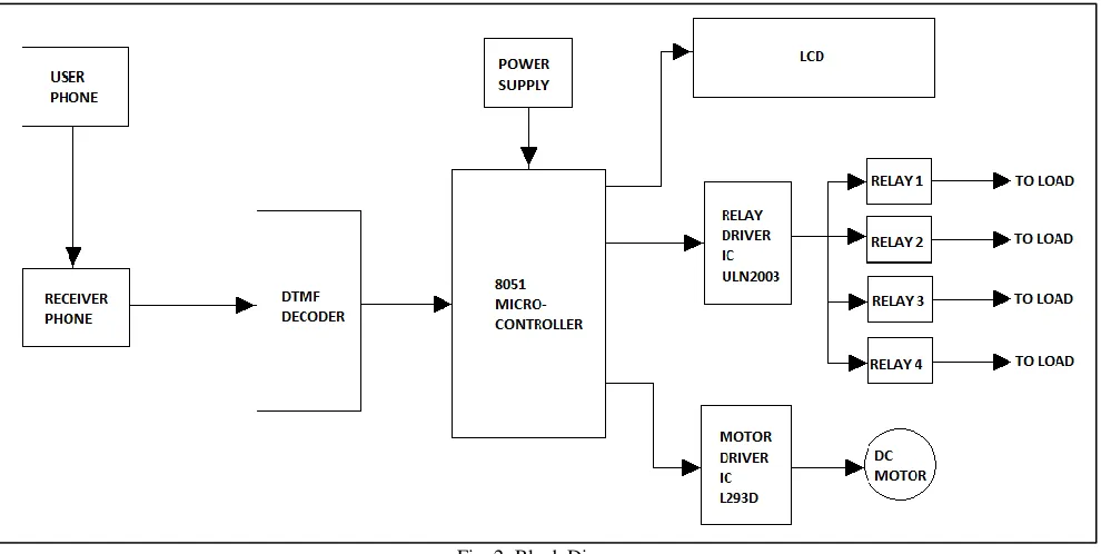
Block Diagram
Fig. 2: Block Diagram
The block diagram of our project is shown below in the fig 2. it is an outline description of how we have implemented our project and the various steps involved in it. From the block diagram given below, the first mobile station is used as a transmitting section from which the user sends a code that contains commands and instructions to the second mobile station which is based on a specific area where our control system is located, through DTMF. The received code is in DTMF format which is send to the DTMF decoder connected via headset jack of the phone.
The DTMF decoder converts it into digital signal and sends it to the microcontroller interfaced to it. Then the microcontroller processes the code and carries out the specific operations. The ULN2003 is used to drive the relay circuits which switches the different appliances connected to the interface. And L293D is control the dc motor according to the signal receiving from the microcontroller. And LCD shows the output of the microcontroller or status of load.
After connecting the circuit properly and assuming all the connections are right the following steps are to be followed: The remote user calls on receiving phone and press authenticated commands in phone keypad.
Through the DTMF the signal is received by the receiver phone on the device.
That DTMF signal is passed to the DTMF decoder to convert it to the digital signal, and it sends them to microcontroller. Microcontroller issues commands to the appliances and the devices connected will switch ON/OFF and shows the status of
port (P1.0 to P1.3 respectively) (which is considered as an input port) through the AND gate IC 7408 (which used for the logical transformation)
Interfacing of Relay driver IC ULN2003 with AT89C51
Connect the ground terminal to the ULN2003 pin number 8 and connect the 12V DC supply to the pin number 9 of the ULN2003, the output of the microcontroller is on P0 port (here P0 port is considered as an output port).
Port P0.0 to P0.3 of the microcontroller is connected to the ULN2003 on pin number 1 to 4 respectively (connection is done though the pull up resistor as the AT89C51 is not have an internal pull up on port P0)
SPDT Relay (12V DC) Connection
Here we use 4 SPDT relay for the operating of AC load. This Relay operated on 12V DC and its contact capacity is 230V, 50 Hz AC.
There are mainly five terminals of the SPDT relay, namely called as C1, C2, C, NO, & NC. C1 is connected to common 12V DC supply (on pin 9 of ULN2003) and the C2 is connected to the output pin of the ULN2003.
AC Load (with capacity 230V, 50Hz, 7A AC supply) across the terminal C and NO of the relay.
Interfacing of motor driver IC L293D with AT89C51
Connect the supply and ground terminal of the IC L293D as its datasheet represented. Connect the P0.4 and P0.5 of the AT89C51 to the Pin number 2 and 7 (input logic pin) of the L293D and connect the DC motor across the pin number 3 and 6 of the L293D
Interfacing 16x2 LCD with the AT89C51
Connect the Pin number 1 and 3 of the LCD to the Ground terminal and connect the 5v supply to the Pin 2 of the microcontroller. Connect the Pin 4,5 and 6 to the Port P3.5, P3.6, and P3.7 respectively.
Connect the data pin 7 to 14 of the LCD to the Port P2.0 to P2.7 respectively
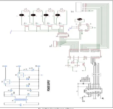
AT89C51
Fig. 3: Main Circuit Diagram of Project
Table - 1 List of main components
Equipment Device and It’s ratting 8051 microcontroller IC AT89C51
DTMF Decoder MT8870
Relay SPDT
Relay Driver IC ULN2003
DC motor 12V
Motor Driver IC L293D
Transformer 230/12V
Audio jack 3.5mm
In Addition to these a cellular phone is required which has to be connected to the device to receive the code from the user’s phone. The resistors and capacitors are to be selected according to the ratings of these equipment selected and also for the efficient performance of the device.
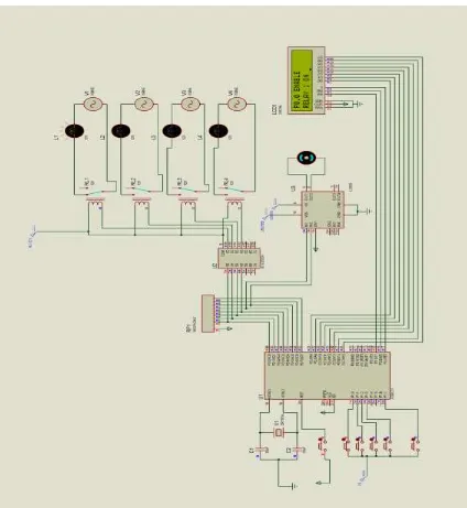
Fig. 4: Simulation circuit with output result
Proteus software has been used for the simulation of the circuit discussed above. As the DTMF decoder MT8870 is not present in the IC’s given in the simulation, 8051 microcontroller is programmed to use as the DTMF decoder in this case. The simulation circuit is shown in the given fig.4.
The simulation circuit is build such that, the 8051 microcontroller receives the signal from the keypad (here we use push button as an input logic) through port P1 and it decodes the signal and then as per the authenticated code, it sends the signal to the relay driver IC and motor driver IC which is connected to the pins P0 ports (through the pull up resistor because AT89C51 has no internal pull up resistor on P0 port) of the micro-controller, and at the same time, the LCD display is being used for the display of the code given by the user, and it is connected to the microcontroller through the port P2.
The code is select to which device to be turned on, user select respected code are pressed for on and off of the devices individually. The simulated output is shown in fig.4.
System features
1) This system can control up to 10 devices, it may be any electric or electronic appliances, and each device is given a unique code.
3) This system doesn’t cost a lot of money, and it’s easy to implement.
4) Its highly secured system using the white list programs on the home-based phone to block any other call from controlling the home appliances.
5) This system can be controlled by multi users, this feature refers to user choice.
V. CONCLUSION
From the convenience of a simple cell phone, a user is able to control and monitor virtually any electrical device in a household. This makes it possible for users to rest assured that their belongings are secure, that the garage door is shut, and that the television was not left running when they left the house to just list a few of the many uses of this system.
REFERENCES
[1] Muhammad Ali, “The 8051 microcontroller and embedded system using assembly and c,” in Pearson Education, second ed. September 2007.
[2] Jadhav ashish, Kumbhar mahesh, Walunjkar Mahesh, “Cell phone controlled applications and systems based on DTMF signaling” in lap lambert academic