A New Error-Correcting Transmission Method
for Dual Ring Fieldbus in CNC System
Lei Yang
School of Computer Science and Technology, University of Science and Technology of China, Hefei, China
Email: [email protected]
Hu Lin
Shenyang Institute of Computing Technology, Chinese Academy of Sciences, Shenyang, China
Email: [email protected]
Dongfeng Yue
School of Computer Science and Technology, University of Science and Technology of China, Hefei, China
Email: [email protected]
Tianrong Gao
Graduate School of Chinese Academy of Sciences, Beijing, China Email: [email protected]
Abstract—For solving the security problems caused by the errors occurred during the real-time transmission of the fieldbus in the CNC system, a new transmission scheme, which involves the error detection and self-correction, was proposed based on the dual ring fieldbus in the CNC system. This scheme specifies a structure of two-way transmission in fieldbus and a data format with self-correcting function as well as related detection and correction method was designed. The result of testing demonstrated that, comparing to the existed method, this scheme excellently met the real-time requirements of CNC system while effectively reducing the retransmission probability and improving the efficiency.
Index Terms—error correction, dual ring fieldbus, real-time performance, retransmission probability, CNC system
I. INTRODUCTION
As the widely using of CNC system in the manufacturing field, it is evolving to be speed, high-precision and high reliable[1]. The significant factors inside are the real-time performance and the secure data communication[2]. They are also the demands for the CNC system fieldbus in which real-time performance and transmission security are essentially foundational. The real-time performance guarantees data’s arrival to stations in time and data security ensures safety of system by avoiding accidents. Therefore, the improvement on these two parts is quite significant[3].
In the past, the key point of transmission security research is focused on optimization of fieldbus structure, error detection, the enhancement of retransmission efficiency and so on. However, retransmission would result in delay in the data exchanging which would badly, if lacking an efficient self-correcting method, influent the system real-time performance.
For solving these problems, this article designs a dual ring safe transmission scheme, which has implemented self detection and correction in a single cycle time that reduces the retransmission probability on the condition that satisfied the requirement of real-time performance, while communicating between master and secondary stations.
II. RESEARCH BACKGROUND
At present the safety research of fieldbus in CNC system is concentrated on fault protection protocols, which are committed to error detecting and feedback transmitting, just like FF, PROFIBUS and CANBUS[4] does. Those fieldbus protocols support secure communication within fault detection such as Profisafe[5], in which data are encrypted, and CANopen safety with Safeguard Cycle Time[6].
In Profisafe, the data to be sent will be preprocessed in the master station. Before it is formatted, the encryption algorithm picks up the information of both bit streams and current situation variables to generate secure keys. The master station sends the keys with the encrypted data to the secondary stations. While secondary stations receive the encrypted data, they first fetch the keys, and This work is supported by the Chinese National Projects for Science
then use the keys to verify the data. If the data is transmitted accurately, they will be decrypted and accepted by the stations. But if there are errors, the decryption will fail, and then the secondary stations report to the master and request retransmission.
The CANopen protocol provides another safe-guaranteed method[7]. In the station a timer is set to count the transmission time. It has a standard safe time in every initialization and after the data is sent, the timer launches[8]. If the master station receives the feedback of secondary stations in time, it means that the transmission is correctly working. If the transmission is time-out or even the feedback has not been received, which means one or more stations may interrupt, the circuit will reform immediately and the data will retransmitted[9].
In general, both the protocols focus on protecting connectivity of message exchanging among stations and reliability of feedback that transmitting to ensure whenever error occurred the master is able to keep connection with secondary stations to receive feedbacks in order to start retransmission. On the one hand, it guarantees errors could be found and then corrected, however, on the other hand, retransmitting frequently will increase the workload of master station and also waste extra communicating rounds in sending repetitious data which would lead to delays, even interruptions in the working duration[10].
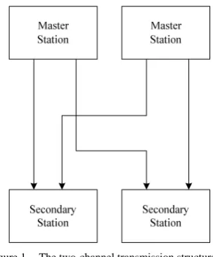
Fig. 1 shows the two-channel transmission structure. It is widely used in the industrial fieldbus [11].
Figure 1. The two-channel transmission structure
This structure has two or more master stations working in the system. In each cycle time the same data will be sent to a station in separated circuits[12]. One may lost during the transmission while another one will arrive to the destination successfully. It keeps double redundancies in transmission and enhances the security[13].
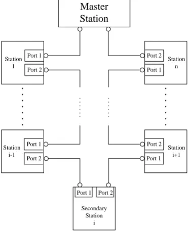
Further more, a multi-fieldbus scheme with sorts of transmitting technologies is defined[14]. To meet the demand of respective real-time performance, it differentiates high speed and low speed stations in different fieldbus and adopts kinds of safe communication methods as shown below.
Figure 2. The structure of multi-fieldbus scheme.
The multi-fieldbus scheme separates a mount of stations by disparate fieldbus, minimizing the station number in a single ring[15]. It shortens communication cycle time and reduces the badly influence of retransmission. Nevertheless, integrating various fieldbus protocols into a system is quite a complicated scheduling for master station, especially in which data has to be formatted specifically in each communication cycle time[10]. Even more, when the number of stations isn’t so gigantic, the multi-fieldbus scheme rarely enhances the systematic performance. For this reason, problems still exist.
III. THE DUAL RING SELF-CORRECTING TRANSMISSION
SCHEME
Considering the shortages of existing schemes about data transmission in fieldbus, this article proposes a self-correcting transmission method based on dual ring structure of fieldbus. It allows two-way transmitting between master and slaves and carries out both error detection and self correction in a single cycle time without retransmission so frequently.
A. Dual Ring Topological Structure
Master Station
Secondary Station 1
Secondary Station n
Secondary Station i-1
Secondary Station i
Secondary Station i+1 Ring 1
Ring 2
Figure 3. The topological structure of dual ring fieldbus.
The next figure shows the abstract communication structure of dual ring fieldbus in CNC system. Both master and secondary stations have two ports which form a ring connectively one by one. The master sends Ring 1’s packet in port 1 and the other in port 2. If two packets achieve the same secondary station, they will be handled in the manner of FIFO[17].
Master Station
Port 1
Port 2 Station
1
Station i-1
Secondary Station
i Port 1
Station i+1 Station
n Port 2
Port 1
Port 2
Port 1 Port 1
Port 2
Port 2
Figure 4. The communication structure of dual ring field bus.
B. Self Correction Method
In the communication, the data are not sent directly, instead they are packed to the fixed format[18] in order to be get and set correctly.
The packet format is defined as below:
Figure 5. The format of packets in the rings.
Protocol Header: the header information contained in an packet for the current transmitting protocol of fieldbus. Ring Num: The distinctive sign of rings to the packets. Packet Capacity: the number of data contained in Packet Payload.
Sequence Num: the number generated by master station every time a new cycle starts to maintain consistency with secondary stations.
Packet Payload: the field consists of data ordering by Station Num from which secondary stations would fetch the data.
As seen above, the Protocol Header, Ring Num and Sequence Num are the control field[19]. They are used to be recognized by the secondary stations for which ring it comes from and which cycle it belongs to. All the information would be saved by the secondary stations to keep synchronous with the master. The Packet Capacity is an important part of the self-correction operation. Stations use it as the base number of the selection of related data.
The Packet Payload is the data field of the packet[20]. It has the data sending to the secondary stations and the data in the Packet Payload also have been formatted by the master station as below:
Figure 6. The data format in Packet Payload.
Station Num: the mark of the secondary station it’s sending to.
Data Field: the content of Packet Payload.
CRC: Checking for the errors occurred in transmission duration.
The Station Num of the data is used to be distinguished by the station. It is also made use of the self correction as the label of each data. CRC checking is a part of the self detection and it is always invoked before stations fetch the instruction from the Data Field to judge if there are errors in the data[21].
⊕
⊕
⊕
Ring 1
Ring 2
1
d d2 d3
1
d′ d2′ d3′
1 3
(d ⊕d ) (d2⊕d3) (d1⊕d2⊕d3)
Figure 7. The generation of self-correcting data.
⊕
⊕
Ring 1
Ring 2
1
d d2
1
d′ d2′
1 2
(d ⊕d ) (d2)
Figure 8. The generation of the last two self-correcting data.
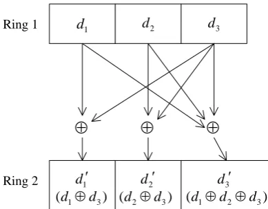
Fig. 7 has overleaped the Sequence Num, Station Num and other unnecessary descriptions in order to pay attention to the executing procedure. In Ring 1 it’s the original data in the payload and the results are put into the payloads in Ring 2. Especially if the number of secondary stations is not multiples of 3, some extra operations are needed. If only one more, directly put its original data into the payload of self correction packet without XOR operation. If two more, just do XOR once with the two original data, and then put the result and final original data into the last positions of the payload.
Finally, data in the payload of Ring 2 should be performed as (1) and (2). The variable with quote stands for the self-correction data in Ring 2 and others signify the original data in Ring 1. The subscript
i
means Station Num which the data belongs to. In an integrated cycle time, it does m+m/ 3 times XOR operations at most, so time complexity is low to O m( )which means all the operations could be accomplished in constant time and has no bad effects on real-time performance.2
1
2 1
, 3 2;
' , 3 1; [ 0, ]
3 , 3 ;
i i
i i i
i i i
d d i k
m
d d d i k k
d d d i k
+ +
− −
⊕ = −
⎧
⎪ ⎢ ⎥
=⎨ ⊕ = − ∈ ⎢ ⎥
⎣ ⎦
⎪ ⊕ ⊕ =
⎩
(1)
1, if is the last but one; '
, if is the last one;
i i
i
i
d d i
d
d i
+ ⊕ ⎧ = ⎨
⎩ (2)
A whole working process of the master station is shown as below:
Start
Initialization, confirm the state of each secondary station and the sequence number of current cycle.
Acquire the data to be sent and verify its destined station.
Invoke the correcting method to compute self-correcting data and pack them to the fixed format.
Send the original packet to Ring 1 via Port 1 and the self correction packet to Ring 2 via Port 2.
Wait for the packets’return.
Are there errors in the data?
Start to retransmission. Prepare for the next
communication.
End
Yes No
Figure 9. The flow chart of the master station
C. Self-Correcting Transmission Scheme
After both packets of two rings have been generated, master station sends the original packets to Ring 1 through Port 1 while the other to Ring 2 through Port 2. A secondary station receives the packet from its neighbor and fetches the data belonging by comparing Station Num and Port Num.
1 2
i i i
d =d+′⊕d+′
mod 3 1
i =
1 1
i i i
d =d+′⊕d−′ 1 2
i i i i
d =d−′⊕d−′⊕d′ di=di′ di=di′ di=di+1′⊕di′
Figure10. Note how the caption is centered in the column.
At the beginning of correction, it does the modulus operations for the next step due to the remainder. Supposing
SN
is the Station Num of current station andR
is the remainder, thenR
=
SN
mod 3
.
1 2
2
1 2
' ', 1;
' ', 2;
' ' ', 0;
SN SN
SN SN SN
SN SN SN
d d R
d d d R
d d d R
+ +
+
+ +
⊕ =
⎧ ⎪
=⎨ ⊕ =
⎪ ⊕ ⊕ =
⎩
(3)
' 1',if is the last but one;
', if is the last one;
SN SN
SN
SN
d d SN
d
d SN
+
⊕ ⎧ = ⎨
⎩ (4)
Equation (3) and (4) shows the specific operations.
d
is the original data needed to be restored andd
′
on the right is self-correction data fetched from the packet in Ring 2. According to do XOR operation to related data, secondary station will get original data back, then set status bit to zero again.Specifically if self correction data has lost or CRC checking fails, correction is infeasible, secondary station must request retransmission. Fig. 10 detailed describes the self-correcting process in a secondary station which Station Num is
i
and Packet Capacity (the number of all the secondary station) isn
.Because of the status bit stations can acquire the state of transmission, if no errors, the packet can be passed to
next station without delay. It guarantees the real-time performance in comparison to other existed methods. Otherwise, the self correction data is separated from original data, so it is able to restore sequential data errors. Only if both the original data and self correction data go wrong, the station just requests retransmission. The retransmission probability has been brought down greatly in this new method.
IV. PERFORMANCE ANALYSIS
Experimental facilities include one master station and five secondary stations. Configuration of master station is 800 MHz Loongson CPU and 512 MB RAM. Transmission Medium is 100Mb/s fieldbus. The size of packet is 20 Bytes, cycle time is set to 1 ms.
A. Real-Time Performance Test
Real-time performance is the basic requirement, if in a transmitting process the information data could not be sent to stations in time, as a result system may terminate accidentally. For this reason, the real-time performance is one of the important terms in the transmission scheme of fieldbus. In this test, the performance in the master and secondary station are recorded separately.
both two channel transmission scheme without self correction and self-correcting transmission scheme, will be recorded. By comparing the proportion that delaying time to the cycle time in these two schemes, the influence of self correction method to the real-time performance will be shown.
Figure 11. The delay of secondary stations in two-channel transmission.
Figure 12. The delay of secondary stations in dual ring self-correcting transmission.
Figure 13. The delay of master station in two-channel transmission.
Figure 14. The delay of master station in dual ring self-correcting transmission.
The test shows that the self correction scheme is not so far different from two channels transmission scheme on the average executing time in stations. In master station, it takes some time to do the exclusive OR operations. The delay in each secondary station is less than 2%, so it can well meet the real-time requirement.
TABLE I.
THE AVERAGE DELAY OF STATIONS AND CYCLES
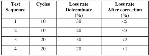
B. Recovery Capability Test
While testing the restoring efficiency of self- correction method, master station will send packets within determinate loss rate. After transmissions accomplish, the restored loss rate will be recorded. By comparing loss rates in different loss rates and cycle numbers before and after, the validity of self correction method will be shown.
TABLE II.
THE REPAIR RATES OF SELF-CORRECTING METHOD
As can be seen from the table above, the effect of self correction method shall enhance as increasing of cycles and the method is able to restore most data losses effectively in different loss rates. The recovery capability of the method is admirably testified.
C. Consequence
From the tests, the self-correcting method in dual ring fieldbus is proved to be able to meet the requirement in the efficiency of transmission, but also the demand in the self correction.
Comparing to the two-channel transmission, the self-correcting method has no significant differences in the execution time of the secondary stations. But it spends much more time on master station. That’s because of the additional XOR operations and accompanying data search and access. Each XOR operation does at least two data search. If the data are not sequential, even more time will be wasted on finding these related data.
The self correction method is able to restore most errors on the condition that the self-correcting data are unbroken. If that, the correction will be completed. But if the original data and the self-correcting data are both lost, the correction isn’t able to continue which is the shortage should be covered.
V. CONCLUSION
In this article a self-correcting transmission scheme is proposed based on dual ring fieldbus in CNC system to meet the requirements of both real-time performance and
Average delay(μs)
Secondary Master Cycle time
Two channel 3.6645 10.6046 182.5637
Dual-ring 3.8422 13.8542 203.9815
Test Sequence
Cycles Loss rate Determinate
(%)
Loss rate After correction
(%)
1 10 30 <5
2 10 20 <3
3 20 30 <2
security communication. In the scheme the dual ring structure is used to transmit information in the fieldbus, a self correction method is designed to generate correction data by processing the original data. The self-correcting data are able to restore the errors independently. These two data are packed to the fixed format with control field and it can be accessed by the secondary stations. The packets are sent in two rings through different ports. Both error detection and correction can be accomplished in a single cycle time. The tests prove that, with tolerable increasing on the master stations’ workload, the scheme meets the real-time demand of CNC system. It decreases the retransmission probability effectively as well. The follow-up will be focused on the research of safety communication protocols and error detection and correction method to meet the security requirement of fieldbus in Numerical Control system.
ACKNOWLEDGMENT
We would like to thank Shenyang Golding NC Tech. Co., Ltd. Funding for this research was provided by the Chinese National Projects for Science and Technology Development 2011ZX04016-071.
REFERENCES
[1] MIGUEL G. Safety over EtherCAT: the safety solution for EtherCAT[EB/OL].[2010-01-22].
http://www.ethercat.org/pdf/english/pcc0107_safety_over_ ethercat_e.pdf.
[2] JARMO A, MARITA H, TIMO M. “Safety of digital communications in machines” [EB/OL]. [2010-01-22]. http://www.vtt.fi/inf/pdf/tiedotteet/2004/T2265.pdf. [3] WU Qin, QIN Qiang. “Analysis of implementation of the
safety function in CC-Link safety net work”. Automation Panorama, 2007, 24(2): 36-38.
[4] REXROTH B, HUMPHREY D W. “Safe motion
technologies: competitive advantages for early adopters” [EB/OL]. [2010-01-20].
http://www.plantservices.com/Media/MediaManager/rex_r oth_safe_motion.pdf.
[5] WU Chengyan. “The research and analysis of safety bus protocol-profisafe”. Beijing: Beijing Jiaotong University, 2006.
[6] RAHMANI M, HINTERMAIER W, RATHGEBER B M. “Error detection capabilities of automotive network technologies and Ethernet-a comparative study”. IEEE Intelligent Vehicles Symposium, 2007, 13(15): 674-679. [7] DZUNG D, NAEDELE M, HOFF T P V, et al. “Security
for industrial communication systems”. Proceedings of the IEEE, 2005, 93(6): 1152-1177.
[8] Dempsey B J, Weaver A C. “On retransmission-based error control for continuous media traffic in packet-switching network”. Computer Networks and ISDN Systems, 1996, 28(5): 719~736.
[9] ITU-T Recommendation H. 323. “Packet based multimedia communications systems”. 1998.
http://www.databeam.com/Standards/H323/H323_Primer.h tml.
[10]C. Schwaiger and A. Treytl, “Smart Card Based Security for Fieldbus Systems”, 2003 IEEE Conference on Emerging Technologies and Factory Automation, Lisbon, 16-19. Sep. 2003, pp. 398-406, 2003.
[11]Ch. Schwaiger and T. Sauter, “Security Strategies for Field Area Networks”, 28th Annual Conference of the IEEE Industrial Electronics Society (IECON), Sevilla, 5.-8. Nov.2002, pp.2915-2920.
[12]T.Sauter and Ch. Schwaiger, “Achievement of secure Internet access to fieldbus systems”, Microprocessors and Microsystems, 26(2002), pp. 331-339.
[13]Boterenbrood H. CANopen: Hign Level Protocol for CAN-bus[Z]. 2000
[14]CAN in Automation, CANopen Specification.
[15]R.Bosch GmbH, Controller Area Network Specification: Version2. 1991
[16]CAN in Automation, CiA DSP 304-V1.0.1: Framework for safety-relevant communication, 2004
[17]Jungandreas, F., “The CANopen Safety Chip”, CAN Newsletter, 4/2003.
[18]Liu Cuiqing, Ping Xijian and Zhang Tao, “A Research on Steganography Method Based on Error-correcting codes”,
Proceeding of the 2006 International Conference on Intelligent Information Hiding and Multimedia Signal Processing (IIH-MSP’06), 2006.
[19]Wang Weixiang, Liu Yujun and Li Wenxiong, “Information Hiding Algorithm in Channel Coding Based on m-Sequence”, Computer Engineering, 2007,(3): 118-122.
[20]R. Ahlswede, B. Balkenhol, and N. Cai, “Parallel Error Correction Codes”, IEEE Trans. Inf. Theory, vol. 48, no.4, pp.959-962, Apr. 2002.
[21]F. J. McWilliams and N. J. A. Sloane, “The Theory of Error Correcting Codes”, Amsterdam, The Netherlands: North-Holland, 1986.
Lei Yang received his Bachelor degree in Computer Science from School of Computer Science and Technology, University of Science and Technology of China, Hefei, China, in 2009. He is currently a Ph.D. candidate at the School of Computer Science and Technology at University of Science and Technology of China. His current research interest is in the area of CNC technology, safety fieldbus and security control system.
Hu Lin(Ph.D.) is a professor in Chinese Academy of Sciences and director of the doctoral school of University of Science and Technology of China. His research interests include CNC technology and real-time system.
Dongfeng Yue received his Bachelor degree in Computer Science from School of Computer Science and Technology, University of Science and Technology of China, Hefei, China, in 2007. He is currently a Ph.D. candidate at the School of Computer Science and Technology at University of Science and Technology of China. His current research interest is in the area of CNC technology, safety fieldbus and security control system.