GSJ: Volume 8, Issue 1, January 2020, Online: ISSN 2320-9186 www.globalscientificjournal.com
Structural Systems in Enveloping a Sport Complex.
Obiri Godwin Ezue
Post graduate student, Rivers State University
Email: [email protected]
Lecturer; Dr. W. G. Brisibe
Department of Architecture, Rivers State University
Nkpolu-Oroworukwo, Port Harcourt
ABSTRACT
Sport is a necessity for the development of sound mind and body which are needed for adequate and balanced education. Besides, it is an international phenomenon with socio-political and economic implication. This has facilitated the need for the development of sport facilities alongside other educational and social facilities in universities to enhance the participation of students in sport activities either as a full time programme as in physical education or as a social and recreational activity. The study involves analysing various structural systems use in enveloping sport facilities. It investigates sporting facilities where light weight structure roofing systems have been achieved at minimal cost or expenditures.
1.0 Introduction
Sports have been a central part of college life since the establishment of the first universities
and schools of higher education. Students and the surrounding community congregate for
athletic contests, intramural activities, and personal fitness on college campuses worldwide.
In recent years Universities have seen that in order to stay competitive with other schools
there is an increased need for larger, more state of the art sports and recreation facilities that
will accommodate the students‟ needs for an attractive and efficient place to work out and
participate in recreational athletic events.
Fabric structures have been in existence for thousands of years. However, only in the last
fifty years have these "tents" evolved into structures utilizing the inherent structural
characteristics of the membrane. While tensioned fabric structures are fascinating to
engineers for realizing materials to their fullest potential, they never cease to amaze the
architect in its free flowing shape and design.
However, due to the nature of membrane structures, a conventional method of design and
analysis does not suffice. Moreover, having a short history of half a century, relatively little
information is available compared to conventional structures. Everything from the material
selection, load considerations to the analysis method and the structural connections must be
designed for the specific needs of the enveloping framework. (Miriam, 2007).
2.0 Methods
For the purpose of this paper, the case study method of research has been adopted.
Secondary sources of information shall be from studies by other researchers through books,
journals, published and unpublished literature, as well as online sources „. It can be used to
of it as long as the data remain relevant. The data collected will be reviewed and used as
bases for concept generation and analysis.
For this paper I have chosen to do two things: summarize empirically validated findings from
other studies that are relevant to the questions of this research and add my own line of
thought.
3.0 Definition of terms
3.1 Roof
A Roof, covering of the top of a building, serving to protect against rain, snow, sunlight,
wind, and extremes of temperature. (https:www.britannic.com/technology/roof, 2019).
3.2 Fabric structure
In architecture, fabric structures are forms of constructed fibres that provide end users a
variety of aesthetic free-form building designs.
Custom-made fabric structure is engineered and fabricated to meet world-wide structural,
frame retardant, weather resistance and natural force requirement.
Fabric structures are tensile structures in which a membrane is stretched to form a
three-dimensional surface that can be used to create a roof, shade, or decorative component.
(https://www.designingbuildings.co.uk/wiki/Fabric_structures, 2019).
3.3 Tensioned fabric structures
Tension fabric buildings are constructed using a rigid frame which can consist of timber,
steel, rigid plastic, or aluminium and a sturdy outer membrane. Once the frame is erected, the
fabric cover is stretched over the frame. The fabric cover is tensioned to provide the stable
Fabric tensile structures is a stretched fabric material in surface tension formed to a
three-dimensional surface that can be used to create a roof, shading, or decorative components by
tensioning it to cables and it is constructed using a specialised fabric under tension to support
self-weight and take care of the live load providing a very cost effective and covering a large
distance without intermediate supports. (
https://theconstructors.org/structural-engg/tensile-fabric-structures-properties-types/25844/, 2019).
4.0 Membrane Structures
Membrane structures, encompassing both the tensioned fabric and the supporting structure,
can span from 3to 20 meters to spans more than 200 meters. For spans more than 200 meters,
the
fabric is supported bycables with steel or air so that unsupported span of the fabric is actually
less than 30 meters. There are several systems adopted for tensioned fabric systems. While
maintaining the concept of tension fabric design, each system is unique. These systems can
be combined with each other to create interesting and even more complex designs. (Karl,
2005).
Membrane structures create spaces that are enclosed by tensioned membranes. At its
simplest, a tent may be regarded as a membrane structure given its steel or fiberglass poles
support a canvas or plastic membrane covering.
4.1 Arch-Supported Structures
The arch-supported membrane shape is comprised of a saddle with one curving boundary and
three curving boundaries. This configuration is conceptually very pleasing since the
membrane working in complete tension while the arch is ideally working in complete
compression. These systems can be designed quite efficiently for spans of about 25feet.
The interaction between the membrane and the arch, which create the saddle curvature of the
achieve this, the arch must be relatively stiff. Using tubular steel members with low bending
stiffness is necessary. (Huntington, 2004)
4.2 Structures with Primary Supports
Saddle surfaces can also be created in the membrane by primary point supports that, unlike
the arch-supported system, do not lie on the same plane. Care must be taken that the cable
stays are in tension regardless the loading.
An example of primary point support structures is the simple cone structure that consists of a
mast in the centre of the membrane. This can be repeated in groups to enclose a larger area of
space. Although this can fulfil many applications and provide the greatest range of shapes,
the existence of a big structural element in the centre of the utilized area can become
awkward and obstructive. (Roland, 1970)
4.3 Ridge-and-Valley Structures
The concept of ridge-and valley structures are based on the creating of slight saddle bylaying
cables in an adjacent pattern with opposing curvature. The membrane is created and
restrained bythe alternating ridge and valley cables.
The curvature created is quite small and therefore this type of structure cannot be realized in
all situations. Many tests and loading scenarios must be reviewed before deciding the
feasibility of this kind of design. (Roland, 1970)
4.4 Mast Structures
In tensioned fabric structures where the supporting structure consists of masts, fabric is
suspended from cables hung off masts or other compression elements. This kind of system is
ideal for long span roofs. There are many forms of mast structures. The main three forms are
the following: masts with hinged supports stabilized with cable stays, masts with hinged
supports stabilized bythe membrane and masts with fixed supports.
The masts must support both axial loading and lateral wind and dead loads (for angled
masts). To resist buckling, which the masts are highly susceptible as a result of the axial
hinged base must be able to initially roll when the masts rotate, but after 2 degrees of
rotation, the hinge must be able to slide. Care must be taken through construction and
materials to ensure that excess friction does not impede this action. (Koch et al. 2004)
Case Study: The bird nest Beijing Olympic Stadium
Owner; Chinese Government
Designed by Herzog and Meuron, Structural engineer; Arup
Location; 1 National Stadium South Road, Beijing, Chine.
Capacity; 91,000 (2008 Olympic), 254,600sqm
Height; 70meters, Width; 296meters, Length; 320meters
Structural Engineer; Ove Arup & Partners.
Construction; 12.2002-06.2008
Cost; $300m
Fig. 1 Floor plan. Photo: Michael Webb © The Architectural Review.
The floor layout of the bird next Beijing Olympic Stadium. The structure defines an
intermediate space between the plaza and the field, the randomness of everyday life and the
ritual of performance. Restaurants, bars, shops and lavatories are integrated within the maze
of the columns at different levels, giving spectators the experience of moving though a
benign version of a Piranesi prison, even as they satisfy prosaic needs.
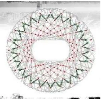
Fig. 2 Roof. Photo: Ali Bacharouche Sadek Saad
The loads at each intersection are split between the members and transferred downward. The
red points indicate the transfer connections were load impact is felt most significantly.
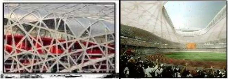
The roof of the bird nest stadium is covered with a double-layer membrane structure (on rigid
steel support), with a transparent ETFE (ethylene tetra-fluoro-ethylene) membrane fixed on
the upper part of the roofing structure and a translucent PTFE (poly-tetra-fluoro-ethylene)
membrane fixed on its lower part.
A PTFE acoustic ceiling is also attached to the side walls of the inner ring.
façade, the inflated cushions are mounted on the inside of the structure where necessary, to
provide wind protection.
5.0 Material characteristics
The selection of membrane material is important to the successful design of the tensioned
fabric structure. The material contributes to the structural function of the system, as well as
other important properties involving durability, insulation, light transmission and fire
protection. Also, the membrane component of the structure determines the long term
appearance of the structure for it is the most visible element of the structure.
Currently, glass and polyester laminates, composites and fluoroplastic films are most popular.
When selecting a membrane, the most important qualities to consider are the mechanical
tensile strength and the elastic properties. Due to this, 90% of all weatherproof tensile fabric
structure projects have used the following three specific membrane materials:
Polytetrafluoroethylene (PTFE), polyvinylchloride (PVC) and ethylenetetrafluorethylene
(ETFE) (Huntington, 2004). These materials are preferable in tensile fabric structures for an
array of reasons. Not only do they have the structural ability to support such structures, these
materials have been in use for the past 50 years and therefore behaviour data of these
materials are abundant. These materials have become standardized and therefore the ease of
acquiring and designing for these materials
are higher than others.
6.0 Membrane Criteria
There are several parameters to consider when selecting the type of membrane fabric to
employ. Ofthese, the most important are the mechanical properties, durability, light
transmission, fire resistance and economic feasibility. For common materials used in
practice, such as PTFE and PVC, material behaviours and characteristics have been well
recorded. However, for newer materials and innovative applications, there are a wide
material.
6.1 Mechanical properties
The mechanical properties of most importance to the designer are the tensile strength, which
measures the force required to rupture the material, tear strength, which is the resistance to
propagate an existing tear, and elastic properties, such as stiffness, which is the relationship
between the modulus of elasticity and the area of the cross section of fibres. (Miriam, 2007)
6.2 Durability
The life span of the membrane structure strongly depends on the durability of the membrane
fabric. Its durability is greatly influenced by the resistance to degrading from UV radiation
and wicking, attacks from organic matter, and the maintaining of seam strength. Vandalism
and soiling can also affect the durability of the membrane. (Miriam, 2007)
6.3 Light transmission
When designing a tensioned fabric structure, great consideration is given to the light
transmission, absorption and reflection of the structure. This will ultimately affect the
appearance and some aspects of the energy behaviour of the structure. (Miriam, 2007)
6.4 Fire resistance
Fire resistance is also an extremely important factor for safety. All materials are required to
undergo the following standard fire tests:NFPA 701 Fire Tests for Flame-Resistant Textiles and
Films (NFPA 1999).
7.0 Fabric Types
The oldest and most commonly used fabrics are coatings or laminates over polyester fabric.
Different kinds of coatings are employed for different desired characteristics. (Miriam, 2007)
Polyvinylchloride (PVC) coated polyester fabrics have been used and tested since the 1960's.
The wide use of this material is due to their low cost, as well as their ease of handle.
However, their life expectancy is only 10-15 years and fire ratings can be improved. The
PVC coated polyester has tensile strength from 350 MPa to 1,200 MPa and a strip tensile
strength of 3,100 N/5cm to 5,800 N/5cm for membranes weighing 800g/m2 to 1,100 g/m2
(Huntington, 2007).
The prestress levels of PVC coated polyester fabric range from 1-4 kN per meter (Shaeffer,
1996). The PVC coating helps the material to achieve high tear strength for the soft PVC
chains around the fibres at the tear to resist further tearing. PVC also has moderate stiffness
as well as moderate behaviour to creep. Although this at times requires pretensioning of the
fabric, the moderate behaviour to creep allows for some flexibility in matching fabricated
components and small errors in fabrication will not result in overstress or wrinkles in the
fabric.
PVC-coating protects the fabric from UV radiation degradation for roughly 10 to 15 years
(Huntington, 2004). Although additional top coats to protect from UV radiation can prolong
the life span of the fabric, it is not very effective. PVC coated polyester can achieve light
translucency of up to 22 percent and although this fabric is not deemed incombustible, it is
classified as a flame retardant. Due to the fact that high temperatures create holes in the
material that allow the smoke and heat to dissipate through the membrane, its incombustible
nature can add to the overall safety of the structure in a fire hazard.
7.2 Polytetrafluoroethylene (PTFE)- coated fiberglass
Another type of membrane fabric commonly used in practice is Polytetrafluoroethylene
(PTFE)-coated fiberglass. This material was developed in 1969 when fiberglass fabric was
coated with Teflon resin. This new material advancement was a landmark in time for tension
fabric structures for it was incombustible, resisted soiling and promised a more durable and
therefore longer life span to membrane structures. However, this material was very expensive
PTFE-coated fiberglass became the material to use in long-lasting iconic architectural
applications, while PVC-coated polyester fabric continued to be used for temporary, portable
structures that can withstand the effects of being repeatedly erected.
The mechanical properties of PTFE coated fiberglass is 3,500 MPa and the strip tensile
strength range from 1,600 N/5cm to 8,800 N/5cm. These strengths allow membranes to
stretch long spans with minimal curvature. However, the tear strength of PTFE-coated
fiberglass is relatively low, having only 80 N to 550 N of strength to resist tears from
propagating. The prestress levels range from 6-8 kN/m, 4-6 kN/m and 1-2 kN/m for heavy,
light and light lining PTFE coated fiberglass fabrics, respectively (Shaeffer, 1996).
Case studies have proved that PTFE-coated fiberglass fabric has an expected life span of over
30 years. Structures, inspected at 30 years of age have no need of replacement due to wear
and degradation. The several coats of PTFE make the fabric nearly unsusceptible to any
damage due to UV radiation as well as chemical attack and wide temperature variation. In
one case study of the La Verne structure erected in 1973, pre-stress levels of the fabric
remained relatively uniform and near the original levels after 6 years (Huntington, 2004).
This shows that the fabric does not creep and distort over time. In fact, the creep was
measured to be only a third of its PVC-coated polyester fabric counterpart. However, there
are negative aspects of this material. Since PTFE-coated fiberglass fabric has low tear
strength, its vulnerability to tears and rips due to vandalism and structural overloading
increases substantially. Also, fiberglass is vulnerable to wicking from edges exposed to
water. However, this can be mitigated by water-repellent coating. The cost of PTFE-coated
fiberglass fabric is quite expensive.
7.3 Ethylene-tetra-fluorethylene (ETFE) film
Films are also used to make up a membrane fabric. In actuality, although the films do not
depend on any property of the woven fabric in the middle, without it, it cannot be considered
a fabric. One commonly used film is ethylene-tetra-fluoroethylene polymer (ETFE). The
These films continue to creep under load, unlike the PTFE-coated fiberglass fabric. The film
yields after elongating 3% and ruptures at 200% of its original length (Huntington, 2004).
This behaviour gives ETFE film very high tear strength. It is possible to use composite
woven fabric in between the film to increase the overall tensile strength.
Although there are limited tests, films, which exclude the performance of the woven centres,
can be expected to endure 15 years facing the environmental elements.
However, the durability, as well as the light transmission, fire resistance and cost, all depend
greatly on the scale and design of the material and structure.
][
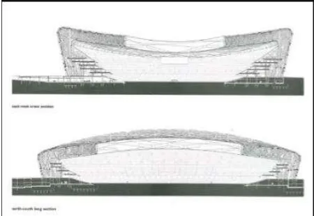
Fig. 3 Section. Photo: Ali Bacharouche Sadek Saad
The core portion of the building carries the dead load of the concrete structure as well as the
live load of people totalling to 13,122 tons. The load id transferred directly to the plinth
foundation as distributed load.
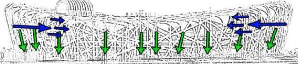
8.0 Horizontal Load
The structure must resist a total of 56,625 tons of vertical load. The Steel structure itself must
resist its own load of 42,000 tons and 11,625 tons of live load, totaling in 53,625 tons. The
Plinth type of the foundation is essential to carry such a load, which is fairly evenly
distributed.
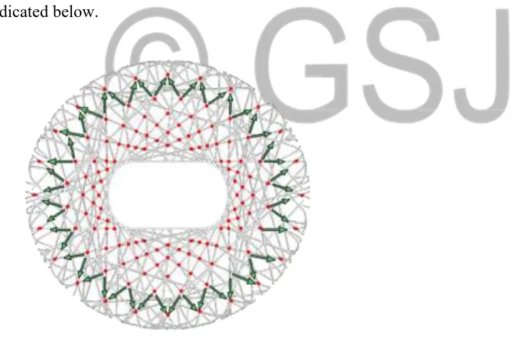
Each member of the steel “Nest” is designed carefully to carry its own weight of 42, 000 tons
loads. The overall shape appears to be random, but in reality it follows strict geometric rules.
The loads at each intersection are split between the members and transferred downward as
indicated below.
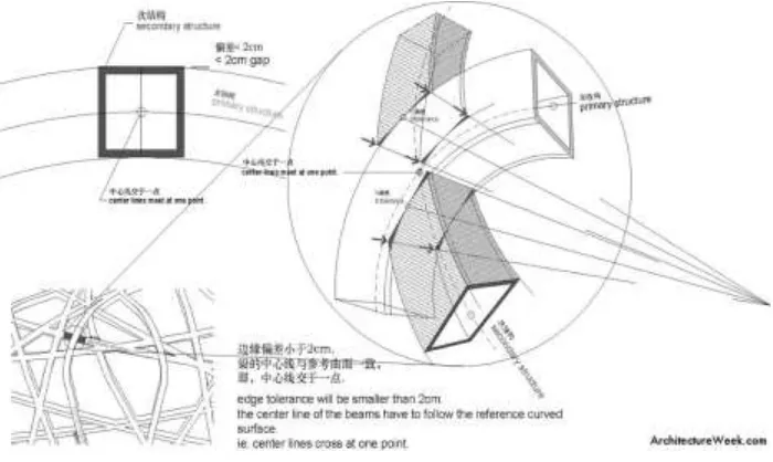
Fig 7 Steel Frame connection details. Photo: Ali Bacharouche Sadek Saad
©ArchitectureWeek.com
The red points indicate the transfer connections were load impact is felt most significantly.
to be welded on two sides of primary members. The steel envelope is constructed of 22.5
miles of steel and it took about 700 welders to complete the task.
Fig 7 Steel Frame connection details. Photo: ArchitectureWeek.com
The core portion of the building carries the dead load of the concrete structure as well as the
live load of people totaling to 13,122 tons. The load is transferred directly to the plinth
foundation as distributed load.
9.0 Lateral Loads
The massive steel structure resists lateral loads in a similar manner as the horizontal ones. In
addition, instead of the loads hitting the structure and following it downwards and upwards it
is broken down through the lattice of steel while being weakened and providing natural
ventilation in the building.
The structural elements mutually support each other and converge into a spatial grid-like
Fig. 5 Steel Structures. Photo: Ali Bacharouche Sadek Saad
10.0 Earthquake Loads
Fig 7 Steel Frame with Earthquake load in mind. Photo: ArchitectureWeek.com
The Beijing National Stadium was designed with earthquake loads in mind, because Beijing
is prone to seismic events. The outer steel structure is completely separate from the inner
stadium seating area and is placed 50 feet apart. this placement allows the two structures
move independently in case of an earthquake. Steel has a rather high modulus of elasticity as
compared to the concrete, therefore the entire outer structure could be put together as a unit
and withstand earthquakes. The core of the stadium was constructed out of the pre-cast
reinforced concrete. Because concrete has significantly lower modulus of elasticity, it was
decided into eight individual sections. this division allows each portion of structure to move
independently of the other in case of seismic motion causing minimal amount of damage.
First set of 24 beams in the form of trusses encircling the concrete bowl. The stadium is
earthquake proof 1000 tons each
The second set of beams fills in the empty spaces of the beams of the first set, they link all
the beams to form a braided structure. The Beijing Bird Nest is designed to withstand
earthquake rated at 8.0 on the Richter scale.
A third set of beams support the stairways that connect the multiple levels and provides a
Fig. 5 Sustainability in the building. Photo: Ali Bacharouche Sadek Saad
The stadium uses geothermal energy to chill and heat water that runs through the HVAC
system. The piping to do that is located beneath the main athletic field.
Maximum amount of natural lighting as possible. The membrane provides rain and wind
protection. It also saves energy. Sunlight filters through the roof to light the building and
keep noise in.
11.0 Conclusion
Though the sport complex is not a new building type, but the information was sort, so as to
gain knowledge. It is hoped that the sport facility will enhance the development of sport in its
environs and also make it possible for people to participate actively in sporting activities.
This research work has identified critical dimensions from which sports participation can be
improved, with the ultimate aim is to provide a permanent solution to the infrastructure
related concerns of sports and thus to highlight the effects of modern materials and methods
in enveloping modern-day design and construction of sport infrastructure, and improving
participants well-being in this facilities. As such, it improves the already existing bulk of
knowledge on modern day roofing materials and sports infrastructural concerns. it has also
primed new dimensions of thought for knowledge discovery and the further promotion of
research as it suggests the opportunity for the provision of facilities for human kinetics and
12.0 References
Barnes, Michael; Dickson, Michael, Widespan RoofStructures,.T. Telford; ASCE Press, Reston; London, 2000.
Huntington, Craig G., The Tensioned Fabric Roof, American Society of Civil Engineers,
Reston, 2004.
Koch, Klaus-Michael; Habermann, Karl J., Membrane Structures: Innovative Building with Film and Fabric, Prestel, Munich; New York, 2004.
Long-span and complex
Structures-www.workgroups.clemson.edu/…/Designing%20for%20long%20Spans-2pdf, 2019 Long span buildings www.britannica.com/EBchecked/topic/83859/.../Long-span-building, 2019
https://www.architectural-review.com/today/national-stadium-in-beijing-by-herzog-and-de-meuron/8690029.article, 2019.
M. Majowiecki: Conceptual design of some long span sport structures", Innovative large span structures, IASS Congress, Toronto, 1992.
M. Majowiecki: Observations on theoretical and experimental investigations on lightweight wide span coverings, International Association for Wind Engineering, ANIV, 1990. Miriam, E. S., (2007) The Design and Analysis of Tension Fabric Structures.
Roland, Conrad, Frei Otto: Tension Structures, Translated by Amerongen, C.V., Praeger, New York, 1970.
S Dong, Y. Zhao, D. Xing- “Application and development of modern long-span structures in china”-Front. Struc. Civ. Eng., 2012, 6(3): 224-239, DOI 10.1007/SI1709-012-0166-6