CPRI v6.0 MegaCore Function User Guide
Last updated for Quartus Prime Design Suite: 16.0
Subscribe Send Feedback
UG-20008
2016.07.22 101 Innovation DriveSan Jose, CA 95134 www.altera.com
Contents
About the CPRI v6.0 IP Core... 1-1
CPRI v6.0 IP Core Supported Features...1-2 CPRI v6.0 IP Core Device Family and Speed Grade Support...1-3 Device Family Support... 1-3 CPRI v6.0 IP Core Performance: Device and Transceiver Speed Grade Support... 1-4 IP Core Verification... 1-5 Resource Utilization for CPRI v6.0 IP Cores... 1-5 Release Information...1-7 Installation and Licensing Features... 1-8 OpenCore Plus Evaluation...1-8 OpenCore Plus Time-Out Behavior...1-8
Getting Started with the CPRI v6.0 IP Core...2-1
Installation and Licensing...2-2 Generating CPRI v6.0 IP Cores...2-2 Files Generated for the CPRI v6.0 IP Core...2-3 CPRI v6.0 IP Core Parameters... 2-6 Integrating Your IP Core in Your Design: Required External Blocks...2-17 Adding the Transceiver TX PLL IP Core...2-18 Adding the Reset Controller...2-20 Adding the Transceiver Reconfiguration Controller...2-21 Adding the Off-Chip Clean-Up PLL... 2-22 Adding and Connecting the Single-Trip Delay Calibration Blocks...2-22 Simulating Altera IP Cores... 2-25 Understanding the Testbench...2-25 Running the Testbench...2-26
Functional Description...3-1
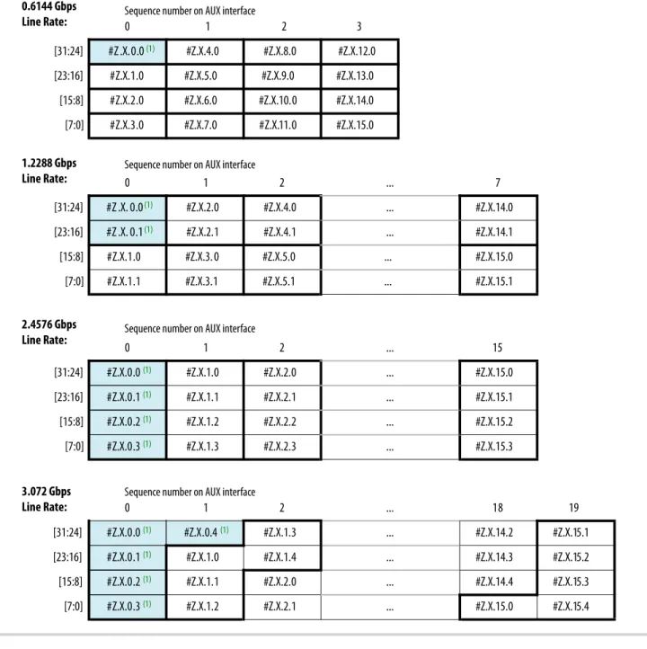
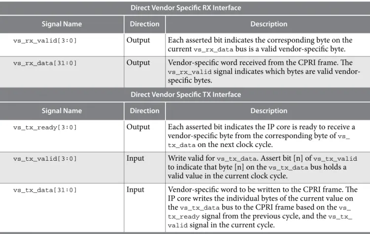
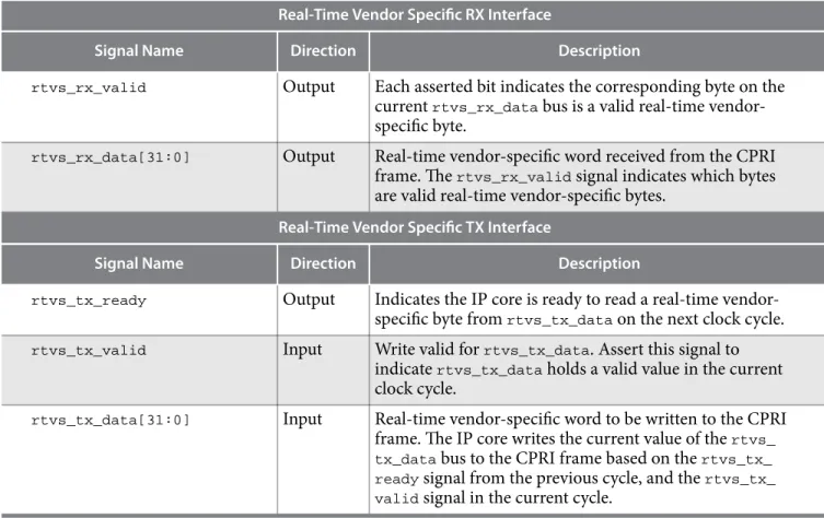
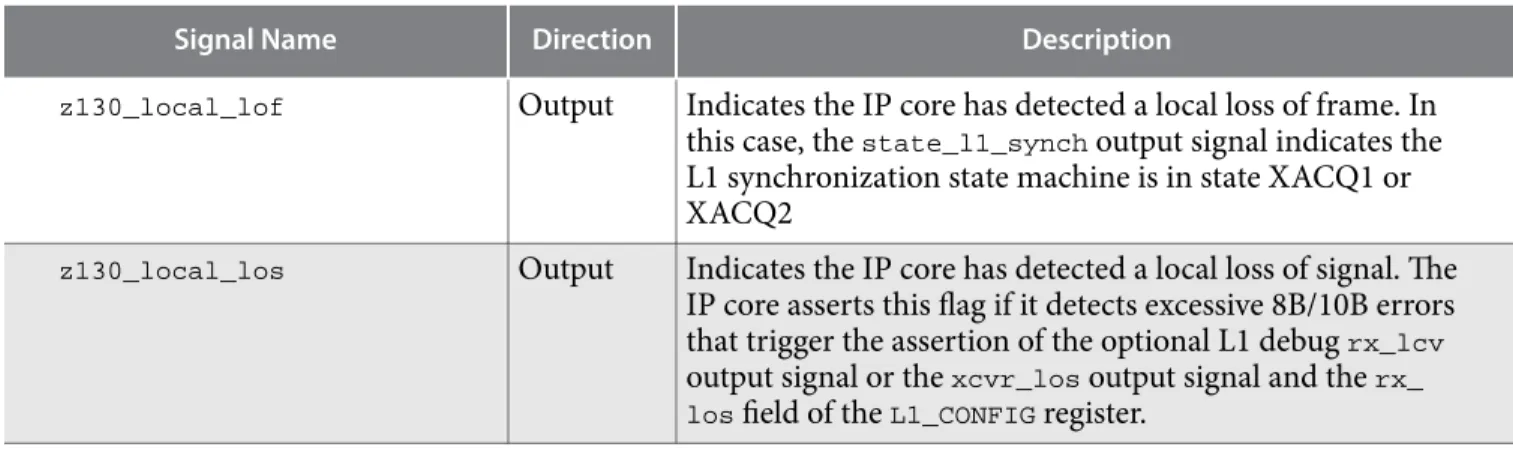
Interfaces Overview... 3-1 CPRI v6.0 IP Core Clocking Structure...3-3 Example CPRI v6.0 Clock Connections in Different Clocking Modes... 3-7 CPRI v6.0 IP Core Reset Requirements... 3-9 Start-Up Sequence Following Reset...3-13 AUX Interface...3-15 AUX Interface Signals...3-16 AUX Interface Synchronization... 3-23 Auxiliary Latency Cycles...3-23 Direct Interface CPRI Frame Data Format...3-24 Direct IQ Interface...3-27 Direct Vendor Specific Access Interface... 3-29 Real-Time Vendor Specific Interface...3-31
TOC-2 CPRI v6.0 MegaCore Function User Guide
Direct HDLC Serial Interface...3-33 Direct L1 Control and Status Interface... 3-35 Media Independent Interface (MII) to External Ethernet Block...3-38 Gigabit Media Independent Interface (GMII) to External Ethernet Block...3-41 CPU Interface to CPRI v6.0 IP Core Registers... 3-43 CPU Interface Signals...3-44 Accessing the Hyperframe Control Words...3-45 Auto-Rate Negotiation... 3-49 Extended Delay Measurement... 3-50 Extended Delay Measurement Interface...3-51 Deterministic Latency and Delay Measurement and Calibration...3-52 Delay Measurement and Calibration Features...3-52 Delay Requirements...3-52 Single-Hop Delay Measurement... 3-53 Multi-Hop Delay Measurement... 3-56 Delay Calibration Features... 3-56 CPRI v6.0 IP Core Transceiver and Transceiver Management Interfaces...3-60 CPRI Link...3-60 Main Transceiver Clock and Reset Signals...3-61 Arria V, Arria V GZ, Cyclone V, and Stratix V Transceiver Reconfiguration Interface...3-62 Arria 10 Transceiver Reconfiguration Interface... 3-63 Interface to the External Reset Controller...3-64 Interface to the External PLL...3-65 Transceiver Debug Interface...3-65 Testing Features...3-66 CPRI v6.0 IP Core Loopback Modes...3-66 CPRI v6.0 IP Core Self-Synchronization Feature...3-67
CPRI v6.0 IP Core Signals...4-1
CPRI v6.0 IP Core L2 Interface...4-1 CPRI v6.0 IP Core L1 Direct Access Interfaces...4-2 CPRI v6.0 IP Core Management Interfaces...4-5 CPRI v6.0 IP Core Transceiver and Transceiver Management Signals...4-7
CPRI v6.0 IP Core Registers...5-1
INTR Register...5-3 L1_STATUS Register... 5-3 L1_CONFIG Register... 5-4 BIT_RATE_CONFIG Register...5-5 PROT_VER Register...5-6 TX_SCR Register...5-7 RX_SCR Register...5-7 CM_CONFIG Register...5-8 CM_STATUS Register...5-9 START_UP_SEQ Register...5-9 START_UP_TIMER Register...5-10 FLSAR Register...5-11
CTRL_INDEX Register...5-12 TX_CTRL Register... 5-13 RX_CTRL Register... 5-13 RX_ERR Register... 5-13 RX_BFN Register...5-14 LOOPBACK Register... 5-14 TX_DELAY Register...5-16 RX_DELAY Register...5-17 TX_EX_DELAY Register...5-18 RX_EX_DELAY Register...5-18 ROUND_TRIP_DELAY Register...5-19 XCVR_BITSLIP Register... 5-19 DELAY_CAL_STD_CTRL1 Register...5-20 DELAY_CAL_STD_CTRL2 Register...5-21 DELAY_CAL_STD_CTRL3 Register...5-22 DELAY_CAL_STD_CTRL4 Register...5-23 DELAY_CAL_STD_CTRL5 Register...5-24 DELAY_CAL_STD_STATUS Register... 5-24 DELAY_CAL_RTD Register... 5-25
Differences Between CPRI v6.0 IP Core and CPRI IP Core...A-1
Additional Information... B-1
CPRI v6.0 MegaCore Function User Guide Revision History...B-1 How to Contact Altera... B-6 Typographic Conventions... B-7
TOC-4 CPRI v6.0 MegaCore Function User Guide
About the CPRI v6.0 IP Core
1
2016.07.22
UG-20008 UG-20008 Subscribe Send Feedback The Altera®
CPRI v6.0 MegaCore®
function implements the CPRI Specification V6.0 (2013-08-30). CPRI is a high-speed serial interface for network radio equipment controllers (REC) to receive data from and provide data to remote radio equipment (RE).
The CPRI v6.0 IP core targets high-performance, remote, radio network applications. You can configure the CPRI v6.0 IP core as an RE or an REC.
Figure 1-1: Typical CPRI Application on Altera Devices
Example system implementation with a two-hop daisy chain. Optical links between devices support high performance. CPRI v6.0 IP Core (RE Slave) FPGA FPGA CPRI v6.0 IP Core (RE Slave) CPRI v6.0 IP Core (RE Master) FPGA CPRI v6.0 IP Core (REC) Clock Module Base Band Module
Optical Link Optical Link CPRI CPRI CPRI CPRI Routing Layer
IQ Direct AUX AUX IQ Direct
© 2016 Altera Corporation. All rights reserved. ALTERA, ARRIA, CYCLONE, ENPIRION, MAX, MEGACORE, NIOS, QUARTUS and STRATIX words and logos are
trademarks of Altera Corporation and registered in the U.S. Patent and Trademark Office and in other countries. All other words and logos identified as trademarks or service marks are the property of their respective holders as described at www.altera.com/common/legal.html. Altera warrants performance of its semiconductor products to current specifications in accordance with Altera's standard warranty, but reserves the right to make changes to any products and services at any time without notice. Altera assumes no responsibility or liability arising out of the application or use of any information, product, or service described herein except as expressly agreed to in writing by Altera. Altera customers are advised to obtain the latest version of device specifications before relying on any published information and before placing orders for products or services.
ISO 9001:2008 Registered
CPRI v6.0 IP Core Supported Features
The CPRI v6.0 IP core offers the following features:• Compliant with the Common Public Radio Interface (CPRI) Specification V6.0 (2013-08-30) Interface Specification available on the CPRI Industry Initiative website (www.cpri.info).
• Supports radio equipment controller (REC) and radio equipment (RE) module configurations. • Supports the following CPRI link features:
• Configurable CPRI communication line bit rate (to 0.6144, 1.2288, 2.4576, 3.0720, 4.9152, 6.144, 8.11008, 9.8304, or 10.1376 Gbps) using Altera on-chip high-speed transceivers.
• CPRI line bit rate auto-rate negotiation support.
• Configurable and run-time programmable synchronization mode: master port or slave port on a CPRI link.
• Scrambling and descrambling at 8.11008 and 10.1376 Gbps.
• Optional scrambling and descrambling at 4.9152, 6.1440, and 9.8304 Gbps. • Transmitter (Tx) and receiver (Rx) delay measurement and calibration.
• Optional support for single-trip delay calibration. • Optional round-trip delay calibration.
• L1 link status and alarm (Z.130.0) control and status monitoring. • Access to all Vendor Specific data.
• Diagnostic parallel reverse loopback paths.
• Diagnostic serial and parallel forward loopback paths. • Diagnostic stand-alone slave testing mode.
• Includes the following interfaces:
• Register access interface to external or on-chip processor, using the Altera Avalon® Memory-Mapped (Avalon-MM) interconnect specification.
• Optional auxiliary (AUX) interface for full access to raw CPRI frame. Provides direct access to full radioframe, synchronizes the frame position with timing references, and enables routing application support from slave to master ports to implement daisy-chain topologies.
• Optional choice of IEEE 802.3 100BASE-X compliant 100Mbps MII or 1000BASE-X compliant 1Gbps GMII for Ethernet frame access.
• Optional direct I/Q access interface enables integration of all user-defined air standard I/Q mapping schemes.
• Optional external I/Q mapper and demapper modules with reference design support.
• Optional external I/Q compression and decompression modules with reference design support. • Optional vendor specific data access interfaces provide direct access to Vendor Specific (VS),
Control AxC (Ctrl_AxC), and Real-time Vendor Specific (RTVS) subchannels.
• Optional HDLC serial interface provides direct access to slow control and management subchan‐ nels.
• Optional L1 inband interface provides direct access to Z.130.0 link status and alarm control word.
1-2 CPRI v6.0 IP Core Supported Features UG-20008 UG-200082016.07.22
Altera Corporation About the CPRI v6.0 IP Core
Related Information
• CPRI Industry Initiative website
For a detailed specification of the CPRI protocol refer to the CPRI Specification V6.0 (2013-08-30) Interface Specification available on the CPRI Industry Initiative website.
• Altera wiki CPRI v6.0 IP core information
Includes links to the I/Q mapper and other CPRI v6.0 IP core reference designs.
• Altera Design Store
Includes CPRI v6.0 reference designs.
CPRI v6.0 IP Core Device Family and Speed Grade Support
The following sections list the device family and device speed grade support offered by the CPRI v6.0 IP core:
Device Family Support
Table 1-1: Altera IP Core Device Support Levels
Device Support Level Definition
Preliminary Altera has verified the IP core with preliminary
timing models for this device family. The IP core meets all functional requirements, but might still be undergoing timing analysis for the device family. It can be used in production designs with caution.
Final Altera has verified the IP core with final timing
models for this device family. The IP core meets all functional and timing requirements for the device family and can be used in production designs.
Table 1-2: CPRI v6.0 IP Core Device Family Support
Shows the level of support offered by the CPRI v6.0 IP core for each Altera device family.
Device Family Support
Arria V (GX and GT) Default support level provided in Quartus® Prime software v16.0. Refer to the Quartus Prime Standard Edition Software and Device Support Release Notes.
Arria V GZ Default support level provided in Quartus Prime
software v16.0. Refer to the Quartus Prime Standard Edition Software and Device Support Release Notes.
UG-20008 UG-20008
2016.07.22 CPRI v6.0 IP Core Device Family and Speed Grade Support 1-3
Device Family Support
Cyclone V (GX and GT) Default support level provided in Quartus Prime software v16.0. Refer to the Quartus Prime Standard Edition Software and Device Support Release Notes.
Stratix V (GX and GT) Default support level provided in Quartus Prime software v16.0. Refer to the Quartus Prime Standard Edition Software and Device Support Release Notes.
Arria 10 Default support level provided in Quartus Prime
software v16.0. Refer to the Quartus Prime Standard Edition Software and Device Support Release Notes.
Other device families No support
Related Information
• CPRI v6.0 IP Core Performance: Device and Transceiver Speed Grade Support on page 1-4
• Timing and Power Models
Reports the default device support levels in the current version of the Quartus Prime Standard Edition software.
CPRI v6.0 IP Core Performance: Device and Transceiver Speed Grade Support
Table 1-3: Slowest Supported Device Speed Grade and Supported Transceiver Speed Grade
Lower device speed grade numbers correspond to faster devices. The entry -x indicates that both the industrial speed grade Ix and the commercial speed grade Cx are supported for this device family and CPRI line bit rate. Table entries show slowest supported device speed grade / supported transceiver speed grade.
Device Family CPRI Line Bit Rate (Gbps)
0.6144 1.2288 2.4576 3.072 4.9152 6.1440 8.11008 9.8304 10.1376 Arria 10 (1) -3 / 4 Stratix V GT -3 / H3 -2 / H2 Stratix V GX -4 / H3 -2 / H2 Arria V GZ -4 / H3 -3 / H2 (1) Arria V (GX and GT) -6 / H6 -5 / H4 -4 / H4 (1)
(1) The CPRI v6.0 IP core does not support this CPRI line bit rate for this device family.
1-4 CPRI v6.0 IP Core Performance: Device and Transceiver Speed Grade Support UG-20008 UG-200082016.07.22
Altera Corporation About the CPRI v6.0 IP Core
Device Family CPRI Line Bit Rate (Gbps) 0.6144 1.2288 2.4576 3.072 4.9152 6.1440 8.11008 9.8304 10.1376 Cyclone V GT -8 / H7 -7 / H6 (1) Cyclone V GX -8 / H7 -7 / H6 (1)
IP Core Verification
To ensure functional correctness of the CPRI v6.0 IP core, Altera performs extensive validation through both simulation and hardware testing. Before releasing a version of the CPRI v6.0 IP core, Altera runs comprehensive regression tests in the associated version of the Quartus Prime software.
Related Information
• Knowledge Base Errata for CPRI v6.0 IP core
Some exceptions to functional correctness are documented in the CPRI v6.0 IP core errata.
• Altera wiki CPRI v6.0 Errata page
Other exceptions to functional correctness are documented on the Altera wiki CPRI v6.0 Errata page.
Resource Utilization for CPRI v6.0 IP Cores
Resource utilization changes depending on the parameter settings you specify in the CPRI v6.0 parameter editor. For example, with every additional interface you enable, the IP core requires additional resources to implement the module that supports that interface.
Table 1-4: Minimum and Maximum IP Core Variations for Resource Utilization Reporting
The IP core FPGA resource utilization table reports resource utilization for a minimum IP core variation and a maximum IP core variation. Parameters not specified remain at their default values, or their values do not affect resource utilization.
Parameter Minimum Variation Maximum Variation
Line bit rate 1.2288 Gbps for target device
in the Arria 10 device family, 0.6144 Gbps for all other device families
Maximum bit rate (device family dependent)
Synchronization mode Master Master
Operation mode TX/RX Duplex TX/RX Duplex
Core clock source input Internal Internal
Receiver soft buffer depth 4 8
Auxiliary and direct interfaces write latency cycle(s)
— 9
UG-20008 UG-20008
2016.07.22 IP Core Verification 1-5
Parameter Minimum Variation Maximum Variation Enable interface, for all
optional direct interfaces in the L1 Features tab
Off On
Ethernet PCS interface NONE GMII
L2 Ethernet PCS Tx/Rx
FIFO depth — 11
Enable single-trip delay
calibration Off Off
Enable round-trip delay
calibration Off On
Round-trip delay calibra‐
tion FIFO depth — 4
Table 1-5: IP Core FPGA Resource Utilization
Lists the resources and expected performance for minimum and maximum variations of the CPRI v6.0 IP core in each supported device family.
These results were obtained using the Quartus Prime v16.0 software.
• The numbers of ALMs and logic registers are rounded up to the nearest 100.
• The numbers of ALMs, before rounding, are the ALMs needed numbers from the Quartus Prime Fitter Report.
Arria 10 Device ALMs Logic Registers M20K Blocks
Minimum (1.2288 Gbps CPRI line bit rate)
700 1400 2
Maximum (10.1376 Gbps CPRI line bit rate)
3700 5000 18
Arria V GX or GT Device ALMs Logic Registers M10K Blocks
Minimum (0.6144 Gbps CPRI line bit rate)
700 1300 3
Maximum (6.144 Gbps
CPRI line bit rate) 3300 4800 25
1-6 Resource Utilization for CPRI v6.0 IP Cores UG-20008 UG-200082016.07.22
Altera Corporation About the CPRI v6.0 IP Core
Arria V GZ Device ALMs Logic Registers M20K Blocks Minimum (0.6144
Gbps CPRI line bit rate)
700 1400 2
Maximum (9.8304 Gbps CPRI line bit rate)
3300 4700 15
Cyclone V GX or GT Device ALMs Logic Registers M10K Blocks
Minimum (0.6144 Gbps CPRI line bit rate)
700 1400 2
Maximum (4.9512 Gbps CPRI line bit rate)
3300 4800 25
Stratix V GX or GT Device ALMs Logic Registers M20K Blocks
Minimum (0.6144 Gbps CPRI line bit rate)
700 1400 2
Maximum (10.1376 Gbps CPRI line bit rate)
3700 5500 20
Related Information
Fitter Resources Reports in the Quartus Prime Help
Information about Quartus Prime resource utilization reporting, including ALMs needed.
Release Information
Table 1-6: CPRI v6.0 IP Core Current Release Information
Item Description
Compatible Quartus Prime Software
Version 16.0
Release Date 2016.07.22
Ordering Codes IP-CPRI-V6
UG-20008 UG-20008
2016.07.22 Release Information 1-7
Item Description
Vendor ID 6AF7
Installation and Licensing Features
The CPRI v6.0 IP core provides OpenCore Plus support. The following sections describe OpenCore Plus support:
OpenCore Plus Evaluation on page 1-8
OpenCore Plus Time-Out Behavior on page 1-8
Related Information
Release Information on page 1-7
OpenCore Plus Evaluation
Altera's OpenCore Plus evaluation feature is available for the CPRI v6.0 IP core. With the OpenCore Plus evaluation feature, you can perform the following actions:
• Simulate the behavior of a MegaCore function or megafunction in your system.
• Verify the functionality of your design, as well as evaluate its size and speed quickly and easily. • Generate time-limited device programming files for designs that include MegaCore functions. • Program a device and verify your design in hardware.
You need to purchase a license for the megafunction only when you are completely satisfied with its functionality and performance, and want to take your design to production.
Related Information
AN 320: OpenCore Plus Evaluation of Megafunctions Information about the OpenCore Plus feature.
OpenCore Plus Time-Out Behavior
OpenCore Plus hardware evaluation can support the following two modes of operation: • Untethered—the design runs for a limited time.
• Tethered—requires a connection between your board and the host computer. If tethered mode is supported by all MegaCore functions in a design, the device can operate for a longer time or indefinitely.
All MegaCore functions in a device time-out simultaneously when the most restrictive evaluation time is reached. If a design contains more than one MegaCore function, a specific IP core's time-out behavior may be masked by the time-out behavior of the other IP cores.
Note: For MegaCore functions, the untethered time-out is 1 hour; the tethered time-out value is indefinite.
Your design stops working after the hardware evaluation time expires.
1-8 Installation and Licensing Features UG-20008 UG-200082016.07.22
Altera Corporation About the CPRI v6.0 IP Core
Related Information
AN 320: OpenCore Plus Evaluation of Megafunctions Information about the OpenCore Plus feature.
UG-20008 UG-20008
2016.07.22 OpenCore Plus Time-Out Behavior 1-9
Getting Started with the CPRI v6.0 IP Core
2
2016.07.22
UG-20008 UG-20008 Subscribe Send Feedback
Explains how to install, parameterize, and simulate the Altera CPRI v6.0 IP core. Installation and Licensing on page 2-2
The CPRI v6.0 IP core is an extended IP core which is not included with the Quartus Prime release. This section provides a general overview of the Altera extended IP core installation process to help you quickly get started with any Altera extended IP core.
Generating CPRI v6.0 IP Cores on page 2-2
After you install and integrate the extended IP core in the ACDS release, the CPRI v6.0 IP core supports the standard customization and generation process. This IP core does not generate a testbench or example design simultaneously with generation of the IP core. Instead, you must use the Example Design button in the CPRI v6.0 parameter editor to generate the testbench. This IP core is not supported in Qsys.
Files Generated for the CPRI v6.0 IP Core on page 2-3
The Quartus Prime software generates the following IP core output file structure for the CPRI v6.0 IP core. CPRI v6.0 IP Core Parameters on page 2-6
The CPRI v6.0 parameter editor provides the parameters you can set to configure the CPRI v6.0 IP core and simulation testbench.
Integrating Your IP Core in Your Design: Required External Blocks on page 2-17
You must connect your CPRI v6.0 IP core to some additional required design components. Your design can simulate and compile without some of these connections and logical blocks, but it will not function correctly in hardware unless all of them are present and connected in your design.
Simulating Altera IP Cores on page 2-25
The Quartus Prime software supports RTL- and gate-level design simulation of Altera IP cores in supported EDA simulators. Simulation involves setting up your simulator working environment, compiling simulation model libraries, and running your simulation.
Understanding the Testbench on page 2-25
Altera provides a demonstration testbench with the CPRI v6.0 IP core.
Running the Testbench on page 2-26
To run the Altera CPRI v6.0 IP core demonstration testbench, follow these steps.
Related Information
Introduction to Altera IP Cores
Additional information about generating an Altera IP core and integrating it in your Quartus Prime project.
© 2016 Altera Corporation. All rights reserved. ALTERA, ARRIA, CYCLONE, ENPIRION, MAX, MEGACORE, NIOS, QUARTUS and STRATIX words and logos are
trademarks of Altera Corporation and registered in the U.S. Patent and Trademark Office and in other countries. All other words and logos identified as trademarks or service marks are the property of their respective holders as described at www.altera.com/common/legal.html. Altera warrants performance of its semiconductor products to current specifications in accordance with Altera's standard warranty, but reserves the right to make changes to any products and services at any time without notice. Altera assumes no responsibility or liability arising out of the application or use of any information, product, or service described herein except as expressly agreed to in writing by Altera. Altera customers are advised to obtain the latest version of device specifications before relying on any published information and before placing orders for products or services.
ISO 9001:2008 Registered
www.altera.com
Installation and Licensing
The CPRI v6.0 IP core is an extended IP core which is not included with the Quartus Prime release. This section provides a general overview of the Altera extended IP core installation process to help you quickly get started with any Altera extended IP core.
The Altera extended IP cores are available from the Altera Self-Service Licensing Center (SSLC). Refer to Related Information below for the correct link for this IP core.
Figure 2-1: IP Core Directory Structure
Directory structure after you install the CPRI v6.0 IP core. The default installation directory <path> on
Windows is C:\altera\< version number >; on Linux it is /opt/altera< version number >. <path>
Quartus Prime installation directory ip
Contains the Altera IP Library and third-party IP cores altera_cloud
Contains the Altera extended IP cores that you install cpri_ii
Contains the CPRI v6.0 IP core files
Related Information
• Altera website
• Altera Self-Service Licensing Center (SSLC)
After you purchase the CPRI v6.0 IP core, the IP core is available for download from the SSLC page in your myAltera account. Altera requires that you create a myAltera account if you do not have one already, and log in to access the SSLC. On the SSLC page, click Run for this IP core. The SSLC provides an installation dialog box to guide your installation of the IP core.
Generating CPRI v6.0 IP Cores
You can quickly configure a custom IP variation in the parameter editor. Use the following steps to specify CPRI v6.0 IP core options and parameters in the parameter editor.
1. In the IP Catalog (Tools > IP Catalog), locate and double-click the name CPRI v6.0. The parameter editor appears.
2. Specify a top-level name for your custom IP variation. The parameter editor saves the IP variation settings in a file named <your_ip>.qsys. Click OK.
3. Specify the parameters and options for your IP variation in the parameter editor, including one or more of the following. Refer to "IP Core Parameters" for information about specific IP core parameters.
2-2 Installation and Licensing UG-20008 UG-200082016.07.22
• Specify parameters defining the IP core functionality, port configurations, and device-specific features.
• Specify options for processing the IP core files in other EDA tools. 4. Click Generate HDL. The Generation dialog box appears.
5. Specify output file generation options, and then click Generate. The IP variation files generate according to your specifications.
6. To generate a simulation testbench, click Generate Example Design.
7. To generate an HDL instantiation template that you can copy and paste into your text editor, click Generate > Show Instantiation Template.
8. Click Finish. The parameter editor adds the top-level .qsys file to the current project automatically. If you are prompted to manually add the .qsys file to the project, click Project > Add/Remove Files in Project to add the file.
9. After generating and instantiating your IP variation, make appropriate pin assignments to connect ports.
Files Generated for the CPRI v6.0 IP Core
The Quartus Prime software generates the following IP core output file structure for the CPRI v6.0 IP core.
UG-20008 UG-20008
2016.07.22 Files Generated for the CPRI v6.0 IP Core 2-3
Getting Started with the CPRI v6.0 IP Core Altera Corporation
Figure 2-2: IP Core Generated Files
<Project Directory>
<your_ip>_inst.v and .vhd <your_ip>.csv
synthesis or synth - IP synthesis files
<your_ip>.v and .vhd
simulation or sim - IP simulation files
<simulator vendor> <simulator_setup_scripts> <your_ip> <your_ip>.qsys <your_ip>_generation.rpt <your_ip>.bsf <your_ip>.ppf <your_ip>.spd <your_ip>.html <your_ip>.sopcinfo <your_ip>.cmp <your_ip>.vand .vhd <your_ip>_bb.v
<IP Submodule> - IP Submodule Library
sim synth
- IP submodule 1 simulation files - IP submodule 1 synthesis files <HDL files>
<HDL files>
Table 2-1: IP Core Generated Files
File Name Description
<my_ip>.qsys The Qsys system or top-level IP variation file. <my_ip> is the name
that you give your IP variation.
2-4 Files Generated for the CPRI v6.0 IP Core UG-20008 UG-200082016.07.22
File Name Description
<my_ip>.sopcinfo Describes the connections and IP component parameterizations in your Qsys system. You can parse its contents to get requirements when you develop software drivers for IP components. This file is present even though the CPRI v6.0 IP core does not support Qsys. Downstream tools such as the Nios II tool chain use this file.
The .sopcinfo file and the system.h file generated for the Nios II tool chain include address map information for each slave relative to each master that accesses the slave. Different masters may have a different address map to access a particular slave component.
<my_ip>.bsf A Block Symbol File (.bsf) representation of the IP variation for use in Quartus Prime Block Diagram Files (.bdf).
<my_ip>.cmp The VHDL Component Declaration (.cmp) file is a text file that contains local generic and port definitions that you can use in VHDL design files.
<my_ip>.csv Contains information about the upgrade status of the IP component.
<my_ip>.html A report that contains connection information, a memory map
showing the address of each slave with respect to each master to which it is connected, and parameter assignments.
<my_ip>.ppf The Pin Planner File (.ppf) stores the port and node assignments for IP components created for use with the Pin Planner.
<my_ip>.spd Required input file for ip-make-simscript to generate simulation
scripts for supported simulators. The .spd file contains a list of files generated for simulation, along with information about memories that you can initialize.
<my_ip>_bb.v You can use the Verilog black-box (_bb.v) file as an empty module declaration for use as a black box.
<my_ip>_generation.rpt IP or Qsys generation log file. A summary of the messages during IP generation.
<my_ip>_inst.v or _inst.vhd HDL example instantiation template. You can copy and paste the contents of this file into your HDL file to instantiate the IP variation.
<my_ip>.v
and
<my_ip>.vhd
HDL files that instantiate each submodule or child IP core for synthesis or simulation.
mentor/ Contains a ModelSim® script msim_setup.tcl to set up and run a simulation.
aldec/ Contains a Riviera-PRO script rivierapro_setup.tcl to setup and run a
simulation.
UG-20008 UG-20008
2016.07.22 Files Generated for the CPRI v6.0 IP Core 2-5
Getting Started with the CPRI v6.0 IP Core Altera Corporation
File Name Description
/synopsys/vcs /synopsys/vcsmx
Contains a shell script vcs_setup.sh to set up and run a VCS® simulation.
Contains a shell script vcsmx_setup.sh and synopsys_ sim.setup file to set up and run a VCS MX® simulation.
/cadence Contains a shell script ncsim_setup.sh and other setup files to set up
and run an NCSIM simulation.
<child IP cores>/ For each generated child IP core directory, Qsys generates /synth
and /sim sub-directories.
CPRI v6.0 IP Core Parameters
The CPRI v6.0 parameter editor provides the parameters you can set to configure the CPRI v6.0 IP core and simulation testbench.
The CPRI v6.0 parameter editor has three tabs.
Table 2-2: General CPRI v6.0 IP Core Parameters
Describes the general parameters for customizing the CPRI v6.0 IP core. These parameters appear on the General tab in the CPRI v6.0 parameter editor.
Parameter Range Default
Setting Parameter Description
Line bit rate (Mbits/
s) • 614.4• 1228.8 • 2457.6 • 3072.0 • 4915.2 • 6144.0 • 8110.08 • 9830.4 • 10137.6
614.4 Selects the CPRI line bit rate. Refer to CPRI v6.0 IP Core Performance: Device and Transceiver Speed Grade Support on page 1-4 for supported CPRI line bit rates in the supported device families.
Synchronization
mode • Master• Slave
Master Specifies whether the CPRI v6.0 IP core is configured as a CPRI link master or a CPRI link slave.
The value of this parameter determines the initial and reset clocking mode of the CPRI v6.0 IP core. You can modify the IP core clocking mode
dynamically by modifying the value of the synchro-nization_mode field of the L1_CONFIG register.
2-6 CPRI v6.0 IP Core Parameters UG-20008 UG-200082016.07.22
Parameter Range Default
Setting Parameter Description
Operation mode • TX/RX
Duplex • TX Simplex • RX Simplex
TX/RX
Duplex Specifies whether the CPRI v6.0 IP core isconfigured with RX functionality only (RX Simplex) , with TX functionality only (TX Simplex), or with both RX and TX functionality (TX/TX Duplex). If you specify a simplex mode, the Quartus Prime Fitter synthesizes logic for only one direction of traffic. If the CPRI v6.0 IP core is in TX simplex operation mode, it can transmit on the CPRI link but cannot receive. If the CPRI v6.0 IP core is in RX simplex operation mode, it can receive traffic on the CPRI link but cannot transmit.
Transmitter local
clock division factor • 1• 2 • 4 • 8
1 Specifies the division factor for the local clock divider. The IP core divides the high speed clock from the transceiver TX PLL (xcvr_ext_pll_clk)
to generate the serial TX clock.
This feature supports the configuration of multiple instances of the CPRI v6.0 IP core that run at different CPRI line bit rates but share use of the same TX PLL.
This parameter is not available if you set the value of Operation mode to RX Simplex.
UG-20008 UG-20008
2016.07.22 CPRI v6.0 IP Core Parameters 2-7
Getting Started with the CPRI v6.0 IP Core Altera Corporation
Parameter Range Default
Setting Parameter Description
Number of receiver CDR reference clock(s)
• 1 • 2
1 Specifies the width of the receiver reference clock that controls the receiver. The CPRI v6.0 IP core supports the selection of one or two clocks. This option supports auto-negotiation to and from the CPRI line bit rate of 10.1376 Gbps in CPRI v6.0 IP core variations that target a Stratix V device. Refer to "IP Core Clocking Structure."
If you set this parameter to the value of 1, the xcvr_ cdr_refclk is a single clock. If you set this
parameter to the value of 2, the xcvr_cdr_refclk
input signal is two bits wide, to support two distinct reference clocks.
Altera recommends that you specify a two-bit clock for Stratix V variations that are expected to
implement auto-negotiation up to a 10.1376 Gbps CPRI line bit rate. In this case the typical design drives one bit of the xcvr_cdr_refclk clock with a
common 307.2 MHz clock for the lower CPRI line bit rates and drives the other bit with a 253.44 MHz clock for the 10.1376 Gbps CPRI line bit rate. However, these specific clock frequencies are not required.
If the value of this parameter is 2, the receiver clocks the CDR with the xcvr_cdr_refclk[0] input signal
by default. You can switch the receiver to use xcvr_ cdr_refclk[1], or back to xcvr_cdr_refclk[0],
by dynamically reconfiguring the RX transceiver. This parameter is not available if you set the value of Operation mode to TX Simplex.
Receiver CDR reference clock frequency (MHz)
Per drop-down
menu 307.2 Specifies the incoming reference clock frequency forthe receiver CDR PLL, in MHz. You must drive the input clock xcvr_cdr_refclk or xcvr_cdr_refclk[0] at the frequency you specify
for this parameter.
This parameter is not available if you set the value of Operation mode to TX Simplex.
2-8 CPRI v6.0 IP Core Parameters UG-20008 UG-200082016.07.22
Parameter Range Default
Setting Parameter Description
Core clock source
input • External• Internal Internal Specifies the clock source of the In the internal clocking scheme, you should drivecpri_coreclk. the cpri_coreclk with the cleaned-up xcvr_ recovered_clk in CPRI slave IP cores, and with the
external master clock in CPR master IP cores. In this clocking scheme, the IP core uses the cpri_coreclk
input clock only when the IP core is running at the CPRI line bit rate of 8.11008 or 10.1376 Gbps, The external clocking scheme supports the single-trip delay calibration feature. In this clocking scheme, the IP core uses this clock at all CPRI line bit rates. You can drive the cpri_coreclk input
clock with the tx_clkout output clock from the TX
PCS. Recovered clock
source • PCS• PMA PCS Specifies the clock source of the clk. xcvr_recovered_
Altera recommends that you set this parameter to the value of PMA in IP core variations that target a Stratix V device, if you expect your IP core to auto-negotiate to or from the CPRI line bit rate of 10.1376 Gbps. In this case, sourcing the recovered clock from the PMA improves jitter on that clock. If you specify the PCS source, the IP core switches between two PCS-internal clocks at auto-negotiation to or from the CPRI line bit rate of 10.1376 Gbps. This parameter is not available for CPRI master IP cores. This parameter is not available if you set the value of Operation mode to TX Simplex.
UG-20008 UG-20008
2016.07.22 CPRI v6.0 IP Core Parameters 2-9
Getting Started with the CPRI v6.0 IP Core Altera Corporation
Parameter Range Default
Setting Parameter Description
Receiver soft buffer depth
4, 5, 6, 7, or 8 6 The value you specify for this parameter is log2 of the IP core Layer 1 Rx buffer depth.The IP core supports a maximum Layer 1 RX buffer depth of 256.
The default depth of the buffer is 64, specified by the parameter default value of 6. For most systems, the default buffer depth is adequate to handle
dispersion, jitter, and drift that can occur on the link while the system is running. However, the
parameter is available for cases in which additional depth is required.
Increasing the value of this parameter increases resource utilization. Increasing the value of this parameter affects latency only when the buffer fills beyond the default capacity. In that case, the larger buffer increases latency but prevents data loss. The user guide refers to this parameter value as RX_ BUF_DEPTH.
This parameter is not available if you set the value of Operation mode to TX Simplex.
Enable line bit rate
auto-negotiation • On• Off
Off Turn on the Enable line bit rate auto-negotiation parameter to specify that your CPRI v6.0 IP core supports auto-rate negotiation.
If you turn on this parameter, your IP core does not implement auto-negotiation. You must dynamically reconfigure the transceiver to modify the CPRI line bit rate and implement auto-negotiation. However, if you turn off this parameter, the IP core does not support bit line rate auto-negotiation, and you cannot modify the CPRI line bit rate dynamically. If you turn off this parameter and also turn off Enable start-up sequence state machine, Enable single-trip delay calibration, and in Arria 10 devices, the Enable ADME, transceiver capability, control and status registers access, the transceiver reconfiguration interface is not available.
This parameter is available when you specify a CPRI line bit rate (value for the Line bit rate parameter) that is greater than 614.4 Mbps.
2-10 CPRI v6.0 IP Core Parameters UG-20008 UG-200082016.07.22
Parameter Range Default
Setting Parameter Description
Enable line bit rate auto-negotiation down to 614.4 Mbps
• On • Off
Off Turn on this parameter to specify that your auto-rate negotiation enabled CPRI v6.0 IP core can support auto-rate negotiation all the way down to the CPRI line bit rate of 0.6144 Gbps.
This parameter is available for devices that support a CPRI line bit rate of 614.4 Mbps, when you turn on Enable line bit rate auto-negotiation.
Table 2-3: CPRI v6.0 IP Core Interface Feature Parameters
Describes the parameters for customizing the CPRI v6.0 IP core Layer 1 and Layer 2 interfaces and testing features. These parameters appear on the Interfaces tab in the CPRI v6.0 parameter editor.
Parameter Range Default
Setting Parameter Description
L1 Features
Management (CSR) interface standard
Currently, only the Avalon-MM CPU interface is available in the CPRI v6.0 IP core.
Selects the interface specification that describes the behavior of the CPRI v6.0 IP core register access interface.
Avalon-MM interface
addressing type • Word• Byte
Word Specifies the addressing mode for the Avalon-MM CPU interface.If the addressing mode is Word, you must ensure you correctly align the
connections between Avalon-MM components. This parameter specifies how other components must connect to the cpu_address bus on the
CPU interface.
UG-20008 UG-20008
2016.07.22 CPRI v6.0 IP Core Parameters 2-11
Getting Started with the CPRI v6.0 IP Core Altera Corporation
Parameter Range Default
Setting Parameter Description
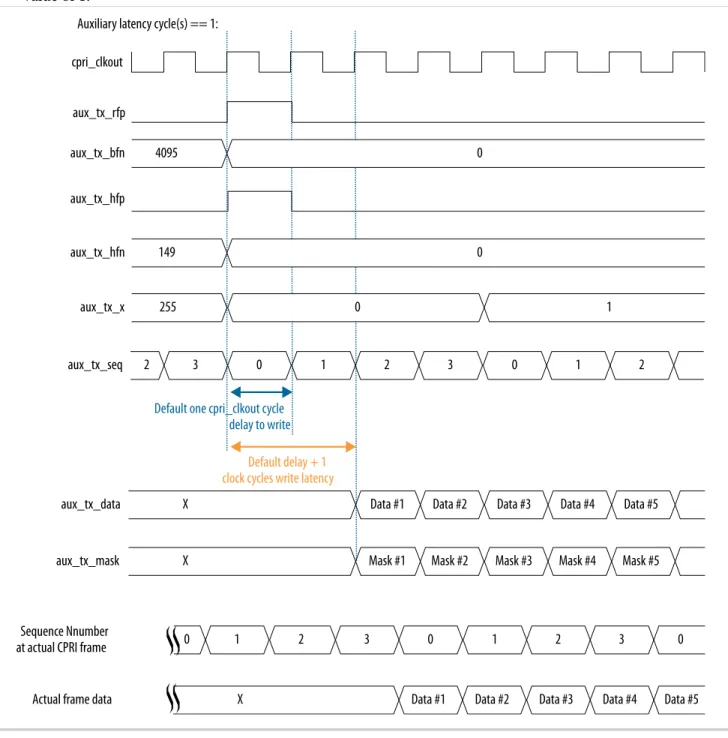
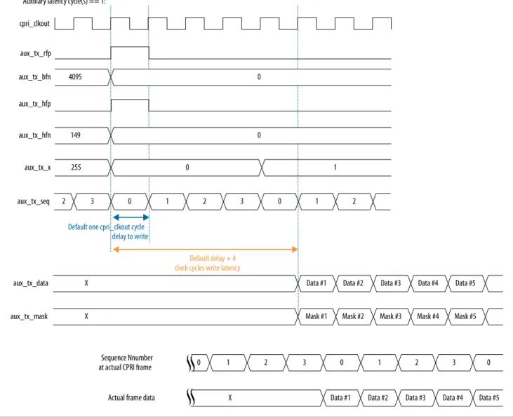
Auxiliary and direct interfaces write latency cycle(s)
0 to 9 0 Specifies the additional write latency on the AUX TX interface and other direct TX interfaces to the CPRI v6.0 IP core. The write latency is the number of cpri_clkout cycles from when the aux_tx_seq output signal has the value of 0 to
when user logic writes data to the AUX TX interface. For other direct interfaces, the IP core notifies user logic when it is ready for input and the user does not need to monitor the aux_tx_ seq signal.
When Auxiliary and direct interfaces write latency cycle(s) has the value of zero, the write latency on the direct TX interfaces is one cpri_ clkout cycle. When Auxiliary and direct
interfaces write latency cycle(s) has the value of N, the write latency is (1+N) cpri_clkout cycles.
Set this parameter to a value that provides user logic with sufficient advance notice of the position in the CPRI frame. The processing time that user logic requires after determining the current position in the CPRI frame is implementation specific.
This parameter is available if you turn on at least one direct interface in your CPRI v6.0 IP core variation.
Enable auxiliary
interface • On• Off
Off Turn on this parameter to include the AUX interface in your CPRI v6.0 IP core. The AUX interface provides full access to the raw CPRI frame.
Enable all control word access via management interface
• On • Off
Off Turn on this parameter to enable access to all control words in a hyperframe using the CPRI v6.0 CTRL_INDEX, TX_CTRL, and RX_CTRL registers.
Use this option with caution. During transmis‐ sion, this feature has higher priority than the MII, the GMII, the HDLC serial interface, the L1 control and status interface, and the generation of special symbols (K28.5, D16.2, /S/, /T/) , and can overwrite standard control words in the
hyperframe. Enable direct Z.130.0
alarm bits access interface
• On • Off
Off Turn on this parameter to include a dedicated L1 control and status interface to communicate the contents of the CPRI frame Z.130.0 word, which includes alarms and reset signals.
2-12 CPRI v6.0 IP Core Parameters UG-20008 UG-200082016.07.22
Parameter Range Default
Setting Parameter Description
Enable direct ctrl_axc
access interface • On• Off
Off Turn on this parameter to include a dedicated interface to access the Ctrl_AxC subchannels in the CPRI frame.
Enable direct vendor specific access interface
• On • Off
Off Turn on this parameter to include a dedicated interface to access the VS subchannels in the CPRI frame.
Enable direct real-time vendor specific interface
• On • Off
Off Turn on this parameter to include a dedicated interface to access the RTVS subchannel in the CPRI frame.
This parameter is available when you specify a CPRI line bit rate of 10137.6 Mbps.
Enable start-up sequence state machine
• On • Off
Off Turn on this parameter to include a start-up sequence state machine in the CPRI v6.0 IP core. If you turn off this parameter and also turn off Enable line bit rate auto-negotiation, Enable single-trip delay calibration, and in Arria 10 devices, the Enable ADME, transceiver capability, control and status registers access, the transceiver reconfiguration interface is not available.
This parameter is available if you set the value of Operation mode to TX/RX Duplex.
Enable protocol version and C&M channel setting auto-negotiation
• On • Off
Off Turn on this parameter to include a negotiator block that performs auto-negotiation of L1 inband protocol version (communicated in CPRI frame position Z.2.0) and L2 C&M rates
(communicated in CPRI frame positions Z.66.0 and Z.194.0).
This parameter is available when you turn on Enable start-up sequence state machine. Enable direct IQ
mapping interface • On• Off
Off Turn on this parameter to include a dedicated interface to access the raw I/Q data bytes in the CPRI frame.
L2 Features
Enable HDLC serial
interface • On• Off
Off Turn on this parameter to include a dedicated interface to communicate the contents of the slow C&M subchannels.
For full HDLC communication, you must connect a user-defined HDLC module to this interface.
UG-20008 UG-20008
2016.07.22 CPRI v6.0 IP Core Parameters 2-13
Getting Started with the CPRI v6.0 IP Core Altera Corporation
Parameter Range Default
Setting Parameter Description
Ethernet PCS
interface • NONE• MII
• GMII
NONE Specify whether to include an MII or GMII port to communicate with the fast C&M (Ethernet) CPRI subchannel. You can also specify that the IP core does not support either interface.
• An MII port complies with the IEEE 802.3 100BASE-X 100Mbps MII specification, • A GMII port complies with the IEEE 802.3
1000BASE-X 1Gbps GMII specification. For full Ethernet communication, you must connect a user-defined Ethernet MAC to this interface.
L2 Ethernet PCS Tx/ Rx FIFO depth
7, 8, 9, 10, 11 7 The value you specify for this parameter is log2 of the IP core Layer 2 Ethernet PCS Rx buffer depth and Tx buffer depth. The IP core supports a maximum Layer 2 Ethernet PCS buffer depth of 1024 for MII and 2048 for GMII.
This parameter is available when you include an MII or GMII port to communicate with the fast C&M (Ethernet) CPRI subchannel by selecting the value of MII or GMII for the Ethernet PCS interface parameter.
The new value of 11 is supported only for GMII. Debug Features
Enable L1 debug
interfaces • On• Off
Off Turn on this parameter to include dedicated transceiver status and L1 Rx status interfaces to support debug.
This parameter is not available if you set the value of Operation mode to TX Simplex.
Enable ADME, transceiver capability, control and status registers access
• On • Off
Off Turn on this parameter to support debugging through the Altera System Console and to expose transceiver registers. If you turn off this parameter and also turn off Enable line bit rate auto-negotiation, Enable start-up sequence state machine, and Enable single-trip delay calibra‐ tion, the Arria 10 transceiver reconfiguration interface is not available.
This parameter is available only for Arria 10 devices.
2-14 CPRI v6.0 IP Core Parameters UG-20008 UG-200082016.07.22
Parameter Range Default
Setting Parameter Description
Enable transceiver PMA serial forward loopback path
• On • Off
Off Turn on this parameter to enable transceiver PMA serial forward loopback. To turn on transceiver PMA serial forward loopback (Tx to Rx), you must also write the value of 2'b01 to the
loop_forward field of the LOOPBACK register at
offset 0x44.
This parameter is not available if you set the value of Operation mode to TX Simplex or to RX Simplex. Enable parallel forward loopback paths • On • Off
Off Turn on this parameter to enable other internal parallel forward loopback paths (Tx to Rx). To turn on internal parallel forward loopback, you must also write a non-zero value to the loop_ forward field of the LOOPBACK register at offset
0x44.
This parameter is not available if you set the value of Operation mode to TX Simplex or to RX Simplex. Enable parallel reversed loopback paths • On • Off
Off Turn on this parameter to enable internal parallel reverse loopback (Rx to Tx). To turn on reverse loopback, you must also write a non-zero value to the loop_reversed field of the LOOPBACK register
at offset 0x44, to specify the parts of the CPRI frame that are sent on the loopback path.
This parameter is not available if you set the value of Operation mode to TX Simplex or to RX Simplex.
UG-20008 UG-20008
2016.07.22 CPRI v6.0 IP Core Parameters 2-15
Getting Started with the CPRI v6.0 IP Core Altera Corporation
Table 2-4: CPRI v6.0 IP Core Advanced Feature Parameters
Describes the parameters for customizing the CPRI v6.0 IP core delay calibration features. These parameters appear on the Advanced tab in the CPRI v6.0 parameter editor.
Parameter Range Default
Setting Parameter Description
Enable single-trip
delay calibration • On• Off Off Turn on this parameter to specify that your CPRIv6.0 IP core supports single-trip delay calibration. If you turn on this parameter, your IP core implements single-trip delay calibration only if you connect it according to Adding and Connecting the Single-Trip Delay Calibration Blocks on page 2-22. Altera provides the required external blocks but you must connect them to the IP core in your design.
If you turn off this parameter and also turn off Enable line bit rate auto-negotiation, Enable start-up sequence state machine, and in Arria 10 devices, the Enable ADME, transceiver
capability, control and status registers access, the transceiver reconfiguration interface is not available.
This parameter is available only if you set the value of the Core clock source input parameter to External.
Enable round-trip
delay calibration • On• Off Off Turn on this parameter to to specify that yourCPRI v6.0 IP core supports round-trip delay calibration.
This parameter is available only if you set the value of the Synchronization mode parameter to Master. Round-trip delay calibration FIFO depth • 2 • 3 • 4
2 The value you specify for this parameter is log2 of the IP core RTD calibration buffer depth.The IP core supports a maximum RTD calibration buffer depth of 16.
The default depth of the buffer is 4, specified by the parameter default value of 2. For buffer depth
N, the Read pointer can move (N/2)-1 entries in either direction from its initial state.
Related Information
• LOOPBACK Register on page 5-14
• CPRI v6.0 IP Core Clocking Structure on page 3-3
2-16 CPRI v6.0 IP Core Parameters UG-20008 UG-200082016.07.22
Integrating Your IP Core in Your Design: Required External Blocks
You must connect your CPRI v6.0 IP core to some additional required design components. Your design can simulate and compile without some of these connections and logical blocks, but it will not function correctly in hardware unless all of them are present and connected in your design.
The CPRI v6.0 IP core requires that you define, instantiate, and connect the following additional software and hardware modules for all CPRI v6.0 IP core variations:
• An external PLL IP core to configure the transceiver TX PLL. Although the FPGA elements this IP core configures are physically part of the device transceiver, you must instantiate this IP core in software separately from the CPRI v6.0 IP core. In Arria 10 devices, this Altera requirement supports the configuration of multiple Altera IP cores using the same transceiver block in the device.
• One or more external reset controllers to coordinate the reset sequence for the CPRI v6.0 IP core in your design.
In addition, some IP core variations require additional modules to function correctly in hardware. • CPRI link slave modules require an off-chip clean-up PLL.
• Variations that target a 28-nm device (Arria V, Arria V GZ, Cyclone V, or Stratix V device family) require an external transceiver reconfiguration controller.
• Variations with the single-trip delay calibration feature require additional blocks that Altera provides but does not connect in your design.
UG-20008 UG-20008
2016.07.22 Integrating Your IP Core in Your Design: Required External Blocks 2-17
Getting Started with the CPRI v6.0 IP Core Altera Corporation
Figure 2-3: Required External Blocks
An example showing how you could connect required components to a single CPRI v6.0 IP core that targets an Arria 10 device.
Reset Controller
Reset Controller TX
PLL (Native PHY)Transmitter
Receiver (Native PHY) User-Defined Reference Clock xcvr_ext_pll_clk xcvr_tx_analogreset xcvr_tx_digitalreset xcvr_tx_cal_busy xcvr_rx_analogreset xcvr_rx_digitalreset xcvr_rx_is_lockedtodata xcvr_rx_cal_busy xcvr_cdr_refclk reset_tx_n reset_rx_n pll_locked CPRI v6.0 IP Core xcvr_reset_tx_ready xcvr_reset_rx_ready Related Information
Adding the Reset Controller on page 2-20
Adding the Transceiver TX PLL IP Core
The CPRI v6.0 IP core requires that you generate and connect a TX transceiver PLL IP core. The
transceiver PLL IP core configures the TX PLL in the transceiver on the device, but you must generate the transceiver PLL IP core separately from the CPRI v6.0 IP core in software. If you do not generate and connect the transceiver PLL IP core, the CPRI v6.0 IP core does not compile.
You can use the IP Catalog to generate the external PLL IP core that configures a TX PLL on the device. In the IP Catalog, select an Altera IP core that configures an appropriate PLL on your target device.
For your 28-nm design, you can select Altera PLL (FPLL) or Transceiver PLL v16.0 in the IP Catalog. In the parameter editor for the TX PLL IP core you select, you must set the PLL output frequency to the expected input frequency for the CPRI v6.0 IP core xcvr_ext_pll_clk input signal.
2-18 Adding the Transceiver TX PLL IP Core UG-20008 UG-200082016.07.22
For your Arria 10 design, you can select Arria 10 Transceiver ATX PLL, Arria 10 Transceiver CMU PLL, or Arria 10 FPLL in the IP Catalog. In the parameter editor for the TX PLL IP core you select, you must set the following parameter values:
• PLL output frequency to one half the per-lane data rate of the IP core variation, multiplied by the value of the Transmitter local clock division factor parameter of the CPRI v6.0 IP core. The
transceiver performs dual edge clocking, using both the rising and falling edges of the input clock from the PLL. Therefore, this PLL output frequency setting drives the transceiver with the correct clock for the CPRI v6.0 IP core line bit rate.
For example, if your CPRI v6.0 IP core variation has a CPRI line bit rate of 10.1376 Gbps and you set the Transmitter local clock division factor parameter to the value of 1, you must set the TX PLL PLL output frequency parameter to the value of 5068.8 MHz.
• PLL reference clock frequency to a frequency at which you can drive the TX PLL input reference clock. You must drive the external PLL reference clock input signal at the frequency you specify for this parameter.
For example, if your CPRI v6.0 IP core variation has a CPRI line bit rate of 10.1376 Gbps and you set the Transmitter local clock division factor parameter to the value of 1, you can set the PLL reference clock frequency to the value of 307.2 MHz.
Arria 10 devices and the Quartus Prime software support multiple options for configuring an Arria 10 TX PLL. Depending on the TX PLL IP core you select and the configuration options you prefer, you have a wide range of choices in parameterizing the external TX PLL for an Arria 10 variation.
You must connect the external TX PLL signals and the CPRI v6.0 IP core transceiver TX PLL interface signals according to the following rules.
Table 2-5: Required Connections Between Transceiver TX PLL and CPRI v6.0 IP Core
Connect the xcvr_ext_pll_clk input signal of the CPRI v6.0 IP core to the pll_clkout, tx_serial_clk, or outclk0 output signal of the external PLL IP core. Information about connecting the transceiver TX PLL to the
Reset Controller is available in Adding the Reset Controller on page 2-20.
CPRI v6.0 IP Core Signal TX PLL Signal
xcvr_ext_pll_clk (input)
Arria 10 CMU or ATX PLL: tx_serial_clk
Arria 10 FPLL: outclk0
28-nm device CMU or ATX PLL: pll_clkout
28-nm device FPLL: outclk0
If your CPRI v6.0 IP core is an RE slave, drive the input signal of the external PLL IP core with the output of the off-chip cleanup PLL.
User logic must provide the connections. Refer to the demonstration testbench for example working user logic including one correct method to instantiate and connect the external PLL to a single CPRI v6.0 IP core.
Related Information
• Interface to the External PLL on page 3-65
UG-20008 UG-20008
2016.07.22 Adding the Transceiver TX PLL IP Core 2-19
Getting Started with the CPRI v6.0 IP Core Altera Corporation
• Altera Transceiver PHY IP Core User Guide
Information about how to configure an external PLL for your Arria V, Arria V GZ, Cyclone V, or Stratix V design.
• Arria 10 Transceiver PHY User Guide
Information about how to configure an external PLL for your own Arria 10 design.
Adding the Reset Controller
The CPRI v6.0 IP core requires that you provide reset control logic to handle the required reset sequence for the IP core transceiver on the device. For a duplex CPRI v6.0 IP core, you must generate and connect two Altera Transceiver PHY Reset Controller IP cores to perform this function, one reset controller for the TX transceiver and one reset controller for the RX transceiver in the CPRI v6.0 IP core. If you do not implement the device-specific correct reset sequence, the IP core does not function correctly in hardware. You can use the IP Catalog to generate Altera Transceiver PHY Reset Controller IP cores for the device family that your CPRI v6.0 IP core targets.
Follow the instructions in the Altera Transceiver PHY IP Core User Guide or the Arria 10 Transceiver PHY User Guide. The CPRI v6.0 IP core configures the Native PHY IP core for the target device family. You must configure the reset controllers to coordinate reset of the CPRI v6.0 IP core including the Native PHY IP core, and the transceiver PLL IP core. In the case of Arria V, Arria V GZ, Cyclone V, and Stratix V variations, the reset controllers must also coordinate with the transceiver reconfiguration controller. To configure a TX reset controller, in the Altera Transceiver PHY Reset Controller parameter editor, you must set the following parameter values:
• Set Input clock frequency to a value in the range of 100–150 MHz. You must drive the CPRI v6.0 IP core reconfig_clk at the same frequency you specify for this parameter.
• Turn on Synchronize reset input. • Turn on Use fast reset for simulation. • Turn on Enable TX PLL reset control.
• Set pll_powerdown duration to the value of 10. • Turn on Enable TX channel reset control.
• Leave all other parameters turned off or for the parameters that do not turn on or off, at their default values.
To configure an RX reset controller, in the Altera Transceiver PHY Reset Controller parameter editor, you must set the following parameter values:
• Set Input clock frequency to a value in the range of 100–150 MHz. You must drive the CPRI v6.0 IP core reconfig_clk at the same frequency you specify for this parameter.
• Turn on Synchronize reset input. • Turn on Use fast reset for simulation. • Turn on Enable RX channel reset control.
• Leave all other parameters turned off or for the parameters that do not turn on or off, at their default values.
You must connect the external reset controller signals to the CPRI v6.0 IP core reset controller interface signals and transceiver TX PLL signals according to the following rules. Refer to Integrating Your IP Core in Your Design: Required External Blocks on page 2-17 for an illustration of the connections.
2-20 Adding the Reset Controller UG-20008 UG-200082016.07.22
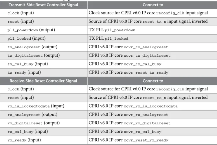
Table 2-6: Required Connections to and From Reset Controllers in CPRI v6.0 Design
Lists the required connections between the reset controllers and the CPRI v6.0 IP core and the transceiver TX PLL IP core. For information about connecting the transceiver TX PLL to the CPRI v6.0 IP core, refer to Adding the Transceiver TX PLL IP Core on page 2-18.
Transmit-Side Reset Controller Signal Connect to
clock (input) Clock source for CPRI v6.0 IP core reconfig_clk input signal
reset (input) Source of CPRI v6.0 IP core reset_tx_n input signal, inverted
pll_powerdown (output) TX PLL pll_powerdown
pll_locked (input) TX PLL pll_locked
tx_analogreset (output) CPRI v6.0 IP core xcvr_tx_analogreset
tx_digitalreset (output) CPRI v6.0 IP core xcvr_tx_digitalreset
tx_cal_busy (input) CPRI v6.0 IP core xcvr_tx_cal_busy
tx_ready (input) CPRI v6.0 IP core xcvr_reset_tx_ready
Receive-Side Reset Controller Signal Connect to
clock (input) Clock source for CPRI v6.0 IP core reconfig_clk input signal
reset (input) Source of CPRI v6.0 IP core reset_rx_n input signal, inverted
rx_is_lockedtodata (input) CPRI v6.0 IP core xcvr_rx_is_lockedtodata
rx_analogreset (output) CPRI v6.0 IP core xcvr_rx_analogreset
rx_digitalreset (output) CPRI v6.0 IP core xcvr_rx_digitalreset
rx_cal_busy (input) CPRI v6.0 IP core xcvr_rx_cal_busy
rx_ready (input) CPRI v6.0 IP core xcvr_reset_rx_ready
User logic must provide the connections. Refer to the demonstration testbench for example working user logic including one correct method to instantiate and connect the external reset controllers.
Related Information
• Interface to the External Reset Controller on page 3-64
• Integrating Your IP Core in Your Design: Required External Blocks on page 2-17
Figure illustrates the required connections.
• Altera Transceiver PHY IP Core User Guide
Information about how to configure and connect the Altera Transceiver PHY Reset Controller for your Arria V, Arria V GZ, Cyclone V, or Stratix V design.
• Arria 10 Transceiver PHY User Guide
Information about how to configure and connect the Altera Transceiver PHY Reset Controller for your Arria 10 design.
Adding the Transceiver Reconfiguration Controller
CPRI v6.0 IP cores that target Arria V, Arria V GZ, Cyclone V, and Stratix V devices require an external reconfiguration controller to compile and to function correctly in hardware. CPRI v6.0 IP cores that target
UG-20008 UG-20008
2016.07.22 Adding the Transceiver Reconfiguration Controller 2-21
Getting Started with the CPRI v6.0 IP Core Altera Corporation
Arria 10 devices include a transceiver reconfiguration controller block and do not require an external reconfiguration controller.
You can use the IP Catalog to generate the Altera Transceiver Reconfiguration Controller IP core. When you configure the Altera Transceiver Reconfiguration Controller, you must specify the number of reconfiguration interfaces. The number of reconfiguration interfaces required for the CPRI v6.0 IP core depends on the CPRI v6.0 IP core configuration and your design.For example, you can configure your reconfiguration controller with additional interfaces if your design connects with multiple transceiver IP cores. You can leave other options at the default settings or modify them for your preference. Refer to the
Altera Transceiver PHY User Guide.
You should connect the reconfig_to_xcvr and reconfig_from_xcvr ports of the CPRI v6.0 IP core to
the corresponding ports of the reconfiguration controller.
You must drive the CPRI v6.0 IP core reconfig_clk input port and the Altera Transceiver Reconfigura‐
tion Controller mgmt_clk_clk input port from the same clock source. Drive both ports at a clock
frequency in the range of 100–150MHz.
Related Information
• Arria V, Arria V GZ, Cyclone V, and Stratix V Transceiver Reconfiguration Interface on page 3-62
• Altera Transceiver PHY IP Core User Guide
For more information about the Altera Transceiver Reconfiguration Controller.
Adding the Off-Chip Clean-Up PLL
If your CPRI v6.0 IP core is an RE slave, you must connect it to an off-chip clean-up PLL to clean up any jitter that occurs in the CDR output clock, before sending it to the reference clock input of the external TX PLL.
The clean-up PLL performs the clock synchronization necessary to address the CPRI v6.0 Specification requirements R-17, R-18, and R-18A, which address jitter and frequency accuracy in the RE core clock for radio transmisstion.
Drive the clean-up PLL with the CPRI v6.0 IP core xcvr_recovered_clk output clock, and connect the
cleaned up output to the external TX PLL input reference clock port. In the internal clocking mode, in 8.11008 Gbps and 10.1376 Gbps IP core variations, you should connect the cleaned up output to the
cpri_coreclk input clock port as well. In the external clocking mode, you can optionally connect the
cleaned up output to the cpri_coreclk input clock port.
Related Information
CPRI v6.0 IP Core Clocking Structure on page 3-3
Adding and Connecting the Single-Trip Delay Calibration Blocks
If you turn on Enable single-trip delay calibration in the CPRI v6.0 parameter editor, and Synchroniza‐ tion mode is set to Slave, the CPRI v6.0 IP core requires that you connect the IOPLL (pll_core block)
and the Dynamic Phase Control Unit (DPCU) (pll_dpcu block). You must generate a device core PLL to
create the IOPLL. Altera provides the DPCU block with the CPRI v6.0 IP core, but you must connect it, and the IOPLL, in your design. A single IOPLL block and a single DPCU block can connect to multiple CPRI v6.0 IP cores.
2-22 Adding the Off-Chip Clean-Up PLL UG-20008 UG-200082016.07.22