Final Report
Town of Holden, Massachusetts
Water Distribution System Master Plan
May 2006
Contents
Executive Summary
Section 1 - Introduction
1.1 Water System History ...1-1 1.2 Purpose of Project...1-4 1.3 Project Scope...1-4 1.4 Report Organization...1-5
Section 2 - Description of Existing System
2.1 General ...2-1 2.2 Supply Sources...2-3 2.3 Distribution System Interconnections ...2-5 2.4 Distribution System Storage ...2-6 2.5 Distribution System Booster Stations ...2-8 2.6 Distribution System Piping ...2-9
Section 3 - Population and Demand Projections
3.1 General ...3-1 3.2 Past Population Trends and Future Population Projections ...3-1 3.3 Water Consumption Trends and Projections ...3-5 3.3.1 Water Consumption Definitions ...3-5 3.3.2 Historic Water Consumption...3-6 3.3.3 Water Consumption Projections ...3-7 3.3.4 Residential per Capita Consumption ...3-7
Section 4 - Fire Flow Requirements
4.1 General ...4-1 4.2 ISO Background...4-1 4.3 ISO Required Fire Flow Methodology...4-1 4.4 ISO Results...4-2
Section 5 - Distribution System Model
5.1 General ...5-1 5.2 Hydraulic Model...5-1 5.3 Development of System Schematic ...5-2 5.4 Assigning Demands ...5-2 5.5 Pipe Friction Factors...5-3 5.6 Model Calibration...5-4 5.6.1 Hydrant Flow Tests...5-4 5.6.2 C-Value Tests ...5-6
A
i5.6.3 Calibration Methods ...5-7 5.6.4 Calibration Results ...5-7 5.7 Model Validation...5-8
Section 6 - Distribution System Evaluation
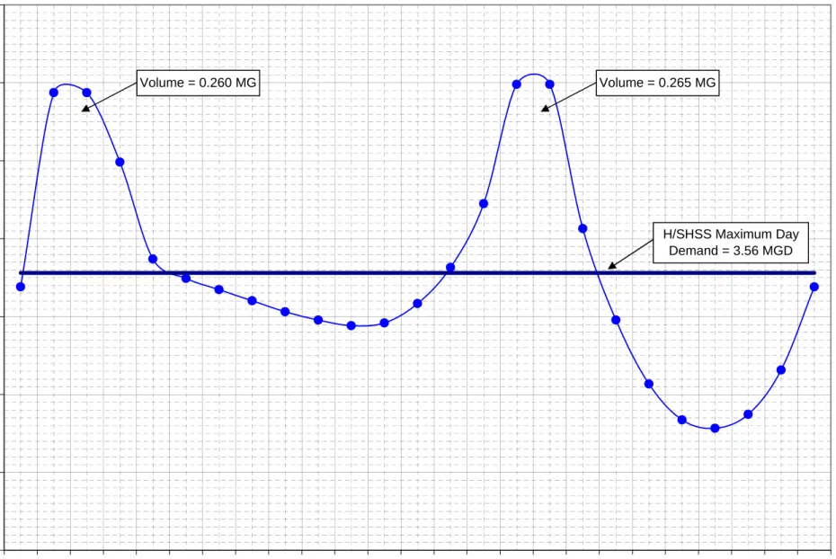
6.1 General ...6-1 6.2 System Hydraulic Analysis Criteria ...6-1 6.2.1 Minimum System Pressures ...6-1 6.2.2 Maximum Velocities and Head Loss...6-1 6.2.3 Fire Flow Requirements ...6-2 6.3 Distribution System Storage Analysis ...6-3 6.3.1 Active Storage Requirements ...6-3 6.3.2 Analysis of Existing Storage ...6-4 6.3.3 Available Emergency Storage...6-10 6.3.4 Distribution System Storage Analysis Results ...6-10 6.4 Distribution System Reliability Analysis ...6-10
6.4.1 Mechanical Failure Analysis...6-10 6.4.2 Major Water Main Failure Analysis...6-12 6.4.3 Power Failure Analysis...6-13 6.5 Piping System Analysis ...6-16 6.5.1 Maximum Day plus Fire Flow Evaluation...6-16 6.5.2 Peak Hour Evaluation...6-17 6.5.3 Piping System Deficiencies ...6-18 6.5.4 General Piping System Deficiencies ...6-19 6.6 Super High Service System Analysis...6-20 6.6.1 Chapin Road Tank Super High System ...6-20 6.6.2 Fox Hill Development Super High System...6-21 6.6.3 Morningside Development Super High System ...6-22 6.7 Additional System Analysis...6-23
6.7.1 Salisbury Street Interconnection Booster Station
Operating Parameters Evaluation...6-23 6.7.2 Chapin Road Tank Operation Evaluation ...6-23 6.7.3 Rutland Emergency Water Supply Interconnection Evaluation ...6-24 6.7.4 Water Storage Tank Inspection Evaluation ...6-25 6.8 Summary of Existing System Deficiencies...6-25
Section 7 - Recommended Improvement Program
7.1 General ...7-1 7.2 Geographic Information System (GIS) ...7-1 7.3 Annual Maintenance Program Recommendation ...7-3 7.3.1 Valve Maintenance Program ...7-3 7.3.2 Hydrant Maintenance Program ...7-4
Table of Contents Holden Water Distribution System Master Plan
7.3.3 Unidirectional Flushing Program ...7-5 7.3.4 Storage Tank Inspection Program...7-5 7.3.5 Wellfield Redevelopment Program ...7-6 7.3.6 Water Conservation Program...7-6 7.3.7 Unaccounted-for Water Reduction Program...7-6 7.4 Storage and Pump Station Capital Improvements ...7-8 7.4.1 Water Storage Tank Improvements...7-9 7.4.2 Water Storage Tank Operation Improvements...7-9 7.4.3 Pumping Station Improvements ...7-9 7.4.4 Supply Facility Improvement...7-10 7.5 Piping System Capital Improvements...7-11 7.5.1 General Pipe Rehabilitation ...7-11 7.5.2 Implementation of Pipe Rehabilitation Program...7-13 7.6 Prioritized Capital Improvement List...7-14
Appendices
Appendix A Water Distribution System Map Appendix B Water Main Rehabilitation Map
A
iiiFigure 2-1 – Water System Isometric Plan...2-2 Figure 3-1 – Population Trends and Projections ...3-4 Figure 5-1 – Diurnal Demand Patterns...5-11 Figure 5-2 – Average Day Model Validation ...5-12 Figure 5-3 – Maximum Day Model Validation...5-13 Figure 5-4 – Minimum Day Model Validation ...5-14 Figure 6-1 – Low Service System 2030 Hourly Demand on Maximum Day...6-6 Figure 6-2 – High/Super High Service System 2030 Hourly
Tables
Table E-1 – Summary of Annual Maintenance Programs... ES-7 Table E-2 – Summary of Storage and Pump Station Capital
Improvement Program ... ES-8 Table E-3 – Summary of Piping System Capital Improvement Program... ES-9 Table E-4 – Prioritized Capital Improvement List ... ES-10 Table 2-1 – Groundwater Supply Facilities...2-4 Table 2-2 – Water Storage Facilities...2-7 Table 3-1 – USCB Population Census ...3-1 Table 3-2 – Town Clerk Population Census...3-2 Table 3-3 – Historical Water Consumption...3-8 Table 3-4 – Projected Water Consumption...3-9 Table 4-1 – ISO Fire Flow Requirements for 1- or 2- Family Dwellings ...4-2 Table 4-2 – 1991 ISO Fire Flow Test Data Summary...4-3 Table 4-3 – 2003 ISO Fire Flow Test Data Summary...4-4 Table 5-1 – Hydrant Flow Test Data Summary ...5-5 Table 5-2 – C-Value Test Data Summary...5-7 Table 5-3 – Calibration Results Summary ...5-8 Table 5-4 – Diurnal Demand Pattern Multipliers...5-10 Table 6-1 – 2003 ISO Fire Flow Test Data Summary...6-2 Table 6-2 – Active Storage Volume Analysis...6-5 Table 6-3 – Water Facility Capacities ...6-11 Table 6-4 – Mechanical Failure Analysis ...6-12 Table 6-5 – Water Main Break Analysis...6-14 Table 6-6 – Power Failure Analysis...6-15 Table 6-7 – ISO Required Fire Flow Duration ...6-17 Table 7-1 - Summary of Annual Maintenance Programs...7-8 Table 7-2 – Summary of Storage and Pump Station
Capital Improvement Program ...7-10 Table 7-3 – Unit Costs for Piping System Capital Improvement Program...7-11 Table 7-4 – Summary of Piping System Capital Improvement Program ...7-12 Table 7-5 – Prioritized Capital Improvement List...7-14
A
vIntroduction
The Town of Holden has recently completed an extensive infrastructure improvement program to its water distribution system. These improvements were necessary to achieve compliance with the federal mandated Safe Drinking Water Act (SDWA) and to ensure adequate water supply capacity for Holden well into the future. The water distribution system study has proceeded in parallel with these improvements. In fact, the study has provided the technical design basis for many of the infrastructure improvements and facility modifications implemented.
In general, the overall goals and objectives of this water distribution system master plan have been to:
1. Provide the Town of Holden with an up-to-date map of its water distribution system.
2. Develop a calibrated hydraulic model of the water distribution system for identifying system deficiencies and for analyzing the impact of changes to the system.
3. Evaluate Holden’s distribution system over a 30-year planning period and develop a prioritized list of improvements needed to provide the town with safe and reliable water service.
Recommended improvements to the system are aimed at correcting existing system deficiencies, as well as potential future deficiencies. The design year has been
estimated as 2030 and water demands have been projected over this planning period.
Project Scope
The following major tasks have comprised the scope of this project:
Data Collection
Water Quality Assessment Computer Model Development Field Testing
Distribution System Piping Analysis Distribution System Storage Analysis Distribution System Reliability Analysis Development of Recommended Improvements
Recommendation of an Annual Maintenance Program
Cost Estimating of Recommended Improvements and Programs Report Preparation
Executive Summary
Existing Distribution System
The Town of Holden’s water distribution system is comprised of four groundwater wellfields, two interconnections with the City of Worcester, one emergency surface water connection, four water storage tanks, and approximately 105 miles of water mains of various types, sizes and ages. The distribution system is also divided into two major pressure zones to serve the range of elevations of the water service areas. The location of all the water system facilities are shown on the Water Distribution System Map, appended to this report.
All of the town’s water is supplied from the following facilities:
Mason Road Wellfield (Low Service System) Mill Street Wellfield (Low Service System) Quinapoxet Wellfield (Low Service System) Spring Street Well (High Service System)
Brattle Street interconnection with Worcester (High Service System) Salisbury Street interconnection with Worcester (High Service System) Muschopauge Pond (High Service System - Emergency Supply Only)
All of the Town’s water supply facilities are treated with sodium fluoride for fluoridation and all of the Town’s groundwater supply facilities are treated with potassium hydroxide for corrosion control. The Spring Street Well can also be treated with sodium hypochlorite for disinfection, if required. Similarly, the Quinapoxet and Mill Street Wellfield treatment facility has room to install sodium hypochlorite for disinfection, if required in the future.
The town’s water distribution system includes the following storage facilities:
Highland Street Reservoir (Low Service System) Avery Heights Standpipe (High Service System) Jefferson Reservoir (High Service System)
Chapin Road Reservoir (Super High Service System)
The Highland Street Reservoir is a reinforced concrete tank. The Avery Heights Standpipe, Jefferson Reservoir, and Chapin Road Reservoir are all welded steel water storage tanks.
Holden’s distribution system also consists of approximately 105 miles of water mains, with approximately 25 miles of cast iron water mains (4 miles of which have been cleaned and cement lined), 45 miles of asbestos cement water mains and 35 miles of cement lined ductile iron water mains.
A
ES-2Water Consumption Projections
To determine the water system improvements required to adequately satisfy Holden’s future needs, population census and water consumption data from the past 15 years were reviewed. Based on the population trend, CDM projected the average day, maximum day and peak hour water demands for the town. These projections resulted in the following water consumption estimates for the year 2030:
Average Day Demand – 1.95 MGD Maximum Day Demand – 3.90 MGD Peak Hour Demand – 6.83 MGD
Water Distribution System Model Development
To evaluate Holden’s water distribution system under estimated future 2030
conditions, a computer model of the distribution system was developed. The software used to simulate the water distribution system was WaterGEMS® Version 3.0
developed and distributed by Haestad Method, Inc. of Waterbury, Connecticut. The data used to develop the model was provided by the Town and was based primarily on the existing water distribution system pipe schematic map. CDM conducted hydrant flow tests and C-value tests to calibrate the model to field conditions. The calibrated model was then verified by comparing model outputs to the Supervisory Control and Data Acquisition (SCADA) system data. The calibrated and validated model was then used to identify water system deficiencies.
Distribution System Evaluation Criteria
CDM evaluated Holden’s piping, pumping and storage facilities to determine the adequacy of the existing water distribution system to meet future water demand conditions and provide fire protection. The water distribution system, including the recent improvements, was evaluated using the calibrated model developed for the project. The following analysis criteria were established.
System Hydraulic Analysis Criteria
The water system facilities (i.e., piping, pumping and storage facilities) were
evaluated to determine the system’s ability to meet minimum pressure requirements under the following demand conditions for the target year of 2030:
Fire flow requirements during maximum day demand Peak hour during maximum day demand
According to the Massachusetts Department of Environmental Protection (MassDEP) 2001 Guidelines and Polices for Public Water Systems, the criteria for water main design is: “The system shall be designed to maintain a minimum pressure of 20 psi at ground level at all points in the distribution system under all operating conditions.” This standard helps to avoid potential cross-connections and negative pressures
Executive Summary
(vacuum) that could occur at service connections (at high elevations) during fire flows or other significant demand events.
For this study, the desired minimum pressure during the peak hour demand period was 35 psi at ground elevation in all areas of the Town served by the water system. During a maximum day demand with a coincidental fire flow, the desired minimum pressure of 20 psi should be maintained throughout the system.
In addition, according, to the American Water Works Association (AWWA) Manual of Water Supply Practices, “Computer Modeling of Water Distribution System” (AWWA M32, Second Edition, 2005), pipes are considered potentially deficient or limiting if they are predicted to have any of the following conditions:
Velocities greater than 5 feet per second;
Head losses greater than 6 feet per 1,000 feet in pipes with diameters less than
16 inches;
Head losses greater than 2 feet per 1,000 feet in pipes with diameters 16-inch and
greater.
These limits were used as a general indicator of potential problems. The ultimate test of the adequacy of a water main is the pressure that is provided at the delivery point in order to meet the required Insurance Services Office (ISO) fire flow rate.
Distribution System Storage Analysis Criteria
Adequate storage is defined as the ability of the system to provide the storage volume required as summarized below:
Equalization Storage: The total volume required to meet hourly demand, which
exceeds the maximum day demand.
Fire Protection Storage: The total volume of water required to provide fire
protection.
Emergency Storage: The volume of storage allocated in case of a power failure,
pipeline break, or equipment malfunction.
Distribution System Reliability Analysis Criteria
Adequate system reliability is defined as the ability of the system to supply maximum day demand under various emergency conditions. Emergency conditions include equipment malfunctions, pipeline break, or power failure.
Distribution System Evaluation Results
Based on the analyses conducted on the existing storage, pumping and piping facilities, which include all the recent improvements, the following conclusions were
A
ES-4demands for 2030:
There is adequate active storage volume in the system to meet projected future
demand conditions. To improve water level operation within the Chapin Road Tank, CDM recommends an upgrade to the existing PRV located within the Chapin Road Booster Station to an electrically controlled valve, similar to the Brattle Street Interconnection Valve, and abandonment of the Chapin Road PRV located within the below ground vault. CDM also recommends that the Town perform a structural analysis of the Highland Street Storage Tank and inspect and rehabilitate steel tank coating systems of the Chapin Road Tank and Avery
Heights Tank.
There are adequate pumping facilities to supply all zones to meet projected future
demands. The pumping facilities also have sufficient pumping redundancy and the system has adequate emergency storage volume to supply projected
maximum day demand under various emergency conditions in all service zones, with the exception of the Morningside Development super high system and Fox Hill Development super high system. For the Morningside Development super high system, CDM recommends that the Town install a second lead pump and VFD to provide adequate redundancy at the Morgan Circle Booster Station. For the Fox Hill Development super high system, CDM recommends that the Town install a permanent fire pump at the Sycamore Drive Booster Station to provide adequate fire protection. Until a permanent fire pump is installed at the Sycamore Drive Booster Station, CDM recommends that the Town develop a fire protection plan with the Fire Department and install two hydrants located near the Chapin Road Tank access road to allow the fire department to pump water from the Chapin Road Tank super high system into the Fox Hill Development super high system. CDM also recommends that the Town purchase a portable standby generator for the Brattle Street Valve Vault in order to operate the facility fully during an emergency power failure.
In general, Holden’s water distribution system is considered hydraulically
well-connected. The water distribution system, inclusive of the recent water system improvements, can meet projected future demands while maintaining a residual of 35 psi or greater throughout the system, with the exception of the very limited areas immediately surrounding the water storage tanks. As predicted by the computer model, the water distribution system is also able to provide the required fire flows under projected future demands at all ISO test locations, with the
exception of Boyden Street at Woodland Road.
Replacing the 6-inch unlined cast iron water main on Boyden Street and the 6-inch
unlined cast iron water main on Woodland Road with new 8-inch cement lined ductile iron water mains would address the one deficient ISO fire flow area.
Overall, by replacing or rehabilitating the other hydraulically deficient water
Executive Summary
water quality complaints associated with system disruptions and dirty water. In addition, the Town should work to remove all small diameter water mains, hydraulic bottlenecks in the system, and replace aging and problematic asbestos cement water mains whenever possible.
Recommendations for capital improvements to the distribution system are aimed at correcting the remaining water distribution system inadequacies detailed above and discussed below.
Recommended Improvement Program
The overall objective of these improvements is to provide adequate system flow capacity, meet pressure criteria, and improve reliability and water quality. The recommended improvements program is arranged in four categories:
Geographic Information System (GIS) Implementation: – GIS implementation
for the Town will provide the Water Department with more accurate water system maps and help manage the water system maintenance program.
Annual Maintenance Program Recommendations: The Annual Maintenance
Program Recommendations address such times as storage facility inspection programs and hydrant and valve maintenance programs. These programs should be initiated as soon as possible and extend over the long-term since proper
operation and maintenance of these facilities can result in significant
improvements in system hydraulics and water quality. In addition, many of these programs are now required in order to maintain compliance with the Town’s Water Management Act (WMA) permit.
Storage and Pumping Station Capital Improvements: Storage and Pumping
Station Capital Improvements address storage and pumping station deficiencies. Storage and Pumping Station Capital Improvements will improve available storage and distribution system reliability and are therefore the highest priority improvements.
Piping System Capital Improvements: Piping System Capital Improvements
address piping system deficiencies identified in the hydraulic analysis. Piping System Capital Improvements will improve overall piping network reliability and water quality, and can be implemented over the long-term (see appended Water Main Rehabilitation Map).
Table E-1 provides an estimated annual allowance for the Annual Maintenance Program. Table E-2 provides estimated construction costs for Storage and Pumping Station Capital Improvements. Table E-3 provides estimated construction costs for Piping System Capital Improvements.
The estimated annual allowances and estimated construction project cost in the tables are based on current construction and engineering costs as of April 2006 and are referenced to an Engineering News Record (ENR) Construction Cost Index of 7695.
A
ES-6an allowance of 45 percent for engineering and contingencies.
For a more detailed discussion of each of these recommendations, please see Section 7 of this report.
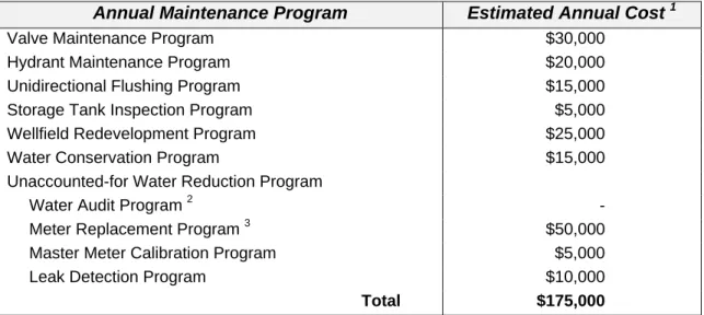
Table E-1
Summary of Annual Maintenance Programs
Annual Maintenance Program Estimated Annual Cost 1 Valve Maintenance Program $30,000
Hydrant Maintenance Program $20,000 Unidirectional Flushing Program $15,000 Storage Tank Inspection Program $5,000 Wellfield Redevelopment Program $25,000 Water Conservation Program $15,000 Unaccounted-for Water Reduction Program
Water Audit Program 2 - Meter Replacement Program 3 $50,000 Master Meter Calibration Program $5,000 Leak Detection Program $10,000
Total $175,000
Notes: 1. Estimated annual cost only covers the cost of materials, water purchase from Worcester and/or subcontractors including contingency. Estimated annual cost does not include cost of town forces. All costs are in year 2006 dollars (ENR April 2006 = 7695).
2. No cost shown as work assumed to be performed by Town.
Executive Summary
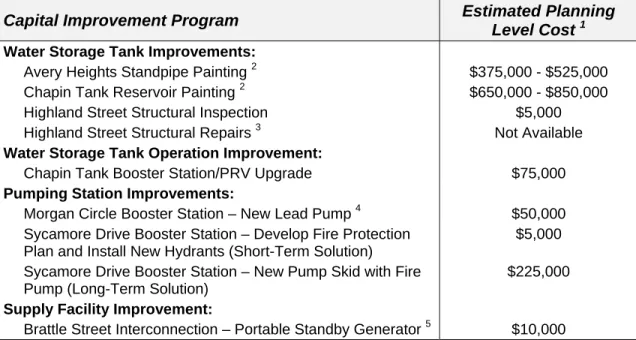
Table E-2
Summary of Storage and Pump Station Capital Improvement Program
Capital Improvement Program Estimated Planning
Level Cost 1
Water Storage Tank Improvements:
Avery Heights Standpipe Painting 2 $375,000 - $525,000 Chapin Tank Reservoir Painting 2 $650,000 - $850,000 Highland Street Structural Inspection $5,000 Highland Street Structural Repairs 3 Not Available
Water Storage Tank Operation Improvement:
Chapin Tank Booster Station/PRV Upgrade $75,000
Pumping Station Improvements:
Morgan Circle Booster Station – New Lead Pump 4 $50,000 Sycamore Drive Booster Station – Develop Fire Protection
Plan and Install New Hydrants (Short-Term Solution)
$5,000
Sycamore Drive Booster Station – New Pump Skid with Fire Pump
$225,000
Supply Facility Improvement:
Brattle Street Interconnection – Portable Standby Generator 5 $10,000 Note: 1. The estimated planning level costs for water storage tank operation, pump station and supply facility
improvements include construction, engineering and contingency. All costs are in year 2006 dollars (ENR April 2006 = 7695).
2. The tank painting costs will depend on the type of exterior surface preparation and exterior containment required. Cost does not include additional water purchase when tank(s) are off-line, if required. 3. No planning level cost can be provided until structural inspection complete.
4. The estimated planning level cost for the Morgan Circle Booster Station assumes the Town will procure the services of a factory authorized service provider for SyncroFlo (formally Liquid-trol) pump systems without the need for formal bid documents.
5. The estimated planning level cost for the Brattle Street Interconnection portable standby generator assumes the Town will purchase the portable standby generator and transfer switch directly for installation by the Town’s electrician.
A
ES-8Table E-3
Summary of Piping System Capital Improvement Program
Location 1 From To Existing Pipe
Diameter (in.) Approx. Length (ft) Replacement Pipe Diameter (in.) Cleaning & Cement Lining Estimated Planning Level Cost 2
Mayflower Cir. Colonial Dr. Colonial Dr. 6 1,000 8 $250,000
Boyden St. Main St. Main St. 6 1,000 8 $250,000
Woodland Rd. Boyden St. Highland St. 6 2,000 8 $500,000 Shrewsbury St. Main St. Brattle St. 10, 8 2,500/3,000 X $850,000 Shrewsbury St. Brattle St. West Boylston
Town Line 6 5,000 8 $1,250,000
Holden St. Shrewsbury St. Worcester
Town Line 6 6,000 8 $1,500,000
South Main St. Shrewsbury St. Newell Rd. 6 6,400 8 $1,600,000 Main St. Reservoir St. Shrewsbury St. 10 8,500 X $1,450,000
Bailey Rd. Main St. Existing 8” 6 3,000 8 $750,000
Salisbury St. Main St. Existing 12” 8 3,000 12 $900,000 Reservoir St. Main St. Existing 12” 6 1,500 12 $450,000
Doyle Rd. Brattle St. Worcester Town Line 6 3,000 8 $750,000
Chapel St. Shrewsbury St. Existing 12” 6 3,000 12 $900,000
Wachusett St. Shrewsbury St. End 6 1,500 8 $375,000
Lincoln Ave. Chapel St. End 6 1,500 8 $375,000
Highland St. Main St. Union St. 10, 8, 6 700/300/3,000 X $600,000
Total $12,750,000
Note: 1. Presented in order of high to low priority
2. Estimated planning level costs include construction, engineering and contingency. All costs are in year 2006 dollars (ENR April 2006 = 7695). No allowance for legal fees, land taking or easements.
Executive Summary
Prioritized Capital Improvement List
The following is a recommended prioritized list of improvement projects for implementation.
Table E-4
Prioritized Capital Improvement List
Capital Improvement Project Estimated Planning
Level Cost 1
Highest Priority Improvements (within 5 years)
Chapin Tank Reservoir Painting 2 $650,000 - $850,000 Highland Street Structural Inspection $5,000 Morgan Circle Booster Station – New Lead Pump 3 $50,000 Sycamore Drive Booster Station – Develop Fire Protection
Plan and Install New Hydrants (Short-Term Solution) $5,000 Chapin Tank Booster Station/PRV Upgrade $75,000 Brattle Street Interconnection – Portable Standby Generator 4 $10,000 Mayflower Circle Water Main Replacement $250,000
High Priority Improvements (within 10 years)
Avery Heights Standpipe Painting 2 $375,000 - $525,000 Boyden Street Water Main Replacement $250,000 Woodland Road Water Main Replacement $500,000 Shrewsbury Street Water Main Cleaning and Lining $850,000 Shrewsbury Street Water Main Replacement $1,250,000 Holden Street Water Main Replacement $1,500,000 South Main Street Water Main Replacement $1,600,000
Priority Improvements (within 20 years)
Main Street Water Main Cleaning and Lining $1,450,000 Bailey Road Water Main Replacement $750,000 Salisbury Street Water Main Replacement $900,000 Reservoir Water Main Replacement $450,000 Doyle Road Water Main Replacement $750,000 Chapel Street Water Main Replacement $900,000 Wachusett Street Water Main Replacement $375,000 Lincoln Ave Water Main Replacement $375,000 Highland Street Water Main Cleaning and Lining $600,000
Improvements with No Timeframe
Highland Street Structural Repairs 5 Not Available Sycamore Drive Booster Station – New Pump Skid with Fire
Pump (Long-Term Solution) $225,000
Note: 1. The estimated planning level costs for water storage tank operation, pump station, supply facility and piping system improvements include construction, engineering and contingency. All costs are in year 2006 dollars (ENR April 2006 = 7695). No allowance for legal fees, land taking or easements.
2. The tank painting costs will depend on the type of exterior surface preparation and exterior containment required. Cost does not include additional water purchase when tank(s) are off-line, if required.
3. The estimated planning level cost for the Morgan Circle Booster Station assumes the Town will procure the services of a factory authorized service provider for SyncroFlo (formally Liquid-trol) pump systems without the need for formal bid documents.
4. The estimated planning level cost for the Brattle Street Interconnection portable standby generator assumes the Town will purchase the portable standby generator and transfer switch directly for installation by the Town’s electrician.
5. No planning level cost can be provided until structural inspection complete.
A
ES-10Introduction
1.1 Water
System
History
Holden’s municipal water supply system began when the Town acquired the rights to construct a water supply under the provisions of the Acts of 1896, Chapter 180. This act provided the Town of Holden with the right to take water from Muschopauge Pond in Rutland by purchase or otherwise. In 1904, the Town accepted the provisions of the Act and in 1905 begin installing large diameter cast iron water mains from Muschopauge Pond into Holden Center.
Until the 1950s, Muschopauge Pond was the sole source of water for both Holden and Rutland. The serious depletion of Muschopauge Pond during dry years led the Town of Holden to have the engineering firm of Metcalf and Eddy study the existing supply and distribution system in 1949. The first 1950 Metcalf and Eddy report recommended chemical treatment of Muschopauge Pond water to control corrosion, taste and odor problems, while the second 1950 report recommended the exploration of Quinapoxet River Valley and other areas to develop groundwater supply sources. Based on these recommendations, Whitman and Howard Engineers designed the Muschopauge Pond Chemical Feed Building (constructed in 1952) and the Spring Street Well Station (constructed in 1955).
In 1953, the Town of Holden contracted Whitman and Howard to determine the storage requirements for critical conditions in Holden Center and Chaffinville. As a result of the investigation, the Town constructed the Avery Heights Standpipe, the Chaffin Elevated Tank, and the Adams Road Booster Station.
Once again in 1957, severe drought conditions caused the water level within Muschopauge Pond to become dangerously low. This led the Town to engage Whitman and Howard to further study groundwater supply sources. Their report recommended the construction of the Quinapoxet Wellfield (built in 1959). The report also recommended the construction of an intermediate reservoir and booster pump to avoid very high system pressures near the Quinapoxet Wellfield. As a result, the Highland Street Concrete Storage Tank was built along with the Highland Street Booster Station to boost water to the normal pressure of the system in Holden Center. In 1965, the Town of Holden hired Camp Dresser and McKee Inc. (CDM) to examine the adequacy of the supply sources, investigate possible supplemental sources of water and make cost comparisons of alternatives to develop a long-term water supply plan. The study included an extensive groundwater investigation in previously unexplored parts of town as well as consideration of constructing a dam and reservoir on Trout Brook, purchase of additional water from the Metropolitan District
Commission (MDC) or purchase of water from the City of Worcester. The report recommended the construction of a wellfield and pumping station at the Mill Street
Section 1 Introduction
site (constructed in 1967) and a new 12-inch water main and meter vault in Brattle Street in order to purchase water from Worcester (constructed in 1971).
In 1971, CDM performed a comprehensive engineering investigation of the Town’s water distribution system. The study included the appraisal of existing distribution mains and storage facilities and concluded with recommendations to improve the present system and enable expansion to meet anticipated demands. The investigation discovered deficient water storage in the Chaffinville area and poor water
transmission capacity from Holden Center to supply the Chaffinville section of Town. The report recommended the construction of a new water storage tank in south Holden off Chapin Road. The report also recommended the construction of new water mains to increase transmission capacity from Holden Center to southeast Holden. One water main would travel from Holden Center to the Chaffinville area via the Unionville section of Town. The other water main would connect the proposed tank to southeastern Holden via Newell Road and cross-country to Brattle Street. With these two new water mains installed in the early 1970s, the Town was able to significantly increase the transmission capacity into southeast Holden, which rendered the need to boost water into southwest Holden, via the Adams Street Booster Station, obsolete.
In 1974, CDM was contracted to prepare plans and specifications for the Mason Road Wellfield. This site was identified as a potential site in CDM’s “Report on Additional Water Supply for the Town of Holden, Massachusetts” dated July 1966. The wellfield and pump station were constructed in 1975.
Since 1975, CDM has overseen several groundwater exploration programs to identify additional potential municipal public water supplies. In the “Final Report on Phase I Groundwater Exploration Program” dated July 25, 1988, CDM identified the potential for developing a groundwater supply source near Poor Farm Brook. However, the proposed Poor Farm Brook Wellfield (200 gpm) was denied the necessary permits to proceed with construction.
In 1989, CH2M Hill was hired by Holden to verify the storage volume requirements and to establish preliminary design criteria for the previously proposed water storage tank off Chapin Road. CH2M Hill prepared final plans and specifications for the construction of the new water storage tank adjacent to Chapin Road, and the new Chapin Road Booster Station. The tank and pump station were constructed in 1991. In 1990, the Massachusetts Department of Environmental Protection (MassDEP) notified the Town of Holden that the water supplied by Muschopauge Pond did not comply with the Surface Water Treatment Rule (SWTR) published under 310 CMR 22.20A. On January 12, 1998, CDM presented to the Holden Board of Selectmen five options (Options A through E) that would bring Muschopauge Pond into compliance with the SWTR. Relative to Muschopauge Pond, the Water Management Act (WMA) permit for Holden and Rutland limit the total annual average day withdrawal from pond to the safe yield of 0.55 mgd. Furthermore, according to Chapter 414 of the Acts
A
1-2of 1958, Rutland has primary rights to the Pond; therefore, Holden’s withdrawal is limited to the difference between the safe yield and Rutland’s annual average day withdrawal. Consequently, as Rutland’s demand increases, the volume available for withdrawal by Holden would decrease.
Based on a presentation by CDM, the Board of Selectmen voted to adopt “Option D,” to discontinue the use of Muschopauge Pond and reconfigure the distribution system to allow increased water purchase from the City of Worcester as a replacement source. On February 12, 1998, the MassDEP placed the Town of Holden under an Administrative Consent Order (ACO), which delineated a schedule for
implementation of “Option D” and dictated that Muschopauge Pond must be placed on “emergency use” status by October 15, 2001.
The implementation of “Option D” required that the distribution system be reconfigured to convey water from the south (Worcester) to the north, while
sustaining water pressure and fire flow requirements in northwest Holden. To meet these requirements, CDM submitted a reconfiguration report in October 1998, which listed Phase 1 recommendations to be completed prior to the abandonment of
Muschopauge Pond. These recommendations included construction of the 0.75 MG Jefferson Tank in northwest Holden to replace the storage function of Muschopauge Pond and upgrading of the Brattle Street interconnection to ensure that the fully approved amount of water in accordance with the intermunicipal agreement could be provided by Worcester. The upgrade to the Brattle Street interconnection increased the hydraulic grade line above the Chaffin Elevated Storage Tank overflow elevation; such that, the Chaffin Elevated Tank could be removed from service. Other Phase I recommendations that have been completed include installation of pressure reducing valves and installation of a town-wide Supervisory Control and Data Acquisition (SCADA) system. With the full implementation of Option D in October 2001, system pressure in the area of the Chaffin Tank increased considerably, negating the need for this tank such that it was removed from service.
In a letter report dated August 11, 2000, CDM revisited Holden’s water supply alternatives and evaluated them according to updated supply and demand projections. The updated projections enabled CDM to identify anticipated water supply deficits and evaluate alternatives that would ensure adequate water supply to meet average and maximum day demands over both short -term (before 2010) and long-term (after 2010) planning periods. Utilizing the short and long-term water supply options, CDM identified five water supply alternatives to meet the Town’s projected water demands.
After evaluating the five alternatives, CDM recommended in June 2001 that the Town pursue an interconnection to the City of Worcester’s High Service System via
Salisbury Street. The interconnection would include a booster station and 7,200-feet of transmission main along Salisbury Street. To ensure adequate water supply for Holden well into the future, CDM recommended that the booster station have an initial capacity of 2.1 million gallons per day (mgd), with expansion capability to 3.0
Section 1 Introduction
mgd. In addition to the interconnection, a series of water main improvements were also recommended. The water main upgrades would ensure adequate distribution system pressure and fire flow capabilities to accommodate water supply from the new interconnection on Salisbury Street. The water main improvements include replacing 8,000 feet of 8- and 6-inch water mains, with 12-inch mains on Salisbury Street, Cranbrook Drive and Newell Road.
Design of water main improvements for Salisbury Street (in Holden), Cranbrook Drive and Newell Road were completed in the spring of 2002, and construction was completed in the summer of 2003. Design of the transmission main along Salisbury Street for the booster station was completed in the spring of 2003, and construction was completed in the fall 2004. Design of the underground Salisbury Street
Interconnection Booster Station, located near the Holden/Worcester town line, was also completed in the spring of 2003, and construction was completed in the fall 2004. The new Salisbury Street Interconnection Booster Station was placed on-line in September 2004.
1.2 Purpose of Project
The overall goals and objectives of this master planning effort were to evaluate Holden’s distribution system, identifying deficiencies and developing a phased improvement list, with cost estimates for a 25-year planning period (2005 – 2030). During the development of the Water System Reconfiguration Report in 1998, a water distribution model of Holden’s High Service System and Worcester’s Super High Service System was created using Cybernet® 3.1 by Haestad Methods of Waterbury, Connecticut. For this Master Plan, the water distribution system model has been expanded to include Holden’s Low Service System and has been upgraded to the newest version of the software called WaterGEMS® 3.0. Efforts have also focused on recalibrating, as appropriate, the High Service System portion of the model and validating the model based on operations data from Holden’s SCADA system. In addition, CDM has evaluated system reliability and developed future water system demands. Evaluation of SDWA impacts on the town’s supply sources has been conducted and submitted under separate cover.
1.3 Project
Scope
The following major tasks have comprised the scope of this project:
Data Collection. Collect and review all available information on the Holden water system, including Department of Public Works record plans, subdivision plans, pumping station data, past engineering reports, and other facilities information needed to model the pipe network.
Water Quality Assessment. Review Holden’s current water quality and evaluate how the current and impending SDWA rules, regulations and guidelines may impact the Town. This assessment has been submitted under separate cover.
A
1-4 Computer Model Development. Expand the existing computer model of Holden’s High Service System and Worcester’s Super High Service System to include Holden’s Low Service System. Calibrate and validate the model to within an acceptable level of accuracy.
Field Testing. Develop and perform a field testing program, including hydrant flow tests and C-value tests. Use data obtained in the field testing program to calibrate the hydraulic model.
Distribution System Piping Analysis. Utilize simulations of the calibrated hydraulic model to identify piping deficiencies in the distribution system under projected peak hour and maximum day with fire flow demands and operating conditions for 2030.
Distribution System Storage Analysis. Review storage capacity within the distribution system during normal operation and emergency situations to
determine its ability to provide adequate storage during future demand conditions. Distribution System Reliability Analysis. Review pumping capacities at all water
supply sources and booster stations during normal operation and emergency situations to determine their ability to meet estimated future water supply requirements.
Development of Recommended Improvements. Evaluate alternatives and recommend improvements to upgrade the existing system. Prioritize the recommended improvements on the basis of need and overall impact on the system.
Recommend an Annual Maintenance Program. Develop recommendations for annual distribution system maintenance to ensure proper operations and assist in permit compliance.
Cost Estimating. Prepare construction cost estimates for each recommended distribution system improvement.
Report Preparation. This engineering report summarizes the results of the distribution system evaluation.
1.4 Report
Organization
This report is divided into the following sections:
Section 2, Description of Existing System. Overview of Holden’s water distribution system and its major components.
Section 3, Population and Demand Projections. Description of methods used to develop population projections and future demands.
Section 1 Introduction
Section 4, Fire Flow Requirements. Discussion of ISO study and current fire flow requirements.
Section 5, Distribution System Model Development. Overview of the water distribution system model development, including a discussion of water demand allocation, field testing results and calibration methods.
Section 6, Distribution System Evaluation. Description of the criteria used in the distribution system evaluation, overview of the distribution system evaluation and discussion of the results of the distribution system evaluation.
Section 7, Recommended Improvements to the Distribution System.
Recommendations and cost estimates for distribution system improvement programs. Included in this section is a discussion of annual preventative maintenance programs.
A
1-6Description of Existing System
2.1 General
This section summarizes the Town of Holden’s water distribution system. Presently, the distribution system is divided into two major pressure zones to serve the range of elevations of the water service areas. The elevation boundary between these two systems is approximately parallel to Main Street, following the 750 800 foot (228 243 meter) topographic contour. An isometric plan showing these service zones and all existing facilities within the water system is included as Figure 2-1.
Holden’s high service system includes: Jefferson Tank (storage), Avery Heights Standpipe (storage), Chaffin Elevated Tank (storage, off-line), Chapin Road Tank (storage) and associated Chapin Booster Station (pumping facilities), the Spring Street Well (supply), the Brattle Street interconnection with Worcester (supply), the
Salisbury Street interconnection with Worcester (supply), Muschopauge Pond (emergency supply), and the transmission and distribution mains serving these facilities. The high service system also contains two active booster stations, Sycamore Drive Booster Station and Morgan Circle Booster Station, to supply water to
residential developments. The Holden high service system was originally designed to convey water from northwest Holden (Muschopauge Pond) to southeast Holden (Chaffin Area). However, following the removal of Muschopauge Pond from service in October 2001, water in Holden’s high service system now primarily flows north from the Brattle Street and Salisbury Street Interconnections with the City of Worcester.
The Low Service System includes the Mason Road Wellfield (supply), the Mill Street Wellfield (supply), the Quinapoxet Wellfield (supply), the Highland Street Reservoir (storage), the Highland Street Booster Station and the distribution mains serving these facilities. The Low Service System was designed to feed the High Service System through the Highland Street Booster Station. The Highland Street Booster Station pumps water either stored in the Highland Street Reservoir or supplied by the Quinapoxet Wellfield, the Mill Street Wellfield and/or the Mason Road Wellfield.
2.2 Supply Sources
All of the Town’s water is supplied by the following sources. Table 2-1 provides a summary of the groundwater well facility information.
Spring Street Well - The Spring Street Well is located off Spring Street near the Department of Public Works Garage. The original well was constructed in 1954 with an original capacity of 250 gpm; however, flow data in recent years indicated that the original well was producing less than 100 gpm. Due to high levels of iron and
manganese and the inability to sustain the well’s capacity through redevelopment, CDM recommended in 2002 that the Town of Holden construct a replacement well to improve water quality and maintain the current MassDEP approved pumping rate of 140-gpm. Design and installation of the replacement well was completed in the summer of 2003, with the connection facilities from the replacement well to the existing well station constructed in the fall of 2004. To enable the connection to existing discharge piping in the well station, the pump and motor from the original Spring Street Well were removed and the well was abandoned. The new Spring Street Replacement Well went on-line in February 2005.
In 2001, construction of the Spring Street Chemical Feed Facility was completed. This facility provides corrosion control (potassium hydroxide), fluoridation (sodium fluoride), and disinfection (sodium hypochlorite) chemicals to the existing well station. After receiving treatment from the Chemical Feed Facility, water from the well pumps directly into the distribution system. Well operation is not tied directly to any of the storage facilities.
Quinapoxet Wellfield - The Quinapoxet Wellfield, located off of Wachusett Street, is comprised of two gravel-packed wells. A Zone II delineation of this wellfield is in process with an expected MassDEP approved pumping rate of 514 gpm. The Quinapoxet Wellfield operates based on the water level of the Highland Street Reservoir and typically runs 24 hours a day. In 2001, a diesel driven standby generator within a sound attenuated enclosure was installed at the Quinapoxet Wellfield. In addition, the electrical facility that supplied the wells was replaced with an updated electrical system located within the standby generator enclosure.
In 2005, a new permanent corrosion control treatment facility was constructed at the Quinapoxet Wellfield to treat water from both the Quinapoxet Wellfield and the Mill Street Wellfield. The new facility provides corrosion control (potassium hydroxide) and fluoridation (sodium fluoride), with room to install sodium hypochlorite for disinfection in the future, if needed.
Mill Street Wellfield - The Mill Street Tubular Wellfield is located off of Mill Street. A Zone II delineation of this wellfield is in process with an expected MassDEP approved pumping rate of 208 gpm. Similar to the Quinapoxet Wellfield, the Mill Street
Wellfield operates based on the water level of the Highland Street Reservoir and runs 24 hours a day. As stated above, a new permanent corrosion control treatment facility
Section 2 Description of Existing System
was constructed in 2005 at the Quinapoxet Wellfield to treat water from both the Quinapoxet Wellfield and the Mill Street Wellfield.
Mason Road Wellfield - The Mason Road Tubular Wellfield is located off Mason Road. A Zone II delineation if this wellfield is in process with an expected MassDEP approved pumping rate of 111 gpm. This wellfield also operates based on the
Highland Street Reservoir. In addition, the wellfield shuts down under low pressure (vacuum) condition and remains off-line for 6 hours to allow the water level to recover.
Current treatment at the Mason Road Wellfield includes temporary corrosion control (potassium hydroxide) and fluoridation (sodium fluoride). In accordance with the ACO, CDM has completed design of a permanent corrosion control facility to serve the wellfield; however, construction of the facility is on-hold pending an evaluation of wellfield operation and an economic comparison of the cost of supplying water from the Mason Road Wellfield versus the cost of purchasing water from Worcester. If Holden elects to place the Mason Road Wellfield on emergency status, the installation and implementation of permanent corrosion control facilities will not be required. The Town is also discussing with MassDEP the possibility of placing the Mason Road Wellfield on stand-by status. In this case, all water quality testing would be kept up to date for the well, but the wellfield would only be used on an intermittent or stand-by basis. If this is acceptable to MassDEP, the Town would then continue to use the existing temporary corrosion control facilities.
Table 2-1
Groundwater Supply Facilities
DEP Approved 1 Groundwater Supply Facility No. of Wells Size of Well Type of Well Year Installed Pumping Rate (gpm) Max Daily Volume (MGD) Well Depth (ft)
High Service System
Spring Street
Well 1 48”x24”
Gravel
Packed 1958 Offline Offline 40
Spring Street Replacement Well
1 16”x10” Gravel
Packed 2003 140 0.20 42
Low Service System
Quinapoxet Wellfield 2 48”x24” Gravel Packed 1959 514 0.74 Well 1 – 41 Well 2 – 37 Mill Street Wellfield 27 2½” Tubular 1966 208 0.30 22-40 Mason Road Wellfield 15 2½” Tubular 1977 111 0.16 21-26
Note: 1. Only Spring Street Well has a DEP Approved rate/volume per the Town’s Water Management Act (WMA) permit. DEP Approved rates/volumes for the remaining wells are expected to be added upon Zone II completion and approval.
A
2-4Muschopauge Pond – In accordance with the ACO, Holden placed Muschopauge Pond on emergency status on October 15, 2001. However, the Town maintains the basic rights to the pond. Emergency/short-term water supply use of Muschopauge Pond would require public notice and a boil water order to be put in place.
Future/long-term use of the Pond would require water treatment in a manner fully compliant with the SDWA regulations in effect at that time. In addition to complying with SDWA regulations, use of Muschopauge Pond would have to comply with the Town’s Water Management Act (WMA) permit. Currently, the WMA permit for Holden and Rutland limit the total annual average day withdrawal from
Muschopauge Pond to the safe yield of 0.55 mgd. According to Chapter 414 of the Acts of 1958, Rutland has primary rights to the Pond; therefore, Holden’s withdrawal is limited to the difference between the safe yield and Rutland’s annual average day withdrawal. As Rutland’s demand increases, the volume available for withdrawal by Holden would decrease.
The pond is located in Rutland, Massachusetts and formerly operated as a source of water supply and storage for Holden’s high service system. It has a legal high water elevation of 1029.5 feet above mean sea level (MSL). The pond has a water surface area of about 60 acres, a usable storage capacity of 340 million gallons (MG) above 1008 feet MSL and a normal operating range between 1020 feet MSL and 1029 feet MSL. In the top 10 feet of depth, there is an average 18 MG of storage per foot of depth.
2.3 Distribution
System
Interconnections
The Town has two active interconnections with the City of Worcester, Brattle Street and Salisbury Street. A third existing interconnection with the City of Worcester is located at the intersection of Holden Street and South View Road within Worcester. According to Worcester, this interconnection has never been used.
Brattle Street Interconnection with Worcester - Worcester’s Super High System supplies water for Holden’s High Service System through the Brattle Street
Interconnection. In 2000, as part of “Option D,” the Town of Holden upgraded the Brattle Street interconnection to ensure up to 1.5 MGD of water could be supplied by the City of Worcester through the interconnection. According to the new
intermunicipal agreement with the City of Worcester (dated November 18, 2002), which expires 99 years from the date that Holden first draws water through the Salisbury Street Booster Station interconnection (October 1, 2004), the maximum purchase through the Brattle Street interconnection was reduced from 1.5 MGD to 1.0 MGD. This reduction is also stated in correspondence governing the Interbasin Transfer Act (ITA) approval for the new Salisbury Street Interconnection.
The Brattle Street interconnection was originally designed to operate when system pressures in the Chaffin Elevated Tank area fell below 80 psi and until the system pressures reached 86 psi. However, when the Chapin Road Tank and the Chapin Booster Station were constructed in 1991, the operation of the Brattle Street interconnection was modified. Based on these modifications, the Brattle Street interconnection would open via telementry to supply water from the Worcester to
Section 2 Description of Existing System
help prevent dangerously low pressures from developing when the Chapin Booster Station was operating to refill the Chapin Road Tank.
With completion of the Brattle Street upgrade and the installation of Town-wide SCADA, the Brattle Street interconnection currently operates as follows:
When the Avery Heights Tank falls below a preset elevation;
When the Chapin Booster Station is operating to refill the Chapin Road Tank; and, When the distribution system pressure falls below a preset level.
Once the SCADA system signals the Brattle Street Interconnection to operate, the Brattle Street valve opens to maintain either a preset flow rate or the preset pressure, whichever is lower.
Salisbury Street Booster Station Interconnection – The Salisbury Street Booster Station Interconnection went on-line in September 2004. The new 2.1 MGD below ground booster station interconnection pumps water from Worcester’s High Service System into the Town of Holden’s High Service System. Approximately 6,000-ft of new 24-inch suction side transmission main was installed to connect the
interconnection booster station to Worcester’s 42-inch High Service System water main at the intersection of Moreland and Salisbury Streets. In addition, approximately 1,200-ft of new 16-inch discharge side transmission main was installed to connect the new booster station to Town of Holden’s High Service System near the intersection of Salisbury Street and Stanjoy Road.
The new intermunicipal agreement between Holden and Worcester executed on November 18, 2002, allows an annual daily average withdrawal of 2.0 MGD and a maximum daily withdrawal of 3.0 MGD from the new Salisbury Street
interconnection. In accordance with the Town’s current ITA permit, the daily flow through the new Salisbury Street interconnection is restricted to 2.1 MGD. Additional ITA permitting will be required to increase flow above 2.1 MGD from the Salisbury Street interconnection.
2.4 Distribution System Storage
The following describes the Town’s water storage facilities and Table 2-2 provides a summary of water storage tank facility information:
Avery Heights Standpipe - The Avery Heights standpipe is a welded steel water storage tank located near Holden Center. The tank has a capacity of 1.0 MG and overflow elevation at 1,010 feet MSL. The Avery Heights Tank has an operating range of approximately two thirds full (elevation 993 feet MSL) to full (elevation 1,010 feet MSL), except in the summer when it operates approximately half full (elevation 984 feet MSL) to full (elevation 1,010 feet MSL). The water level in the Tank controls the operation of the Highland Street Booster Station.
Chaffin Elevated Tank - The Chaffin Elevated Tank is a welded steel elevated water storage tank located just off Shrewsbury Street and just east of Brattle Street. The tank
A
2-6has a capacity of 0.25 MG, and an overflow elevation of 1,000 feet MSL. The tank was taken offline as part of the “Option D” - Phase I recommendations.
Chapin Road Reservoir - The Chapin Road Tank is a welded steel water storage tank located off Sycamore Drive. The tank has a capacity of 2.0 MG and an overflow elevation of 1026 feet MSL. The water level in the Chapin Road Tank controls the operation of the Chapin Booster Station. The normal operating water level within the Chapin Road tank is between 1020 and 1024 feet MSL.
Jefferson Reservoir - As part of “Option D,” the Town of Holden constructed the Jefferson Water Storage Tank to replace the storage function of the Pond to ensure adequate fire protection. The tank is a 750,000 gallon welded steel storage tank located in northwest Holden, with an overflow elevation of 1008 feet MSL.
Highland Street Reservoir - The Highland Street Reservoir is a reinforced concrete tank located on Highland Street (Route 31). The tank has an original capacity of 2.0 MG and an overflow elevation of 806 feet MSL. In May 1983, the tank suffered a catastrophic failure and released approximately 2.0 MG of water. The tank was subsequently rebuilt and put back on-line in November 1986. However, because of the 1983 failure, the Town currently limits water level within the tank to an overflow elevation of 801 feet MSL, which results in a total capacity of approximately 1.5 MG. The reservoir does not have an altitude valve; however, the operation of the low service wells is controlled via telemetry by the water level within the tank. The Highland Street Reservoir receives water from all the low service system wellfields (Mason Road, Mill Street and Quinapoxet).
Table 2-2
Water Storage Facilities
Storage Facility Type of Tank Year Built Capacity (MG) 1 Height (ft) Tank Diameter (ft) Overflow Elevation (ft-MSL) 1 High Service System
Avery Heights
Standpipe Welded Steel Mid 1950s 1.0 52 58 1,010
Chaffin Elevated
Tank 2 Welded Steel Mid 1950s 0.25 32 40
(3)
1,000
Chapin Road
Reservoir Welded Steel 1991 2.0 32 104 1,026
Jefferson
Reservoir Welded Steel 2001 0.75 15 92 1,008
Low Service System
Highland Street Reservoir Reinforced Concrete Late 1950 2.0 (4) 1.5 (5) 23 (4) 18 (5) 120 806
Note: 1. MG = Million Gallons; ft-MSL = feet with respect to Mean Sea Level 2. Chaffin Tank currently off-line
3. Diameter at midpoint
4. Original Highland Street Reservoir Capacity and Water Level 5. Current Highland Street Reservoir Capacity and Water Level
Section 2 Description of Existing System
2.5 Distribution System Booster Stations
The following describes the Town’s water distribution system booster stations:
Highland Street Booster Station - The Highland Street Booster Station is located within a below grade vault in the shoulder of Highland Street (Route 31) and contains two submersible “can” style vertical turbine pump, each with a capacity of
approximately 700 gpm. This allows for one active pump with one standby pump. In 2001, a diesel driven standby generator within a sound attenuated enclosure was installed at the Highland Street Reservoir to provide emergency power to the Highland Street Booster Station.
Water is transferred from the Highland Street reservoir to the high service system by one submersible “can” style vertical turbine pumps housed in the Highland Street Booster Station vault. When the water level in the Avery Heights (Standpipe) Tank drops to a certain elevation, the SCADA system signals the Highland Street Pumping Station to come on, thereby boosting water from the low service system to the high service system. When the level in the Avery Heights (standpipe) reaches a preset elevation, the SCADA system signals the Highland Street Booster Station to turn off. Similarly, when the water level within the Highland Street Reservoir drops to a preset elevation, the SCADA system signals the Highland Street Booster Station to turn off.
Chapin Tank Booster Station - The Chapin Tank Booster Station is located on
Sycamore Drive and contains two 25 hp end suction style pumps, each with a capacity of approximately 400 gpm and an emergency standby generator. When the water level in the Chapin Road tank drops to a preset elevation, the SCADA system signals one pump at the Chapin Booster Station to operate and the Brattle Street
Interconnection with the City of Worcester to open. Similarly, when the Chapin Road tank reaches another preset elevation, the SCADA system signals the Chapin Booster Station to shut off and the Brattle Street connection to close. In addition, the operation of the Chapin Booster Station is limited to the hours of 10:00 pm and 6:00 am by Holden Water Department Personnel through the SCADA system.
Sycamore Drive Booster Station - The Sycamore Drive Booster Station exists to serve approximately 50 homes in the Fox Hill Development area. The original station included one jockey pump and three lead/lag pumps. Currently, there are only two 7.5 hp pumps in service, which allows for one active pump with one standby pump. Each pump has a capacity of 150 gpm and is connected to a Hydroconstant® variable speed drive. A Hydroconstant® drive is a fluid coupling designed to allow variable pump shaft speed in response to water pressure. The Sycamore Drive Booster Station also contains an emergency standby generator. In the event of a fire in the Fox Hill Development area, there is a check valve located at the Sycamore Drive Booster Station, which will allow water to enter the area directly from the high service system.
Morgan Circle Booster Station - The construction of the Morningside Estates, between Greystone Drive and Avery Heights Drive, required the installation of the
A
2-8Morgan Circle Booster Station. The booster station was designed to serve approximately 150 homes in this area, and replace the aging Avery Heights and Reservoir Street Booster Stations.
The Morgan Circle Booster Station contains one 3-hp jockey pump, one 20-hp lead pump, and two 40-hp lag pumps. The pumps are end suction type pumps and station includes an emergency standby generator. The lead pump has a capacity of
approximately 500 gpm and the lag pumps have a capacity of approximately
1,200 gpm each. The total capacity of the station is approximately 2,100 gpm. The lead pump is equipped with an electronic variable frequency drive, which controls the lead pump speed to maintain the desired pressure within the service area. The
operation of the pumping system is controlled by a local control panel, which controls the number of pumps in operation and the pump operating sequence in order to maintain the desired flow and pressure within the service zone.
Avery Heights Booster Station - The Avery Heights Booster Station was designed to boost water pressure for homes located in close proximity to the Avery Heights Tank. The Avery Heights Booster Station is offline and has been replaced by the Morgan Circle Booster Station.
Reservoir Street Booster Station - The Reservoir Street Booster Station was installed to boost water to homes located on Reservoir Street. The Reservoir Street Booster Station is offline and has been replaced by the Morgan Circle Booster Station.
Adams Road Pumping Station - The Adams Road Pumping Station was installed to remedy low pressure created by high demands in the Chaffin section; however, this booster station is no longer utilized since the Chaffin area is now adequately looped.
2.6 Distribution
System
Piping
Holden’s distribution system includes approximately 105 miles of water mains, with 90 percent of the water mains located within the high service system. Originally, the Town of Holden’s water distribution system was installed using unlined cast iron water mains. In 1904, the Town’s first installed water mains were the large diameter unlined cast iron pipes from Muschopauge Pond into Holden Center. These large diameter water mains have since been cleaned and lined from Muschopauge Pond to the intersection of Main Street and Highland Street. It is estimated that there are approximately 25 miles of cast iron water mains in the Town’s water system with approximately 4 miles having been cleaned and cement lined. The Town then transitioned to asbestos cement water main. From approximately 1950 to the mid-1970s, the Town installed 45 miles of asbestos cement water main. The Town’s current water main standard is to install cement lined ductile iron pipe. It is estimated that there are approximately 35 miles of cement lined ductile iron water mains in the Town’s water system. (See Appended Water Distribution System Map).
Section 3
Population and Demand Projections
3.1 General
To determine the water system improvements required to adequately satisfy Holden’s future needs, population trends were reviewed and water consumption projections were developed.
3.2 Past Population Trends and Future Population
Projections
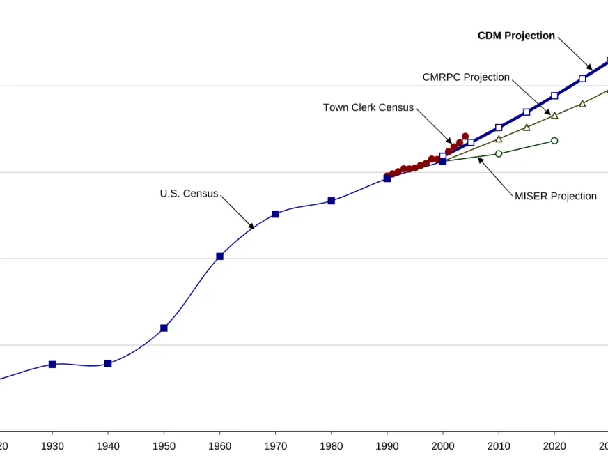
Historic and future population trends are generally used to predict future water consumption for a community. In order to estimate the future water supply needs for the town, past population trends and future population projections from several independent sources were reviewed. The various sources were:
United States Census Bureau (USCB) Town Clerk’s Office, Town of Holden
Massachusetts Institute for Social and Economic Research (MISER) Central Massachusetts Regional Planning Commission (CMRPC)
Table 3-1 and Figure 3-1 show the historic census population in Holden from 1920. In general, the population of the town has steadily grown since 1920, as residents continue to seek suburban homes. While the rate of growth from 1920 to 1930 was 30 percent, population remained nearly constant from 1930 to 1940. From 1940 to 1950 and 1950 to 1960, Holden experienced its greatest growth rate of 52 percent and 69 percent, respectively. However, this significant population growth did not last, since the rates of growth from 1960 to 2000 for each ten-year period were 24, 6, 10, and 7 percent, respectively.
Table 3-1
USCB Population Census
Year USCB
Population Count
Percentage Increase/Decrease Over Previous Census Year 1920 1930 1940 1950 1960 1970 1980 1990 2000 2,970 3,871 3,924 5,975 10,117 12,564 13,336 14,628 15,621 -- +30 +1.4 +52 +69 +24 +6.1 +10 +6.8 USCB: United States Census Bureau
A
3-1In addition to the USCB data, the Town Clerk’s Office also develops annual population estimates for the Town of Holden. The Town Clerk’s Office annual population estimates for Holden from 1990 to the present are listed in Table 3-2 and shown in Figure 3-1:
Table 3-2
Town Clerk Population Census
Year Town Clerk
Population Count
Percentage Increase/Decrease Over Previous Year 1990 1991 1992 1993 1994 1995 1996 1997 1998 1999 2000 2001 2002 2003 2004 14,767 14,895 15,017 15,191 15,178 15,240 15,384 15,505 15,750 15,730 15,911 16,184 16,455 16,695 17,072 -- +0.9 +0.8 +1.2 -0.1 +0.4 +0.9 +0.8 +1.6 -0.1 +1.2 +1.7 +1.7 +1.5 +2.3 Source: Town Assessor
In 2003, MISER released the latest population projections for Massachusetts and its counties, cities and towns for the years 2010 and 2020. The latest population
projections incorporate the 2000 U.S. Census information and include a middle, high, and low projection series. The MISER population projections for Holden are listed below:
Year Low Population Projection Mid Population Projection High Population Projection 2010 2020 14,964 14,180 15,504 15,453 16,058 16,818 Source: MISER, 2003
The MISER’s high population projection for Holden is shown on Figure 3-1. CMRPC, a planning partnership serving central and southern Worcester County communities in the areas of growth and development management, transportation planning, information coordination and data management, regularly updates