Ultrasonic process gas flowmeter
ER 1.1.7_3 www.krohne.com 08/2018 - 4001102304 - MA OPTISONIC 7300 R04 en
1 Safety instructions
6
1.1 Software history ... 6
1.2 Intended use ... 7
1.3 Certification ... 7
1.4 Safety instructions from the manufacturer ... 8
1.4.1 Copyright and data protection ... 8
1.4.2 Disclaimer ... 8
1.4.3 Product liability and warranty ... 9
1.4.4 Information concerning the documentation... 9
1.4.5 Warnings and symbols used... 10
1.5 Safety instructions for the operator... 10
2 Device description
11
2.1 Scope of delivery... 11
2.2 Device description ... 12
2.2.1 Field housing... 13
2.3 Nameplates ... 14
2.3.1 Example of nameplate for the compact version ... 14
2.3.2 Example of nameplate for the flow sensor (remote version) ... 15
2.3.3 Examples of nameplates on the signal converter (field housing) ... 15
3 Installation
17
3.1 General notes on installation ... 17
3.2 Storage ... 17
3.3 Transport ... 17
3.4 Pre-installation requirements ... 18
3.5 General requirements ... 18
3.5.1 Vibration ... 18
3.6 Installation requirements for the flow sensor... 19
3.7 Installation conditions ... 19
3.7.1 Inlet and outlet ... 19
3.7.2 T-section ... 20
3.7.3 Control valve ... 20
3.7.4 Flange deviation ... 20
3.7.5 Installation position ... 21
3.7.6 Thermal insulation... 22
3.8 Mounting the field housing, remote version ... 23
3.8.1 Pipe mounting ... 23
3.8.2 Turning the display of the field housing version ... 24
4 Electrical connections
25
4.1 Safety instructions... 25
4.2 Connection of signal cable to signal converter (remote version only)... 25
4.3 Power supply connection ... 27
4.4 Laying electrical cables correctly ... 28
4.5.1 Combinations of the inputs/outputs (I/Os) ... 29
4.5.2 Description of the CG number ... 30
4.5.3 Fixed, non-alterable input/output versions... 31
4.5.4 Alterable input/output versions... 32
4.6 Description of the inputs and outputs... 33
4.6.1 Current output ... 33
4.6.2 Pulse output and frequency output ... 34
4.6.3 Status output and limit switch ... 35
4.6.4 Control input ... 36
4.6.5 Current input... 37
4.7 Connection diagrams of inputs and outputs ... 38
4.7.1 Important notes... 38
4.7.2 Description of the electrical symbols... 39
4.7.3 Basic inputs/outputs ... 40
4.7.4 Modular inputs/outputs and bus systems ... 43
4.7.5 Ex i inputs/outputs ... 52
4.7.6 HART connection... 57
5 Start-up
58
5.1 Switching on the power ... 58
5.2 Starting the signal converter ... 58
6 Operation
59
6.1 Display and operating elements ... 59
6.1.1 Display in measuring mode with 2 or 3 measured values ... 61
6.1.2 Display for selection of submenu and functions, 3 lines ... 61
6.1.3 Display when setting parameters, 4 lines ... 62
6.1.4 Display when previewing parameters, 4 lines... 62
6.1.5 Using an IR interface (option) ... 63
6.2 Menu overview... 64
6.3 Function tables ... 67
6.3.1 Menu A; quick setup... 67
6.3.2 Menu B; test ... 68
6.3.3 Menu C; setup ... 70
6.3.4 Set free units... 83
6.4 Description of functions ... 84
5 www.krohne.com 08/2018 - 4001102304 - MA OPTISONIC 7300 R04 en
8 Technical data
90
8.1 Measuring principle... 90
8.2 Technical data... 91
8.3 Dimensions and weight ... 103
8.3.1 Flow sensor in carbon steel... 104
8.3.2 Signal converter housing ... 108
8.3.3 Mounting plate of field housing ... 109
9 Description of HART interface
110
9.1 General description ... 110
9.2 Software history ... 110
9.3 Connection variants... 111
9.3.1 Point-to-Point connection - analogue / digital mode... 112
9.3.2 Multi-drop connection (2-wire connection)... 113
9.3.3 Multi-drop connection (3-wire connection)... 114
9.4 Inputs/outputs and HART dynamic variables and device variables ... 115
9.5 Remote operation ... 116
9.5.1 Online/offline operation ... 116
9.5.2 Parameters for the basic configuration ... 117
9.5.3 Units ... 117
9.6 Field Communicator 375/475 (FC 375/475) ... 117
9.6.1 Installation ... 117
9.6.2 Operation... 118
9.7 Asset Management Solutions (AMS
®) ... 119
9.7.1 Installation ... 119
9.7.2 Operation... 119
9.8 Process Device Manager (PDM)... 120
9.8.1 Installation ... 120
9.8.2 Operation... 120
9.9 Field Device Manager (FDM) ... 121
9.9.1 Installation ... 121
9.9.2 Operation... 121
9.10 Field Device Tool Device Type Manager (FDT DTM) ... 121
9.10.1 Installation ... 121
9.10.2 Operation... 121
9.11 HART Menu Tree... 122
9.11.1 HART Menu Tree - Field Communicator HART Application... 122
9.11.2 HART Menu Tree AMS - Device's context menu ... 123
9.11.3 HART Menu Tree PDM - Menu Bar and Working Window ... 124
9.11.4 HART Menu Tree FDM - Device Configuration ... 125
9.11.5 Description of used abbreviations ... 125
9.11.6 Process Variables Root Menu... 126
9.11.7 Diagnostic Root Menu ... 127
9.11.8 Device Root Menu... 129
9.11.9 Offline Root Menu... 132
1.1 Software history
For all GDC devices, the "Electronic Revision" (ER) is consulted to document the revision status of the electronics according to NE 53. It is easy to see from the ER whether any fault repairs or major changes to the electronic equipment have taken place and what effect they have had on compatibility.
1 Downwards compatible changes and fault repair with no effect on operation (e.g. spelling mistakes on display)
2-_ Downwards compatible hardware and/or software change of interfaces: H HART® version 7
F Foundation Fieldbus M Modbus
X all interfaces
3-_ Downwards compatible hardware and/or software change of inputs and outputs I Current output
F, P Frequency output, pulse output S Status output
C Control input
X all inputs and outputs
4 Downwards compatible changes with new functions
5 Incompatible changes, i.e. electronic equipment must be changed Table 1-1: Description of changes
INFORMATION!
In the table below, "x" is a place holder for possible multi-digit alphanumeric combinations,
depending on the available version.
Release date Electronic revision Changes and
compatibility Documentation
2010 ER 1.0.0_ MA OPTISONIC 7300 R01
2012 ER 1.1.0_ MA OPTISONIC 7300 R02
2014 ER 1.1.1_ MA OPTISONIC 7300 R03
2017-09 ER 1.1.7_ 5 MA OPTISONIC 7300 R04 Table 1-2: Changes and effect on compatibility
7
www.krohne.com 08/2018 - 4001102304 - MA OPTISONIC 7300 R04 en
1.2 Intended use
The OPTISONIC 7300OPTISONIC 7300OPTISONIC 7300OPTISONIC 7300 is designed exclusively for bi-directional measurement of process gases in closed completely filled pipeline circuits. Excess of contaminations (moisture, particles,
2 phases) disturb the acoustic signal and must be avoided.
The overall functionality of the gas flowmeter is the continuous measurement of actual volume flow, corrected volume flow, mass flow, molar mass, flow speed, velocity of sound, gain, SNR and diagnosis value.
1.3 Certification
This device fulfils the statutory requirements of the relevant EU directives.
For full information of the EU directives and standards and the approved certifications, please refer to the EU Declaration of Conformity or the website of the manufacturer.
CAUTION!
Responsibility for the use of the measuring devices with regard to suitability, intended use and
corrosion resistance of the used materials against the measured fluid lies solely with the
operator.
INFORMATION!
The manufacturer is not liable for any damage resulting from improper use or use for other than
the intended purpose.
CE marking
The manufacturer certifies successful testing of the product by applying the CE marking.
DANGER!
For devices used in hazardous areas, additional safety notes apply; please refer to the Ex
documentation.
1.4 Safety instructions from the manufacturer
1.4.1 Copyright and data protection
The contents of this document have been created with great care. Nevertheless, we provide no guarantee that the contents are correct, complete or up-to-date.
The contents and works in this document are subject to copyright. Contributions from third parties are identified as such. Reproduction, processing, dissemination and any type of use beyond what is permitted under copyright requires written authorisation from the respective author and/or the manufacturer.
The manufacturer tries always to observe the copyrights of others, and to draw on works created in-house or works in the public domain.
The collection of personal data (such as names, street addresses or e-mail addresses) in the manufacturer's documents is always on a voluntary basis whenever possible. Whenever feasible, it is always possible to make use of the offerings and services without providing any personal data.
We draw your attention to the fact that data transmission over the Internet (e.g. when
communicating by e-mail) may involve gaps in security. It is not possible to protect such data completely against access by third parties.
We hereby expressly prohibit the use of the contact data published as part of our duty to publish an imprint for the purpose of sending us any advertising or informational materials that we have not expressly requested.
1.4.2 Disclaimer
The manufacturer will not be liable for any damage of any kind by using its product, including, but not limited to direct, indirect or incidental and consequential damages.
This disclaimer does not apply in case the manufacturer has acted on purpose or with gross negligence. In the event any applicable law does not allow such limitations on implied warranties or the exclusion of limitation of certain damages, you may, if such law applies to you, not be subject to some or all of the above disclaimer, exclusions or limitations.
Any product purchased from the manufacturer is warranted in accordance with the relevant product documentation and our Terms and Conditions of Sale.
9
www.krohne.com 08/2018 - 4001102304 - MA OPTISONIC 7300 R04 en
1.4.3 Product liability and warranty
The operator shall bear responsibility for the suitability of the device for the specific purpose. The manufacturer accepts no liability for the consequences of misuse by the operator. Improper installation or operation of the devices (systems) will cause the warranty to be void. The
respective "Standard Terms and Conditions" which form the basis for the sales contract shall also apply.
1.4.4 Information concerning the documentation
To prevent any injury to the user or damage to the device it is essential that you read the information in this document and observe applicable national standards, safety requirements and accident prevention regulations.
If this document is not in your native language and if you have any problems understanding the text, we advise you to contact your local office for assistance. The manufacturer can not accept responsibility for any damage or injury caused by misunderstanding of the information in this document.
This document is provided to help you establish operating conditions, which will permit safe and efficient use of this device. Special considerations and precautions are also described in the document, which appear in the form of icons as shown below.
1.4.5 Warnings and symbols used
Safety warnings are indicated by the following symbols.
• HANDLINGHANDLINGHANDLINGHANDLING
This symbol designates all instructions for actions to be carried out by the operator in the specified sequence.
DANGER!
This warning refers to the immediate danger when working with electricity.
DANGER!
This warning refers to the immediate danger of burns caused by heat or hot surfaces.
DANGER!
This warning refers to the immediate danger when using this device in a hazardous atmosphere.
DANGER!
These warnings must be observed without fail. Even partial disregard of this warning can lead to
serious health problems and even death. There is also the risk of seriously damaging the device
or parts of the operator's plant.
WARNING!
Disregarding this safety warning, even if only in part, poses the risk of serious health problems.
There is also the risk of damaging the device or parts of the operator's plant.
CAUTION!
Disregarding these instructions can result in damage to the device or to parts of the operator's
plant.
INFORMATION!
These instructions contain important information for the handling of the device.
LEGAL NOTICE!
11
www.krohne.com 08/2018 - 4001102304 - MA OPTISONIC 7300 R04 en
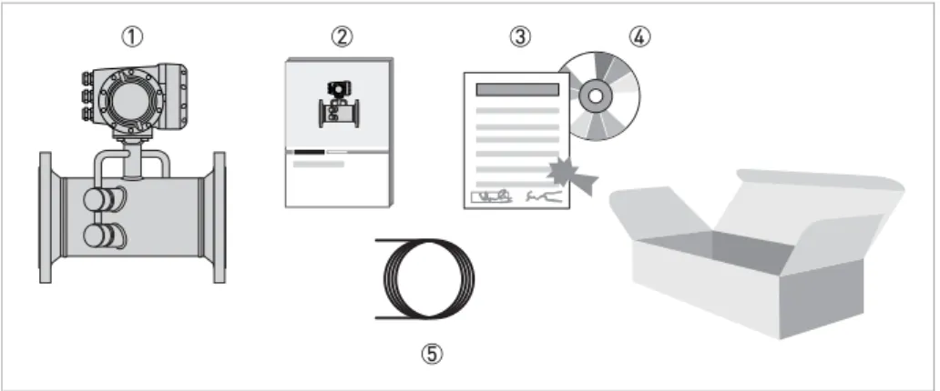
2.1 Scope of delivery
INFORMATION!
Do a check of the packing list to make sure that you have all the elements given in the order.
INFORMATION!
Inspect the packaging carefully for damages or signs of rough handling. Report damage to the
carrier and to the local office of the manufacturer.
INFORMATION!
The field device will arrive in two cartons. One carton contains the converter and one carton
contains the sensor.
Make sure to combine the correct devices together by comparing the serial numbers
Figure 2-1: Scope of delivery 1 Ordered flowmeter
2 Product documentation
3 Factory calibration certificate
4 CD-ROM with product documentation in available languages
5 Signal cable (remote versions only)
INFORMATION!
Assembly materials and tools are not part of the delivery. Use the assembly materials and tools
in compliance with the applicable occupational health and safety directives.
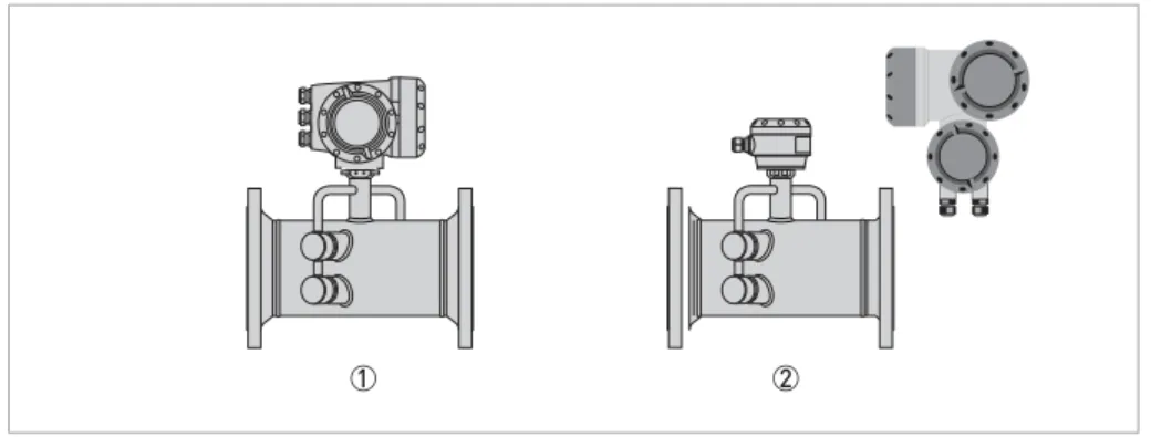
2.2 Device description
The ultrasonic flowmeters are designed exclusively for the continuous measurement of actual volume flow, corrected volume flow, mass flow, molar mass, flow speed, velocity of sound, gain, SNR and diagnosis value.
Your measuring device is supplied ready for operation. The factory settings for the operating data have been made in accordance with your order specifications.
The following versions are available:
• Compact version (the signal converter is mounted directly on the flow sensor)
• Remote version (electrical connection to the flow sensor via signal cable)
INFORMATION!
Product specific information and extensive product specification is available using PICK, the
Product Information Center KROHNE web-tool.
PICK can be found via the service menu button on the KROHNE.com website.
Figure 2-2: Device versions 1 Compact version
13
www.krohne.com 08/2018 - 4001102304 - MA OPTISONIC 7300 R04 en
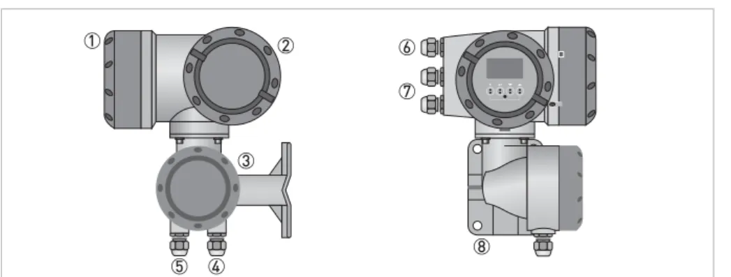
2.2.1 Field housing
Figure 2-3: Construction of the field housing 1 Cover for electronics and display
2 Cover for power supply and inputs/outputs terminal compartment
3 Cover for flow sensor terminal compartment
4 Use cable entry 4 and/or 5 for flow sensor signal cable
5 (see 4)
6 Cable entry for power supply
7 Cable entry for inputs and outputs
8 Mounting plate for pipe and wall mounting
INFORMATION!
Each time a housing cover is opened, the thread should be cleaned and greased.
Use only resin-free and acid-free grease.
2.3 Nameplates
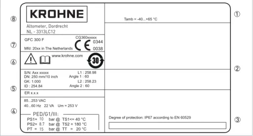
2.3.1 Example of nameplate for the compact version
INFORMATION!
Look at the device nameplate to ensure that the device is delivered according to your order.
Check for the correct supply voltage printed on the nameplate.
1 Ambient temperature
2 Space for additional information
3 Protection class and Tag number
4 Main supply and PED data
5 Calibration data and electronics revision number (ER)
6 Info / web address and Rohs logo
7 Type designation and manufacturer date of the flowmeter / CE sign with number(s) of notified body / bodies
15
www.krohne.com 08/2018 - 4001102304 - MA OPTISONIC 7300 R04 en
2.3.2 Example of nameplate for the flow sensor (remote version)
2.3.3 Examples of nameplates on the signal converter (field housing)
Figure 2-4: Example of nameplate 1 Ambient temperature
2 Protection class
3 Tag number
4 PED data
5 Calibration data
6 Type designation and manufacturer date of the flowmeter / CE sign with number(s) of notified body / bodies
7 Name and address of the manufacturer
Figure 2-5: Example of nameplate 1 Ambient temperature
2 Space for additional information
3 Protection class and Tag number
4 Main supply and PED data
5 Calibration data and electronics revision number (ER)
6 Info / web address and Rohs logo
7 Type designation and manufacturer date of the flowmeter / CE sign with number(s) of notified body / bodies
8 Name and address of the manufacturer
PED/G1/III: 10 8.7 15 Altometer, Dordrecht NL - 3313LC12
Electrical connection data of inputs/outputs (example of basic version) Electrical connection data of inputs/outputs (example of basic version) Electrical connection data of inputs/outputs (example of basic version) Electrical connection data of inputs/outputs (example of basic version)
• A = active mode; the signal converter supplies the power for connection of the subsequent devices
• P = passive mode; external power supply required for operation of the subsequent devices
• N/C = connection terminals not connected
Figure 2-6: Example of a nameplate for electrical connection data of inputs and outputs 1 Power supply (AC: L and N; DC: L+ and L-; PE for t 24 VAC; FE for d 24 VAC and DC)
2 Connection data of connection terminal
D/D-3 Connection data of connection terminal
C/C-4 Connection data of connection terminal
B/B-5 Connection data of connection terminal A/A-; A+ only operable in the basic version
WARNING!
Do not use the terminals A+ and A- at the same time. The system will be damaged by the direct
voltage of 24 VDC and a 1 A peak current.
17
www.krohne.com 08/2018 - 4001102304 - MA OPTISONIC 7300 R04 en
3.1 General notes on installation
3.2 Storage
• Store the device in a dry, dust-free location.
• Avoid continuous direct sunlight.
• Store the device in its original packaging.
• Storage temperature: -50...+70°C / -58...+158°F
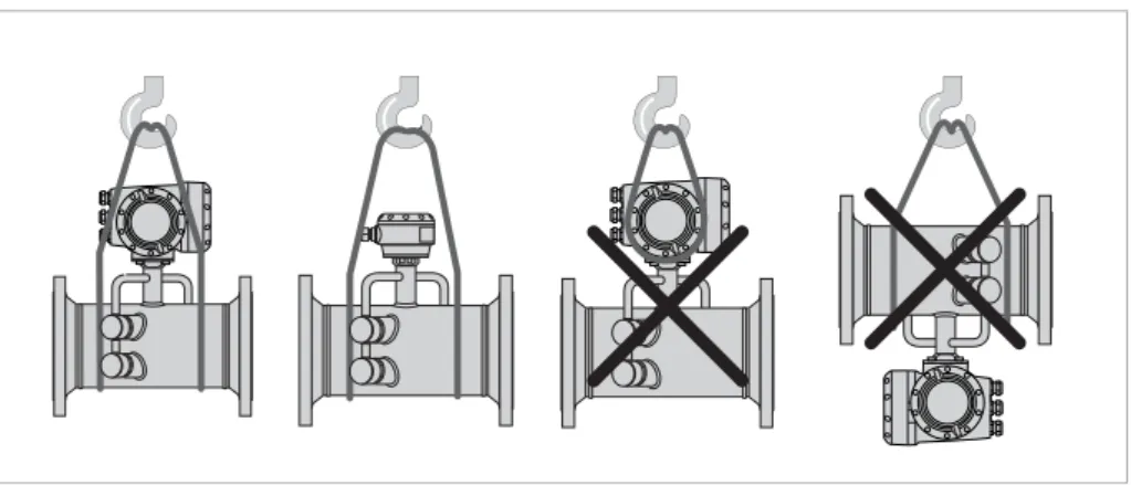
3.3 Transport
Signal converter
• Do not lift the signal converter by the cable glands.
Flow sensor
• Do not lift the flow sensor by the connection box.
• Use hoisting belts only.
• To transport flange devices, use lifting straps. Wrap these around both process connections.
INFORMATION!
Inspect the packaging carefully for damages or signs of rough handling. Report damage to the
carrier and to the local office of the manufacturer.
INFORMATION!
Do a check of the packing list to make sure that you have all the elements given in the order.
INFORMATION!
Look at the device nameplate to ensure that the device is delivered according to your order.
Check for the correct supply voltage printed on the nameplate.
3.4 Pre-installation requirements
Make sure that you have all necessary tools available:
• Allen key (4 and 5 mm)• Small screwdriver
• Wrench for cable glands and for pipe mounting bracket (remote version only); refer to
Mounting the field housing, remote version
on page 233.5 General requirements
3.5.1 Vibration
INFORMATION!
To assure a quick, safe and uncomplicated installation, we kindly request you to make provisions
as stated below.
INFORMATION!
The following precautions must be taken to ensure reliable installation.
•Make sure that there is adequate space to the sides.
•
Protect the signal converter from direct sunlight and install a sun shade if necessary.
•Signal converters installed in control cabinets require adequate cooling, e.g. by fan or heat
exchanger.
•
Do not expose the signal converter to intense vibrations.
Figure 3-2: Avoid vibrations
INFORMATION!
19
www.krohne.com 08/2018 - 4001102304 - MA OPTISONIC 7300 R04 en
3.6 Installation requirements for the flow sensor
To secure the optimum functioning of the flowmeter, please note the following observations. The OPTISONIC 7300 is designed for the measurement dry gas flow. Excess of liquids may disturb the acoustic signals and should thus be avoided.
The following guidelines should be observed in case occasional small amounts of liquids are to be expected:
• Install the flow sensor in a horizontal position in a slightly descending line.
• Orientate the flow sensor such that the path of the acoustic signal is in the horizontal plane. For exchanging the transducers, please keep a free space of 1 m / 39" around the transducer.
3.7 Installation conditions
3.7.1 Inlet and outlet
1 path flowmeter
Figure 3-3: Recommended inlet and oulet for d DN80 / 3" 1 t 20 DN
2 t 3 DN
2 path flowmeter
Figure 3-4: Recommended inlet and oulet for t DN100 / 4" 1 t 10 DN
3.7.2 T-section
3.7.3 Control valve
Install the flowmeter upstream of a control valve.
3.7.4 Flange deviation
Figure 3-5: Distance behind a T-section 1 2 path t 10 DN, 1 path t 20 DN
CAUTION!
In case valve noise is expected (large pressure drop over valve or pressure reducer in the same
pipeline as the flowmeter), please contact the manufacturer.
Figure 3-6: Not recommended installation of the flowmeter and valve in the same pipeline
CAUTION!
Max. permissible deviation of pipe flange faces:
L
max- L
mind
0.5 mm / 0.02"
21
www.krohne.com 08/2018 - 4001102304 - MA OPTISONIC 7300 R04 en
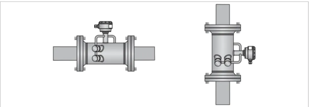
3.7.5 Installation position
• Horizontal: install the flow sensor in a horizontal position in case of the presence of liquids.
• Vertically +15
+15 +15
+15° < < < < D < -15 < -15 < -15 < -15°
• Horizontal or vertical: allowed installation position in case of dry gas. Figure 3-8: Installation position
3.7.6 Thermal insulation
CAUTION!
The flow sensor can be insulated completely, except for the transducers
1
and the connection
box
2
to allow cooling by free air convection.
WARNING!
Always leave vent holes
3
free!
DANGER!
For devices in hazardous area, additional maximum temperature and insulation precautions
apply. Please refer to the Ex documentation.
Figure 3-10: Leave vent holes free 1 Transducers
2 Connection box
23
www.krohne.com 08/2018 - 4001102304 - MA OPTISONIC 7300 R04 en
3.8 Mounting the field housing, remote version
3.8.1 Pipe mounting
1 Fix the signal converter to the pipe.
2 Fasten the signal converter using standard U-bolts and washers. 3 Tighten the nuts.
INFORMATION!
Assembly materials and tools are not part of the delivery. Use the assembly materials and tools
in compliance with the applicable occupational health and safety directives.
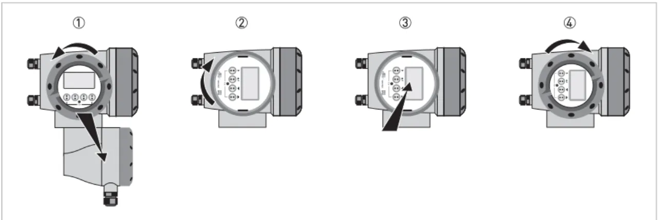
3.8.2 Turning the display of the field housing version
The display of the field housing version can be turned in 90
°
increments
1 Unscrew the cover from the display and operation control unit. 2 Pull out the display and rotate it to the required position. 3 Slide the display back into the housing.
4 Re-fit the cover and tighten it by hand. Figure 3-12: Turning the display of the field housing version
CAUTION!
The ribbon cable of the display must not be folded or twisted repeatedly.
INFORMATION!
Each time a housing cover is opened, the thread should be cleaned and greased. Use only
resin-free and acid-resin-free grease.
25
www.krohne.com 08/2018 - 4001102304 - MA OPTISONIC 7300 R04 en
4.1 Safety instructions
4.2 Connection of signal cable to signal converter (remote version only)
The flow sensor is connected to the signal converter via one or two signal cables, with 2 inner triax cables for the connection of one or two acoustic path(s). A flow sensor with one acoustic path has one cable. A flow sensor with two acoustic paths has two cables.
DANGER!
All work on the electrical connections may only be carried out with the power disconnected. Take
note of the voltage data on the nameplate!
DANGER!
Observe the national regulations for electrical installations!
DANGER!
For devices used in hazardous areas, additional safety notes apply; please refer to the Ex
documentation.
WARNING!
Observe without fail the local occupational health and safety regulations. Any work done on the
electrical components of the measuring device may only be carried out by properly trained
specialists.
INFORMATION!
Look at the device nameplate to ensure that the device is delivered according to your order.
Check for the correct supply voltage printed on the nameplate.
Figure 4-1: Connection of signal cable to signal converter 1 Signal converter
2 Open connection box
3 Tool for releasing connectors
4 Marking on cable
CAUTION!
To ensure smooth functioning, always use the signal cable(s) included in the delivery.
Figure 4-2: Clamp the cables on the shielding bush 1 Cables
2 Cable glands
3 Grounding clamps
27
www.krohne.com 08/2018 - 4001102304 - MA OPTISONIC 7300 R04 en
4.3 Power supply connection
WARNING!
When this device is intended for permanent connection to the mains.
It is required (for example for service) to mount an external switch or circuit breaker near the
device for disconnection from the mains. It shall be easily reachable by the operator and marked
as the disconnecting the device for this equipment.
The switch or circuit breaker and wiring has to be suitable for the application and shall also be in
accordance with the local (safety) requirements of the (building) installation
(e.g. IEC 60947-1/-3)
DANGER!
For devices used in hazardous areas, additional safety notes apply; please refer to the Ex
documentation.
INFORMATION!
The power terminals in the terminal compartments are equipped with additional hinged lids to
prevent accidental contact.
Figure 4-4: Power supply connection 1 100...230 VAC (-15% / +10%), 22 VA
2 24 VDC (-55% / +30%), 12 W
3 24 VAC/DC (AC: -15% / +10%; DC: -25% / +30%), 22 VA or 12 W
DANGER!
The device must be grounded in accordance with regulations in order to protect personnel
against electric shocks.
100...230 VAC (tolerance range for 100 VAC: -15% / +10%)
100...230 VAC (tolerance range for 100 VAC: -15% / +10%)
100...230 VAC (tolerance range for 100 VAC: -15% / +10%)
100...230 VAC (tolerance range for 100 VAC: -15% / +10%)
• Note the power supply voltage and frequency (50...60 Hz) on the nameplate.
• The protective ground terminal PEPEPE of the power supply must be connected to the separate U-PE clamp terminal in the terminal compartment of the signal converter
24 VDC (tolerance range: -55% / +30%)
24 VDC (tolerance range: -55% / +30%)
24 VDC (tolerance range: -55% / +30%)
24 VDC (tolerance range: -55% / +30%)
24 VAC/DC (tolerance range: AC: -15% / +10%; DC: -25% / +30%)
24 VAC/DC (tolerance range: AC: -15% / +10%; DC: -25% / +30%)
24 VAC/DC (tolerance range: AC: -15% / +10%; DC: -25% / +30%)
24 VAC/DC (tolerance range: AC: -15% / +10%; DC: -25% / +30%)
• Note the data on the nameplate!• For measurement process reasons, a functional ground FEFEFEFE must be connected to the separate U-clamp terminal in the terminal compartment of the signal converter.
• When connecting to functional extra-low voltages, provide a facility for protective separation (PELV) (according to VDE 0100 / VDE 0106 and/or IEC 60364 / IEC 61140 or relevant national regulations)
4.4 Laying electrical cables correctly
1 Lay the cable in a loop just before the housing.
2 Tighten the screw connection of the cable entry securely. 3 Never mount the housing with the cable entries facing upwards. 4 Seal cable entries that are not needed with a plug.
INFORMATION!
240 VAC + 5% is included in the tolerance range.
29
www.krohne.com 08/2018 - 4001102304 - MA OPTISONIC 7300 R04 en
4.5 Inputs and outputs, overview
4.5.1 Combinations of the inputs/outputs (I/Os)
This signal converter is available with various input/output combinations.
Basic version
• Has 1 current output, 1 pulse output and 2 status outputs/limit switches.
• The pulse output can be set as status output/limit switch and one of the status outputs as a control input.
Ex i version
• Depending on the task, the device can be configured with various output modules.
• Current outputs can be active or passive.
• Optionally available also with Foundation Fieldbus.
Modular version
• Depending on the task, the device can be configured with various output modules.
Bus systems
• The device allows intrinsically safe and non intrinsically safe bus interfaces in combination with additional modules.
• For connection and operation of bus systems, please note the supplementary documentation.
Ex option
• For hazardous areas, all of the input/output variants for the housing designs with terminal compartment in the Ex d (pressure-resistant casing) or Ex e (increased safety) versions can be delivered.
4.5.2 Description of the CG number
The last 3 digits of the CG number (5, 6 and 7) indicate the assignment of the terminal connections. Please see the following examples.
Examples for CG number
Figure 4-6: Marking (CG number) of the electronics module and input/output variants 1 ID number: 6
2 ID number: 0 = standard
3 Power supply option
4 Display (language versions)
5 Input/output version (I/O)
6 1st optional module for connection terminal A
7 2nd optional module for connection terminal B
CG 360 11 100 100...230 VAC & standard display; basic I/O: Ia or Ip & Sp/Cp & Sp & Pp/Sp
CG 360 11 7FK 100...230 VAC & standard display; modular I/O: Ia & PN/SN and optional module PN/SN & CN
CG 360 81 4EB 24 VDC & standard display; modular I/O: Ia & Pa/Sa and optional module Pp/Sp & Ip
Abbreviation Identifier for CG no. Description
Ia A Active current output
Ip B Passive current output
Pa / Sa C Active pulse output, frequency output, status output or limit switch
(changeable)
Pp / Sp E Passive pulse output, frequency output, status output or limit switch
(changeable)
PN / SN F Passive pulse output, frequency output, status output or limit switch
according to NAMUR (changeable)
Ca G Active control input
Cp K Passive control input
CN H Active control input to NAMUR
Signal converter monitors cable breaks and short circuits according to EN 60947-5-6. Errors indicated on LC display.
31
www.krohne.com 08/2018 - 4001102304 - MA OPTISONIC 7300 R04 en
4.5.3 Fixed, non-alterable input/output versions
This signal converter is available with various input/output combinations.
• The grey boxes in the tables denote unassigned or unused connection terminals.
• In the table, only the final digits of the CG no. are depicted.
• Connection terminal A+ is only operable in the basic input/output version.
CG no. Connection terminals
A+ A A- B B- C C- D
D-Basic I/Os (standard)
1 0 0 Ip + HART® passive 1 Sp / Cp passive 2 Sp passive Pp / Sp passive 2
Ia + HART® active 1
Ex i I/Os (option)
2 0 0 Ia + HART® active PN / SN NAMUR 2
3 0 0 Ip + HART® passive PN / SN NAMUR 2
2 1 0 Ia active PN / SNNAMUR Cp passive 2 Ia + HART ® active PN / SN NAMUR 2 3 1 0 Ia active PN / SNNAMUR Cp passive 2 Ip + HART ® passive PN / SN NAMUR 2 2 2 0 Ip passive PN / SNNAMUR Cp passive 2 Ia + HART ® active PN / SNNAMUR 2 3 2 0 Ip passive PN / SNNAMUR Cp passive 2 Ip + HART ® passive PN / SNNAMUR 2
2 3 0 IIna active PN / SNNAMUR
Cp passive 2 Ia + HART
® active PN / SNNAMUR 2
3 3 0 IIna active PN / SNNAMUR
Cp passive 2 Ip + HART
® passive PN / SNNAMUR 2
2 4 0 IInp passive PN / SNNAMUR
Cp passive 2 Ia + HART
® active PN / SNNAMUR 2
3 4 0 IInp passive PN / SNNAMUR
Cp passive 2 Ip + HART
® passive PN / SNNAMUR 2
2 5 0 IIna active IIna active
1Function changed by reconnecting
4.5.4 Alterable input/output versions
This signal converter is available with various input/output combinations.
• The grey boxes in the tables denote unassigned or unused connection terminals.
• In the table, only the final digits of the CG no. are depicted.
• Term. = (connection) terminal
CG no. Connection terminals
A+ A A- B B- C C- D
D-Modular IOs (option)
4 _ _ max. 2 optional modules for term. A + B Ia + HART® active Pa / Sa active 1
8 _ _ max. 2 optional modules for term. A + B I
p + HART® passive Pa / Sa active 1
6 _ _ max. 2 optional modules for term. A + B Ia + HART® active Pp / Sp passive 1
B _ _ max. 2 optional modules for term. A + B Ip + HART® passive Pp / Sp passive 1
7 _ _ max. 2 optional modules for term. A + B I
a + HART® active PN / SN NAMUR 1
C _ _ max. 2 optional modules for term. A + B Ip + HART® passive PN / SN NAMUR 1
FOUNDATION Fieldbus (option)
E _ _ max. 2 optional modules for term. A + B V/D+ (2) V/D- (2) V/D+ (1) V/D- (1)
Modbus (option)
G _ _ 2 max. 2 optional modules for term. A + B Common Sign. B
(D1) Sign. A (D0)
1Changeable
33
www.krohne.com 08/2018 - 4001102304 - MA OPTISONIC 7300 R04 en
4.6 Description of the inputs and outputs
4.6.1 Current output
• All outputs are electrically isolated from each other and from all other circuits.
• All operating data and functions can be adjusted.
• Passive mode:
External power Uextd32 VDC at Id22 mA
• Active mode:
Load impedance RLd1 k: at Id22 mA; RLd450: at Id22 mA for Ex i outputs
• Self-monitoring: interruption or load impedance too high in the current output loop
• Error message possible via status output, error indication on LC display.
• Current value error detection can be adjusted.
• Automatic range conversion via threshold or control input. The setting range for the threshold is between 5 and 80% of Q100%, ±0...5% hysteresis (corresponding ratio from smaller to larger range of 1:20 to 1:1.25).
Signaling of the active range possible via a status output (adjustable).
• Forward/reverse flow measurement (F/R mode) is possible.
INFORMATION!
The current outputs must be connected depending on the version! Which I/O version and
inputs/outputs are installed in your signal converter are indicated on the sticker in the cover of
the terminal compartment.
INFORMATION!
For further information refer to Connection diagrams of inputs and outputs on page 38
.DANGER!
For devices used in hazardous areas, additional safety notes apply; please refer to the Ex
documentation.
4.6.2 Pulse output and frequency output
• All outputs are electrically isolated from each other and from all other circuits.
• All operating data and functions can be adjusted.
• Passive mode:
External power supply required: Uextd32 VDC
Id20 mA at fd10 kHz (over range up to fmaxd12 kHz) Id100 mA at fd100 Hz
• Active mode:
Use of the internal power supply: Unom= 24 VDC Id20 mA at fd10 kHz (over range up to fmaxd12 kHz) Id20 mA at fd100 Hz
• NAMUR mode: passive in accordance with EN 60947-5-6, fd10 kHz, over range up to fmaxd12 kHz
• Scaling:
Frequency output: in pulses per time unit (e.g. 1000 pulses/s at Q100%); Pulse output: quantity per pulse.
• Pulse width:
symmetric (pulse duty factor 1:1, independent of output frequency) automatic (with fixed pulse width, duty factor approx. 1:1 at Q100%) or fixed (pulse width adjustable as required from 0.05 ms...2 s)
• Forward/reverse flow measurement (F/R mode) is possible.
• All pulse and frequency outputs can also be used as a status output / limit switch.
INFORMATION!
Depending on the version, the pulse and frequency outputs must be connected passively or
actively or according to NAMUR EN 60947-5-6! Which I/O version and inputs/outputs are
installed in your signal converter are indicated on the sticker in the cover of the terminal
compartment.
INFORMATION!
For further information refer to Connection diagrams of inputs and outputs on page 38
.DANGER!
For devices used in hazardous areas, additional safety notes apply; please refer to the Ex
documentation.
35
www.krohne.com 08/2018 - 4001102304 - MA OPTISONIC 7300 R04 en
4.6.3 Status output and limit switch
• The status outputs / limit switches are electrically isolated from each other and from all other circuits.
• The output stages of the status outputs/limit switches during simple active or passive operation behave like relay contacts and can be connected with any polarity.
• All operating data and functions can be adjusted.
• Passive mode:
External power supply required: Uextd32 VDC; Id100 mA For the Ex i I/O signal converter:
For the Ex i I/O signal converter:For the Ex i I/O signal converter: For the Ex i I/O signal converter:
NAMUR characteristic: 4.7 mA / 0.77 mA
• Active mode:
Use of the internal power supply: Unom= 24 VDC; Id20 mA
• For information on the adjustable operating states refer to
Function tables
on page 67.INFORMATION!
Depending on the version, the status outputs and limit switches must be connected passively or
actively or according to NAMUR EN 60947-5-6! Which I/O version and inputs/outputs are
installed in your signal converter are indicated on the sticker in the cover of the terminal
compartment.
INFORMATION!
For further information refer to Connection diagrams of inputs and outputs on page 38
.DANGER!
For devices used in hazardous areas, additional safety notes apply; please refer to the Ex
documentation.
4.6.4 Control input
• All control inputs are electrically isolated from each other and from all other circuits.
• All operating data and functions can be adjusted.
• Passive mode:
External power supply required: Uextd32 VDC
• Active mode:
Use of the internal power supply: Unom= 24 VDC
• NAMUR mode:
Passive in accordance with EN 60947-5-6
Active control input to NAMUR EN 60947-5-6: signal converter monitors cable breaks and short circuits according to EN 60947-5-6. Errors indicated on LC display. Error messages possible via status output.
• For information on the adjustable operating states refer to
Function tables
on page 67.INFORMATION!
Depending on the version, the control inputs must be connected passively or actively or
according to NAMUR EN 60947-5-6! Which I/O version and inputs/outputs are installed in your
signal converter are indicated on the sticker in the cover of the terminal compartment.
INFORMATION!
For further information refer to Connection diagrams of inputs and outputs on page 38
.DANGER!
For devices used in hazardous areas, additional safety notes apply; please refer to the Ex
documentation.
37
www.krohne.com 08/2018 - 4001102304 - MA OPTISONIC 7300 R04 en
4.6.5 Current input
• All current inputs are electrically isolated from each other and from all other circuits.
• All operating data and functions can be adjusted.
• Passive mode:
External power supply required: Uextd32 VDC
• Active mode:
Use of the internal power supply: Unom= 24 VDC
• For information on the adjustable operating states refer to
Function tables
on page 67.INFORMATION!
Depending on the version, the current inputs must be connected passively or actively! Which I/O
version and inputs/outputs are installed in your signal converter are indicated on the sticker in
the cover of the terminal compartment.
INFORMATION!
For further information refer to Connection diagrams of inputs and outputs on page 38
.DANGER!
For devices used in hazardous areas, additional safety notes apply; please refer to the Ex
documentation.
4.7 Connection diagrams of inputs and outputs
4.7.1 Important notes
• All groups are electrically isolated from each other and from all other input and output circuits.
• Passive mode: An external power supply is necessary to operate (activation) the subsequent devices (Uext).
• Active mode: The signal converter supplies the power for operation (activation) of the subsequent devices, observe max. operating data.
• Terminals that are not used should not have any conductive connection to other electrically conductive parts.
INFORMATION!
Depending on the version, the inputs/outputs must be connected passively or actively or
according to NAMUR EN 60947-5-6! Which I/O version and inputs/outputs are installed in your
signal converter are indicated on the sticker in the cover of the terminal compartment.
DANGER!
For devices used in hazardous areas, additional safety notes apply; please refer to the Ex
documentation.
Ia Ip Current output active or passive
Pa Pp Pulse/frequency output active or passive
PN Pulse/frequency output passive according to NAMUR EN 60947-5-6 Sa Sp Status output/limit switch active or passive
SN Status output/limit switch passive according to NAMUR EN 60947-5-6 Ca Cp Control input active or passive
CN Control input active according to NAMUR EN 60947-5-6.
Signal converter monitors cable breaks and short circuits according to EN 60947-5-6. Errors indicated on LC display. Error messages possible via status output.
IIna IInp Current input active or passive
39
www.krohne.com 08/2018 - 4001102304 - MA OPTISONIC 7300 R04 en
4.7.2 Description of the electrical symbols
mA meter
0...20 mA or 4...20 mA and other
RL is the internal resistance of the measuring point including the cable resistance
DC voltage source (Uext), external power supply, any connection polarity
DC voltage source (Uext), observe connection polarity according to connection diagrams
Internal DC voltage source
Controlled internal power source in the device
Electronic or electromagnetic counter
At frequencies above 100 Hz, shielded cables must be used to connect the counters.
Ri Internal resistance of the counter
Button, N/O contact or similar
4.7.3 Basic inputs/outputs
Current output active (HART
®), basic I/Os
• Uint, nom= 24 VDC nominal• Id22 mA
• RLd1 k:
• Don't connect the terminals A+ and A- directly to an external input. This will damage the external device!
Current output passive (HART
®), basic I/Os
• Uint, nom= 24 VDC nominal• Uextd32 VDC
• Id22 mA
• U0t1.8 V
• RLd(Uext- U0) / Imax
CAUTION!
Observe connection polarity.
41
www.krohne.com 08/2018 - 4001102304 - MA OPTISONIC 7300 R04 en
Pulse/frequency output passive, basic I/Os
• Uextd32 VDC• fmax in operating menu set to fmaxd100 Hz: Id100 mA open: Id0.05 mA at Uext= 32 VDC closed: U0, max= 0.2 V at Id10 mA U0, max= 2 V at Id100 mA
• fmax in the operating menu set to 100 Hz < fmaxd10 kHz: Id20 mA open: Id0.05 mA at Uext= 32 VDC closed: U0, max= 1.5 V at I d 1 mA U0, max= 2.5 V at Id10 mA U0, max= 5.0 V at Id20 mA
• If the following maximum load resistance RL, max is exceeded, the load resistance RL must be reduced accordingly by parallel connection of R:
fd100 Hz: RL, max= 47 k:
fd1 kHz: RL, max= 10 k:
fd10 kHz: RL, max= 1 k:
• The minimum load resistance RL, min is calculated as follows: RL, min= (Uext- U0) / Imax
• Can also be set as status output; for the electrical connection refer to status output connection diagram.
INFORMATION!
•
Compact and field housing versions:
Compact and field housing versions: Shield connected via the cable terminals in the terminal
Compact and field housing versions:
Compact and field housing versions:
compartment.
Wall-mounted versions:
Wall-mounted versions:
Wall-mounted versions:
Wall-mounted versions: Shield connected using 6.3 mm / 0.25" push-on connectors in the
terminal compartment.
•
Any connection polarity.
Status output / limit switch passive, basic I/Os
• Uextd32 VDC• Id100 mA
• RL, max= 47 k:
RL, min= (Uext- U0) / Imax
• open:
Id0.05 mA at Uext= 32 VDC closed:
U0, max= 0.2 V at Id10 mA U0, max= 2 V at Id100 mA
• The output is open when the device is de-energised.
• X stands for the terminals B, C or D. The functions of the connection terminals depend on the settings refer to
Function tables
on page 67.Control input passive, basic I/Os
• 8 VdUextd32 VDC• Imax= 6.5 mA at Uextd24 VDC Imax= 8.2 mA at Uextd32 VDC
• Switching point for identifying "contact open or closed": Contact open (off): U0d2.5 V at Inom= 0.4 mA
Contact closed (on): U0t8 V at Inom= 2.8 mA
• Can also be set as a status output; for the electrical connection refer to status output
INFORMATION!
•
Any connection polarity.
43
www.krohne.com 08/2018 - 4001102304 - MA OPTISONIC 7300 R04 en
4.7.4 Modular inputs/outputs and bus systems
Current output active (only current output terminals C/C- have HART
®capability),
modular I/Os
• Uint, nom= 24 VDC
• Id22 mA
• RLd1 k:
• X designates the connection terminals A, B or C, depending on the version of the signal converter.
Current output passive (only current output terminals C/C- have HART
®capability),
modular I/Os
• Uextd32 VDC
• Id22 mA
• U0t1.8 V
• RL, max= (Uext- U0/ Imax
• X designates the connection terminals A, B or C, depending on the version of the signal converter.
CAUTION!
Observe connection polarity.
INFORMATION!
•
For further information on electrical connection refer to Description of the inputs and outputs
on page 33
.•
For the electrical connection of bus systems, please refer to the supplementary
documentation for the respective bus systems.
Figure 4-12: Current output active Ia
Pulse/frequency output active, modular I/Os
• Unom= 24 VDC• fmax in the operating menu set to fmaxd100 Hz: Id20 mA
open: Id0.05 mA closed:
U0, nom= 24 V at I = 20 mA
• fmax in operating menu set to 100 Hz < fmaxd10 kHz: Id20 mA open: Id0.05 mA closed: U0, nom= 22.5 V at I = 1 mA U0, nom= 21.5 V at I = 10 mA U0, nom= 19 V at I = 20 mA
• If the following maximum load impedance RL, max is exceeded, the load impedance RL must be reduced accordingly by parallel connection of R:
fd100 Hz: RL, max= 47 k:
fd1 kHz: RL, max= 10 k:
fd10 kHz: RL, max= 1 k:
• The minimum load impedance RL, min is calculated as follows: RL, min= U0/ Imax
• X designates the connection terminals A, B or D, depending on the version of the signal converter.
INFORMATION!
•
Compact and field housing versions:
Compact and field housing versions: Shield connected via the cable terminals in the terminal
Compact and field housing versions:
Compact and field housing versions:
compartment.
Wall-mounted versions:
Wall-mounted versions:
Wall-mounted versions:
Wall-mounted versions: Shield connected using 6.3 mm / 0.25" push-on connectors in the
terminal compartment.
45
www.krohne.com 08/2018 - 4001102304 - MA OPTISONIC 7300 R04 en
Pulse/frequency output passive, modular I/Os
• Uextd32 VDC• fmax in the operating menu set to fmaxd100 Hz: Id100 mA open: Id0.05 mA at Uext= 32 VDC closed: U0, max= 0.2 V at Id10 mA U0, max= 2 V at Id100 mA
• fmax in operating menu set to 100 Hz < fmaxd10 kHz: open: Id0.05 mA at Uext= 32 VDC closed: U0, max= 1.5 V at Id1 mA U0, max=2.5 V at Id10 mA U0, max= 5 V at Id20 mA
• If the following maximum load impedance RL, max is exceeded, the load impedance RL must be reduced accordingly by parallel connection of R:
fd100 Hz: RL, max= 47 k:
fd1 kHz: RL, max= 10 k:
fd10 kHz: RL, max= 1 k:
• The minimum load impedance RL, min is calculated as follows: RL, min= (Uext- U0) / Imax
• Can also be set as status output; for the electrical connection refer to status output connection diagram.
• X designates the connection terminals A, B or D, depending on the version of the signal converter.
Pulse/frequency output passive P
NNAMUR, modular I/O
• Connection according to EN 60947-5-6. • open: Inom= 0.6 mA closed: Inom= 3.8 mA• X designates the connection terminals A, B or D, depending on the version of the signal converter.
INFORMATION!
•
Compact and field housing versions:
Compact and field housing versions: Shield connected via the cable terminals in the terminal
Compact and field housing versions:
Compact and field housing versions:
compartment.
Wall-mounted versions:
Wall-mounted versions:
Wall-mounted versions:
Wall-mounted versions: Shield connected using 6.3 mm / 0.25" push-on connectors in the
terminal compartment.
•
Any connection polarity.
47
www.krohne.com 08/2018 - 4001102304 - MA OPTISONIC 7300 R04 en
Status output / limit switch active, modular I/Os
• Observe connection polarity.• Uint= 24 VDC • Id20 mA • RLd47 k: • open: Id0.05 mA closed: U0, nom= 24 V at I = 20 mA
• X designates the connection terminals A, B or D, depending on the version of the signal converter.
Status output / limit switch passive, modular I/Os
• Any connection polarity.• Uext= 32 VDC
• Id100 mA
• RL, max= 47 k:
RL, min= (Uext- U0) / Imax
• open:
Id0.05 mA at Uext= 32 VDC closed:
U0, max= 0.2 V at Id10 mA U0, max= 2 V at Id100 mA
• The output is open when the device is de-energised.
• X designates the connection terminals A, B or D, depending on the version of the signal converter.
Figure 4-17: Status output / limit switch active Sa
Status output / limit switch S
NNAMUR, modular I/Os
• Any connection polarity.• Connection according to EN 60947-5-6.
• open:
Inom= 0.6 mA closed: Inom= 3.8 mA
• The output is open when the device is de-energised.
• X designates the connection terminals A, B or D, depending on the version of the signal converter.
49
www.krohne.com 08/2018 - 4001102304 - MA OPTISONIC 7300 R04 en
Control input active, modular I/Os
• Uint= 24 VDC• External contact open: U0, nom= 22 V
External contact closed: Inom= 4 mA
• Switching point for identifying "contact open or closed": Contact closed (on): U0d10 V at Inom= 1.9 mA
Contact open (off): U0t12 V at Inom= 1.9 mA
• X designates the connection terminals A or B, depending on the version of the signal converter.
Control input passive, modular I/Os
• 3 VdUextd32 VDC• Imax= 9.5 mA at Uextd24 V Imax= 9.5 mA at Uextd32 V
• Switching point for identifying "contact open or closed": Contact open (off): U0d2.5 V at Inom= 1.9 mA
Contact closed (on): U0t3 V at Inom= 1.9 mA
• X designates the connection terminals A or B, depending on the version of the signal converter.
CAUTION!
Observe connection polarity.
Figure 4-20: Control input active Ca
1 Signal
Figure 4-21: Control input passive Cp
Control input active C
NNAMUR, modular I/Os
• Connection according to EN 60947-5-6.• Switching point for identifying "contact open or closed": Contact open (off): U0, nom= 6.3 V at Inom< 1.9 mA Contact closed (on): U0, nom= 6.3 V at Inom> 1.9 mA
• Detection of cable break: U0t8.1 V at Id0.1 mA
• Detection of cable short circuit: U0d1.2 V at It6.7 mA
• X designates the connection terminals A or B, depending on the version of the signal converter.
CAUTION!
Observe connection polarity.
51
www.krohne.com 08/2018 - 4001102304 - MA OPTISONIC 7300 R04 en
Current input active, modular I/Os
• Uint, nom= 24 VDC• Id22 mA
• Imaxd26 mA (electronically limited)
• U0, min= 19 V at Id22 mA
• nono HARTnono ®
• X designates the connection terminals A or B, depending on the version of the signal converter.
Current input passive, modular I/Os
• Uextd32 VDC• Id22 mA
• Imaxd26 mA
• U0, max= 5 V at Id22 mA
• X designates the connection terminals A or B, depending on the version of the signal converter.
Figure 4-23: Current input active IIna
1 Signal
2 2-wire transmitter (e.g. temperature)
Figure 4-24: Current input passive IInp
1 Signal
4.7.5 Ex i inputs/outputs
Current output active (only current output terminals C/C- have HART
®capability), Ex i
I/Os
• Observe connection polarity.
• Uint, nom= 20 VDC
• Id22 mA
• RLd450:
• X designates the connection terminals A or C, depending on the version of the signal converter.
Current output passive (only current output terminals C/C- have HART
®capability),
Ex i I/Os
• Any connection polarity.
• Uextd32 VDC
• Id22 mA
• U0t4 V
• RL, max= (Uext- U0/ Imax
DANGER!
For devices used in hazardous areas, additional safety notes apply; please refer to the Ex
documentation.
INFORMATION!
For further information on electrical connection refer to Description of the inputs and outputs on
page 33
.53
www.krohne.com 08/2018 - 4001102304 - MA OPTISONIC 7300 R04 en
Pulse/frequency output passive P
NNAMUR, Ex i I/Os
• Connection according to EN 60947-5-6.• open:
Inom= 0.43 mA closed: Inom= 4.5 mA
• X designates the connection terminals B or D, depending on the version of the signal converter.
DANGER!
For devices used in hazardous areas, additional safety notes apply; please refer to the Ex
documentation.
INFORMATION!
•
For frequencies above 100 Hz, shielded cables are to be used in order to reduce effects from
electrical interferences (EMC).
•
Compact and field housing versions:
Compact and field housing versions: Shield connected via the cable terminals in the terminal
Compact and field housing versions:
Compact and field housing versions:
compartment.
Wall-mounted versions:
Wall-mounted versions:
Wall-mounted versions:
Wall-mounted versions: Shield connected using 6.3 mm / 0.25" push-on connectors in the
terminal compartment.
•
Any connection polarity.
Status output / limit switch S
NNAMUR, Ex i I/Os
• Connection according to EN 60947-5-6. • open: Inom= 0.43 mA closed: Inom= 4.5 mA• The output is closed when the device is de-energised.
• X designates the connection terminals B or D, depending on the version of the signal converter.
INFORMATION!
•
Any connection polarity.
55
www.krohne.com 08/2018 - 4001102304 - MA OPTISONIC 7300 R04 en
Control input passive, Ex i I/Os
• 5.5 VdUextd32 VDC• Imax= 6 mA at Uextd24 V Imax= 6.5 mA at Uextd32 V
• Switching point for identifying "contact open or closed": Contact open (off): U0d3.5 V at Id0.5 mA
Contact closed (on): U0t5.5 V at It4 mA
• X designates the connection terminals B, if available.
DANGER!
For devices used in hazardous areas, additional safety notes apply; please refer to the Ex
documentation.
INFORMATION!
•
Any connection polarity.
Figure 4-29: Control input passive Cp Ex i
Current input active, Ex i I/Os
• Uint, nom= 20 VDC• Id22 mA
• U0, min= 14 V at Id22 mA
• In the event of a short circuit, the voltage is cut off.
• X designates the connection terminals A or B, depending on the version of the signal converter.
Current input passive, Ex i I/Os
• Uextd32 VDC• Id22 mA
• U0, max= 4 V at Id22 mA
• X designates the connection terminals A or B, depending on the version of the signal converter.
Figure 4-30: Current input active IIna 1 Signal
2 2-wire transmitter (e.g. temperature)
57
www.krohne.com 08/2018 - 4001102304 - MA OPTISONIC 7300 R04 en
4.7.6 HART connection
HART
®connection active (point-to-point)
The parallel resistance to the HART® communicator must be R t 230:.
HART
®connection passive (Multi-Drop mode)
• I: I0%t4 mA• Multi-Drop mode I: Ifixt4 mA = I0%
• Uextd32 VDC
• Rt230:
INFORMATION!
•
In the basic I/O the current output at connection terminals A+/A-/A always has HART
®capability.
•
For modular I/O and Ex i I/O, only the output module for the connection terminals C/C- has
HART
®capability.
Figure 4-32: HART® connection active (Ia)
1 Basic I/O: terminals A and A+
2 Modular I/O: terminals C- and C
3 HART® communicator
Figure 4-33: HART® connection passive (I
p)
1 Basic I/O: terminals A- and A
2 Modular I/O: terminals C- and C
3 HART® communicator
5.1 Switching on the power
Before connecting to power, please check that the system has been correctly installed.
This includes:
• The device must be mechanically safe and mounted in compliance with the regulations.
• The power connections must have been made in compliance with the regulations.
• The electrical terminal compartments must be secured and the covers have been screwed on.
• Check that the electrical operating data of the power supply are correct.
• Switching on the power.
5.2 Starting the signal converter
The measuring device, consisting of the flow sensor and the signal converter, is supplied ready for operation. All operating data have been set at the factory in accordance with your order specifications.
When the power is switched on, a self test is carried out. After that the device immediately begins measuring, and the current values are displayed.
It is possible to change between the two measured value windows, the trend display and the list with the status messages by pressing the keys n and p.
Figure 5-1: Displays in measuring mode (examples for 2 or 3 measured values) x, y and z denote the units of the measured values displayed
59
www.krohne.com 08/2018 - 4001102304 - MA OPTISONIC 7300 R04 en
6.1 Display and operating elements
Figure 6-1: Display and operating elements (Example: flow indication with 2 measuring values) 1 Indicates a possible status message in the status list
2 Tag number (is only indicated if this number was entered previously by the operator)
3 Indicates when a key has been pressed
4 First measured variable in large representation
5 Bargraph indication
6 Operating keys (refer to table below for function and representation in text)
7 Interface to the GDC bus (not present in all signal converter versions)
8 Infrared sensor (not present in all signal converter versions)
CAUTION!
The use of a jumper is only permitted for custody transfer devices to lock the access to custody
transfer relevant parameters. For non custody transfer devices (i.e. process instruments) this
jumper must not be used!
INFORMATION!
•
The switching point for the 4 optical keys is located directly in front of the glass. It is
recommended to activate the keys at right angles to the front. Touching them from the side
can cause incorrect operation.
•
After 5 minutes of inactivity, there is an automatic return to the measuring mode. Previously
changed data is not saved.
Key Measuring mode Menu mode Submenu or function
mode Parameter and data mode
> Switch from measuring mode to menu mode; press key for 2.5 s, "A quick setup" menu is then displayed
Access to displayed menu, then 1st submenu is displayed
Access to displayed
submenu or function For numerical values, move cursor (highlighted in blue) one position to the right
^ Reset of display Return to measuring mode but prompt whether the data should be saved
Press 1 to 3 times, return to menu mode, data saved
Return to submenu or function, data saved
p or n Switch between display pages: measured value 1 + 2, trend page and status page(s)
Select menu Select submenu or
function Use cursor highlighted in blue to change number, unit, setting and to move the decimal point
Esc (> + n) - - Return to menu mode without acceptance of data
Return to submenu or function without acceptance of data