Procedia Engineering 68 ( 2013 ) 77 – 82
1877-7058 © 2013 The Authors. Published by Elsevier Ltd. Open access under CC BY-NC-ND license.
Selection and peer-review under responsibility of The Malaysian Tribology Society (MYTRIBOS), Department of Mechanical Engineering, Universiti Malaya, 50603 Kuala Lumpur, Malaysia
doi: 10.1016/j.proeng.2013.12.150
ScienceDirect
The Malaysian International Tribology Conference 2013 (MITC2013)
Evaluating the Hip Range of Motion using the Goniometer and
Video Tracking Methods
Mahshid Yazdifar
a,*, Mohammad Reza Yazdifar
a, Jamaluddin Mahmud
b, Ibrahim Esat
a,
Mahmoud Chizari
aaSchool of Design and Engineering, Brunel University West London, UB8 3PH, UK bFaculty of Mechanical Engineering, Universiti Teknologi MARA, Shah Alam 40450, Malaysia
Abstract
The hip joint’s range of motion (ROM) is an important clinical parameter used in diagnosing femoroacetabular impingement (FAI). Along with the use of mechanical devices such as goniometers or inclinometers, motion capture and video tracking has been increasingly deployed to aid the hip joint diagnosis. The goniometer can simply measure the joint angles. However, it has some limitations on allowing the clinician to analyse the ROM at the gate and track the hip joint during walking or maximum squat. Motion capture devices are mainly used to analyse the patient’s gait and assess the condition of the joints and bones. This study has used both motion capture and goniometer methods to examine the range of motion of three subject volunteers. The results of both methods have been compared and discussed. The results of the motion capture show flexion of 108±12, adduction (in 90° flexion) of 52±2 and internal rotation (in 90° flexion) of 28±2. For the goniometer results, measurements show flexion of 116±10, adduction (in 90° flexion) of 51±7 and internal rotation (in 90° flexion) of 36±2.
© 2013 The Authors. Published by Elsevier Ltd.
Selection and peer-review under responsibility of The Malaysian Tribology Society (MYTRIBOS), Department
of Mechanical Engineering, Universiti Malaya, 50603 Kuala Lumpur, Malaysia.
Keywords: Hip joint motion; femoroacetabular impingement; goniometer; motion capture.
1. Introduction
Motion capture devices are used in medical application to improve performance of athletes, analysis of the gait of a patient to assess the condition of the joints and bones. In general, video tracking has been increasingly used by medical systems to aid the diagnosis and to speed up the operator’s task [1]. The hip joint ROM is a basic clinical parameter for diagnosing hip diseases, such as osteoarthritis [2,3] or femoroacetabular impingement (FAI) [4,5], and for monitoring the process of the treatment [6]. Hip joint ROM is widely assessed using low-technology tools such as manual goniometers or inclinometers. The advantages of goniometry are the simplicity in assessing ROM, the direct measurement of joint angles without any data reduction process and the low cost of the instrument. The two-arm goniometer is still the most commonly used, economical and portable device for the evaluation of ROM [7]. However there are some disadvantages with goniometry. The starting position, the centre of rotation, the long axis of the limb and the true vertical and horizontal positions can only be visually estimated; moreover, conventional goniometers must be held with two hands, leaving neither hand free for stabilization of the body or the proximal part of the joint [7].
© 2013 The Authors. Published by Elsevier Ltd. Open access under CC BY-NC-ND license.
Selection and peer-review under responsibility of The Malaysian Tribology Society (MYTRIBOS), Department of Mechanical Engineering, Universiti Malaya, 50603 Kuala Lumpur, Malaysia
There are also difficulties in monitoring joints that are surrounded by large amounts of soft tissue, such as the hip [8]. In addition, manual goniometers assess joint flexibility only in two dimensions; however, as most of the hip ROM measures in clinical practice are practically in-plane movements, this limitation is minor. It has been concluded that goniometric measurements of passive hip motion provided greater ROM data than the criterion instrument electromagnetic tracking system[9].
Patients with FAI had no differences in hip motion during squatting but had decreased sagittal pelvic range of motion compared to the control group. Many common daily activities, such as prolonged sitting, squatting, stair climbing, and athletic activities requiring a large ROM, produce hip pain in people with FAI [10]. There are several articles that shows the gate analysis for the hip joint with impingement during walking and during maximum squat [9,10]. They have measured the range of motion for the hip with impingement during walking and squat. The results are shown that the range of motion decrease for the cases with hip impingement compare to normal hip. However, there are some limitations inherent to joint kinematics studies resulting from generic calculations, marker misplacements [11], joint centre determination, and skin or clothing artefacts [12,13].
In this study the range of motion of volunteers with normal hip is measured using a video tracking system and a mechanical goniometer. The objective of the study is to compare and validate the results of both methods. The study is also interested in evaluating the flexion, adduction and internal rotation of a FAI hip at impingement point using above methods.
2. Methodology
2.1. Measurement using video tracking technique
A motion capture lab with seven Vicon Blade 1.7.0 cameras was used in the experimental examination of this study. The Blade software calibration was the first step to use the system. After inserting the markers on the subject volunteer, the system was calibrated so the system can correlate the real marker position in the 3D space of the software. 3D space, Origin and Floor Plane were calibrated in the software before start getting actual data from the subject volunteer. An accurate calibration process will lead to precise motion capture data. Thus spending about 15-20 minutes before the experiment would guarantee the production of accurate information from the markers.
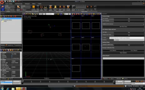
By turning on the Vicon switch, all cameras connect to the computer and the Blade software should be available for operation, Fig. 1. Before starting the operation, it is important to perform a check on the camera hardware settings and choose the recommended settings for the motion capture test. All the cameras must then be reset to these settings before use.
Fig. 1. Illustration of the Blade software start-up windows. After the program started-up, the connected camera’s light will blink and eventually the red circle on front of the camera will come on. This is a visual check to ensure all
2.1. 1. 3D space calibration
The 3D space calibration was performed using a T-shaped calibration wand to which 5 markers were attached. The wand was placed in the middle of the motion capture area, and then the calibration was started. In next step the wand was waved slowly around the room to define the general 3D space area. The wand then waved on closer to the floor area around the room to define the minimum 3D space area. Finally, the wand waved up and down to define the maximum 3D space area. After this step the wand was placed in the middle of the space, and the calibration process was stopped.
2.1. 2. Origin calibration
To define the origin, the wand was placed in the middle of the room. The wand’s handle was pointed toward the negative direction to define the directions of the X and Y axis. The software was then zoomed to locate all the cameras in the 3D space. The “Calibrate Origin” function was then performed and all cameras were adjusted above the floor plane.
2.1. 3. Floor plane calibration
To calibrate the floor plane, either the wand or markers can be used but placing markers around the floor gave a better representation of the lab floor since it is not as perfectly levelled as in the software domain. Five markers were placed on the floor space within the 3D space area. Then the floor plan calibration was carried out. After finishing the calibration process, an example was tested to make sure the device is perfectly working.
2.1. 4. Motion capture of the hip
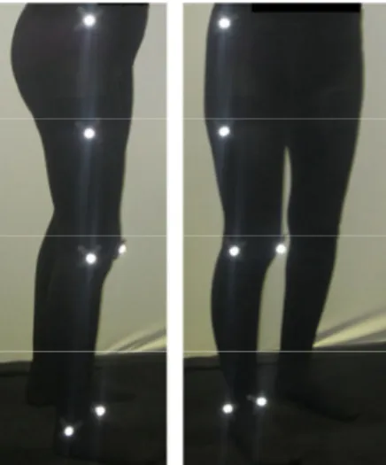
According to the anatomy palpation and surface markings, places of the marker were chosen on the skin [5,6]. Six markers, as shown in Fig. 2, were attached to the lower limb body to capture the motion of the hip. The location of each marker was recorded against time according to its coordinate in the 3D space which was already defined in the software.
Fig. 2. Six markers were attached to the lower limb body to capture the motion of hip.
The rotation of the hip was measured based on the flexion, adduction to the maximum range and internal rotation up to 90 degree of flexion. Fig. 3 shows the first step to measure the flexion of the hip. The position of the reference markers before and after flexion was measured. The flexion angle was calculated based on Equation (1).
Cos Į= ( |ba|2+ |ba`|2+ |aa`|2)/2 (|ba|)(|ba`|) (1) The flexion angle can be calculated by knowing the coordinate of markers at points b, a, a` and also the distances of |ba|, |ba`| and |aa`|.
Fig. 3. The marker b was the refrence marker and the position of marker a before and after full flexion was measured to find the flexion angle.
To measure the adduction, as it has been illustrated in Fig. 4, the leg of the subject volunteer was forced toward the centre of body. The markers positions before and after the movement was recorded. The adduction angle was calculated from the Equation (1).
Fig. 4. To measure the adduction the leg was forced toward the centre of body.
The same procedure as above mentioned for flexion was applied for internal rotation in 90° flexion. The leg was forced toward the center of body while it was at the hip and knee 90° flexion. The positions of the markers at the start and stop points of internal rotaton was recorded and the angle was calculated using the Equation (1).
2.2. Measurement using goniometer
The hip range of motion including flexion, adduction and internal rotation in 90°of flexion was measured by an adjustable goniometer for the subject volunteers. The data for the above motions was recorded for each of the volunteers and used to compare with the motion capture method.
2.2.1. Flexion
The subject volunteers were asked to bend their knee and bend their leg and bring it as close to their chest as is comfortable for them. The subject was then asked to lie supine in the anatomical position and in such a way that the
fulcrum is aligned with the greater trochanter of the femur. The measurement then took place by locating the stationary arm along the lateral midline of the abdomen, using the pelvis for reference and the moving arm of the goniometer was along the lateral midline of the femur.
2.2.2. Adduction
The subject volunteers were asked to move their leg to the inside toward their opposite leg. The subject was supine in anatomical position. The leg was measured when it was in full adduction. The fulcrum was placed in line with the anterior superior iliac spine and the moving arm was aligned with the midline of the patella.
2.2.3. Medial (internal) rotation
The subject brought their leg out to the side and then was asked to sit on the edge of the table, with their knees against the table, with their legs dangling down off the table. The fulcrum was aligned with the patella and both arms of the goniometer with the midline of the tibia. The stationary arm was then hanging freely but should be perpendicular to the floor.
3. Results and discussion
In this study the range of motion of three volunteers including flexion, adduction and internal rotation in 90°of flexion was measured using both the video tacking (motion capture) technique and the goniometer instrument. The range of motion of each volunteer was measured at least three times and the average result of each person was used for comparison. All volunteers were female age 28 years old with normal hips. The volunteers’ information including body mass index (BMI) is reported in Table 1 while the result from both motion capture and goniometer reported in Table2. The result of this study also compared with open literature in Table 2. There are no major differences between both motion capture and goniometer methods and the results are in agreement with previously
published results [14,15]. Furthermore, the standard deviation of repeatability of motion capture method was
relatively smaller than goniometer method which shows the video tracking method is more reliable to measure the ROM of the hip joint.
Table 1. Information of the three subject volunteers used in the experimental examination of this study
Subject volunteers Gender Age BMI( Kg/m2)
Volunteer 1 Female 28 18.37
Volunteer 2 Female 28 23.43
Volunteer 3 Female 28 29.14
Table 2. Comparing the end point result of both video tracking and goniometer measurement methods
Subject volunteers Motion capture Goniometer ROM in literature [14,15]
Flexion Volunteer 1 1200 1250 1030-1450 Volunteer 2 1100 1190 Volunteer 3 960 1050 Adduction Volunteer 1 500 600 40-520 Volunteer 2 550 480 Volunteer 3 510 470 Internal rotation Volunteer 1 310 400 110-610 Volunteer 2 270 350 Volunteer 3 280 340
4. Conclusion
The range of motion of three volunteers (including flexion, adduction and internal rotation in 90° of flexion) was measured using both motion capture and goniometer methods. The focus during motion of the hip joint was on the femoroacetabular impingement zone. The study measured the ROM of the hip joint at the end points using both methods, and no major differences between the results were found. Furthermore, the video tracking data displayed a minimum repeatability error in comparison with the goniometer technique.
Acknowledgements
The authors are grateful to the motion capture team at the Brunel University for providing facilities used to carry out the experimental research of this study.
References
[1] Charbonnier C., Assassi L., Volino P., Thalmann N., 2009. Motion study of hip joint in extreme postures, Visual Computer. 25 (9): 873-882. [2] Arokoski M.H., Haara M., Helminen H.J., Arokoski J.P., 2004. Physical function in men with and without hip osteoarthritis, Arch Phys Med
Rehabil. 85(4): 574-581.
[3] Holm I., Bolstad B., Lutken T., Ervik A., Rokkum M., Steen H., 2000. Reliability of goniometric measurements and visual estimates of hip ROM in patients with osteoarthrosis. Physiother Res Int 5(4): 241-248.
[4] Leunig M., Beaule P.E., Ganz R., 2009. The concept of femoroacetabular impingement: current status and future perspectives. Clin Orthop Relat Res. 467(3): 616-622.
[5] Tannast M., Kubiak-Langer M., Langlotz F., Puls M., Murphy S.B., Siebenrock K.A., 2007. Noninvasive three-dimensional assessment of femoroacetabular impingement, J Orthop Res. 25(1): 122-131.
[6] Bierma-Zeinstra S.M., Bohnen A.M., Ramlal R., Ridderikhoff J., Verhaar J.A., Prins A. 1998. Comparison between two devices for measuring hip joint motions, Clin Rehabil. 12(6): 497-505.
[7] Lea R.D., Gerhardt J.J., 1995. Range-of-motion measurements, J Bone Joint Surg Am. 77(5): 784-798.
[8] Allard P, Stokes IAF, Blanchi JP, 1995. Three-dimensional analysis of human movement, Champaign: Human Kinetics 1st edition. [9] Nussbaumer S., Leunig M., Glatthorn J. F., Stauffacher S., Gerber H., Maffiuletti N. A., 2010. Validity and test-retest reliability of manual
goniometers for measuring passive hip range of motion in femoroacetabular impingement patients, BMC Musculoskeletal Disorders. 11:194.
[10] Kennedy M.J., Lamontagne M., Beaule P.E., 2009. Femoroacetabular impingement alters hip and pelvic biomechanics during gait Walking biomechanics of FAI, Gait & Posture. 30: 41-44.
[11] Lamontagne M., Kennedy M.J., 2009. The Effect of Cam FAI on Hip and Pelvic Motion during Maximum Squat, Clin Orthop Relat Res. 467: 645-650.
[12] Della Croce U., Leardini A., Chiari L., Cappozzo A., 2005. Human movement analysis using stereophotogrammetry, Part 4: assessment of anatomical landmark misplacement and its effects on joint kinematics. Gait Posture. 21: 226-237.
[13] Leardini A., Chiari L., Della Croce U., Cappozzo A., 2005. Human movement analysis using stereophotogrammetry. Part 3. Soft tissue artifact assessment and compensation. Gait Posture. 21: 212-225.
[14] Reinschmidt C., van den Bogert A.J., Nigg B.M., Lundberg A., Murphy N., 1997. Effect of skin movement on the analysis of skeletal knee joint motion during running. J Biomech. 30: 729-732.
[15] Kubiak Langer M., Tannast M., Murphy S.B., Siebenrock K.A., Langlotz F., 2007. Range of Motion in Anterior Femoroacetabular Impingement, Clinical orthopaedics and related research, Number 458, pp. 117-124,
[16] Clohisy J.C., Knaus E.R., Hunt D.M., Lesher J.M., Harris-Hayes M., Prather H., 2009. Clinical Presentation of Patients with Symptomatic Anterior Hip Impingement, Clin Orthop Relat Res. 467(3): 638-644.