This is an Open Access document downloaded from ORCA, Cardiff University's institutional
repository: http://orca.cf.ac.uk/125710/
This is the author’s version of a work that was submitted to / accepted for publication.
Citation for final published version:
Kajati, Erik, Papcun, Peter, Liu, Chao, Zhong, Ray Y., Koziorek, Jiri and Zolotova, Iveta 2019.
Cloud based cyber-physical systems: Network evaluation study. Advanced Engineering Informatics
42 , 100988. 10.1016/j.aei.2019.100988 file
Publishers page: http://dx.doi.org/10.1016/j.aei.2019.100988
<http://dx.doi.org/10.1016/j.aei.2019.100988>
Please note:
Changes made as a result of publishing processes such as copy-editing, formatting and page
numbers may not be reflected in this version. For the definitive version of this publication, please
refer to the published source. You are advised to consult the publisher’s version if you wish to cite
this paper.
This version is being made available in accordance with publisher policies. See
http://orca.cf.ac.uk/policies.html for usage policies. Copyright and moral rights for publications
made available in ORCA are retained by the copyright holders.
Cloud Based Cyber-Physical Systems:
Network Evaluation Study
Erik Kajatia,∗, Peter Papcuna, Chao Liub, Ray Y. Zhongc, Jiri Koziorekd,
Iveta Zolotovaa
aDepartment of Cybernetics and Artificial Intelligence, Faculty of Electrical Engineering
and Informatics, Technical University of Kosice, Slovakia
b
High-Value Manufacturing Research Group, School of Engineering, Cardiff University, United Kingdom
c
Department of Industrial and Manufacturing Systems Engineering, The University of Hong Kong, Hong Kong
d
Department of Cybernetics and Biomedical Engineering, Faculty of Electrical Engineering and Computer Science, VSB - Technical University of Ostrava, Czech Republic
Abstract
In recent years, the Industry 4.0 concept brings new demands and trends in different areas; one of them is distributing computational power to the cloud. This concept also introduced the Reference Architectural Model for Industry 4.0 (RAMI 4.0). The efficiency of data communications within the RAMI 4.0 model is a critical issue. Aiming to evaluate the efficiency of data communication in the Cloud Based Cyber-Physical Systems (CB-CPS), this study analyzes the periods and data amount required to communicate with individual hierarchy levels of the RAMI 4.0 model. The evaluation of the network properties of the communication protocols eligible for CB-CPS is presented. The network properties to different cloud providers and data centers’ locations have been measured and interpreted. To test the findings, an architecture for cloud control of laboratory model was proposed. It was found that the time of the day; the day of the week; and data center utilization have a negligible impact on latency. The most significant impact lies in the data center distance and the speed of the
∗Corresponding author
Email addresses: [email protected](Erik Kajati),[email protected](Peter Papcun),[email protected](Chao Liu),[email protected](Ray Y. Zhong), [email protected](Jiri Koziorek),[email protected](Iveta Zolotova)
communication channel. Moreover, the communication protocol also has impact on the latency. The feasibility of controlling each level of RAMI 4.0 through cloud services was investigated. Experimental results showed that control is possible in many solutions, but these solutions mostly can not depend just on cloud services. The intelligence on the edge of the network will play a significant role. The main contribution is a thorough evaluation of different cloud providers, locations, and communication protocols to provide recommendations sufficient for different levels of the RAMI 4.0 architecture.
Keywords: Cloud, Cyber-Physical Systems, Industry 4.0, Microsoft Azure, Network evaluation, RAMI 4.0
1. Introduction
Industry 4.0 facilitates the vision and execution of a Smart Factory. Within the modular structured Smart Factories, Cyber-Physical Systems (CPS) monitor physical processes, create a virtual copy of the physical world and make decentralized decisions. Over the Internet of Things (IoT), CPS
5
communicate and cooperate with each other and with humans in real time, and via the Internet of Services, both internal and cross-organizational services are offered and utilized by participants of the value chain [1].
There are four design principles in Industry 4.0 that support companies in identifying and implementing Industry 4.0 scenarios [2]: interoperability;
10
information transparency; technical assistance; decentralized decisions.
Cloud computing, also known as on-demand computing, is a kind of Internet-based computing that provides shared processing resources and data to computers and other devices on demand. It is a model for enabling ubiquitous, on-demand access to a shared pool of configurable computing
15
resources (e.g., networks, servers, storage, applications, and services), which can be rapidly provisioned and released with minimal management effort. Cloud computing and storage solutions provide users and enterprises with various capabilities to store and process their data in third-party data centers
[3].
20
The Industrial Internet of Things (IIoT) is part of the IoT concept. IIoT solution is created when IoT principles are applied to the manufacturing industry. IIoT has been heralded primarily as a way to improve operational efficiency. However, in todays environment, companies can also benefit greatly from seeing it as a tool for finding growth in unexpected opportunities. In the
25
future, successful companies will use the IIoT to capture new growth through three approaches: boost revenues by increasing production and creating new hybrid business models, exploit intelligent technologies to fuel innovation, and transform their workforce [4].
The Platform Industrie 4.0 introduced the Reference Architectural Model
30
for Industry 4.0 (RAMI 4.0) which merges industry hierarchy levels architecture (ANSI/ISA 95), life cycle value stream architecture, and Smart Industry/Industry 4.0 ideas (Fig. 1). RAMI 4.0 is a three-dimensional map showing how to approach the issue of Industrie 4.0 in a structured manner, it also combines all elements and IT components in a layer and life cycle model.
35
[5]
The efficiency of data communications within the RAMI 4.0 model is a critical issue that significantly affects the performance of the whole system. Aiming to evaluate the efficiency of data communication in the Cloud Based Cyber-Physical Systems (CB-CPS), this study analyzes the time periods and
40
data amount required to communicate with individual hierarchy levels of the RAMI 4.0 model, from product to enterprise level. It is noted that the data amount and latency requirements for each level are different regarding their specific requirements. The higher levels exchange more data less frequently; on the contrary, the lower levels require faster communication with less data
45
amount. In addition, the individual levels also communicate with each other to exchange information through the hierarchy levels. The specific requirements of each individual level are summarized as follows:
• Enterprise level (ERP - Enterprise Resource Planning) offers production planning, service delivery, marketing and sales, financial modules, retail,
50
and support algorithms for decision making. Analyses of big amounts of data (from megabytes to terabytes) need to be performed in this level, and hence the time periods are usually higher than several minutes. • Work Centers level (MES - Manufacturing Execution System) includes
warehouse management, quality management, production records, repair
55
management and prevention, and operational planning. This level usually transfers tens of megabytes of data; while the time periods are from seconds to minutes.
• Stations level contains Supervisory Control and Data Acquisition (SCADA) and Human-Machine Interfaces (HMI). Data amounts are
60
from kilobytes to megabytes; while time periods are usually from tens of milliseconds to less than one second.
• Control Device level includes devices such as Programmable Logic Controllers (PLC) and industrial computers. Data amounts are from bytes to kilobytes and time periods are from microseconds to seconds.
• Field Device level includes sensors and actuators. Data amounts are from bytes to kilobytes and time periods are from microseconds to seconds. The industry has been gradually distributing computational power to the cloud, though the progress was slow due to security concerns. At the early stage, the top-level information systems have been migrated to the cloud, examples
70
being the SAP HANA, Wonderware MES, etc. Recently, in light of the Industry 4.0, there is a trend to migrate the SCADA systems and HMIs to the cloud, in case they do not require responses faster than 500ms.
When the user turns on the switch, delay should not be greater than 100ms to provide fluid reactions. In case of Augmented Reality-based HMIs, the
75
reaction of the HMIs should be around 40ms to maintain at least 25 frames per second refresh rate. Otherwise, the projected images would not look continuous. Other systems, like AC motors need control period in microseconds. Nowadays, migration of some control devices to the cloud is not possible, but some systems have slow dynamics, and they can be controlled
80
through cloud, as is described in this article. In some cases, all levels of RAMI 4.0, from Control Device level to Enterprise level, can be migrated to the cloud, and this creates the CB-CPS.
The rest of this paper is organized as follows. Section 2 presents the literature review. Section 3 deals with network evaluation using different
85
protocols and locations that can be used for the Control Device level of the RAMI 4.0 architecture. Section 4 evaluates system control on the laboratory model. Conclusions and future work are drawn in Section 5.
2. Literature review
In recent years, the Industry 4.0 concept brings new demands and trends in
90
different areas. Machine tools are changing in this industrial revolution and have also gone through different stages of technological advancements [6]. Cyber-Physical Machine Tools (CPMT) provides a promising solution for Machine Tool 4.0 a new generation of machine tools. Liu et al. [7], [8]
proposed a generic system architecture to provide guidelines for advancing
95
existing Computer Numerical Control (CNC) machine tools to CPMT. The processes require more and more computational power. The end devices can offer some of the computational power, but these devices often do not meet the requirements for the computationally demanding processes. These processes may include running algorithms of the computer vision, machine
100
learning, or data analytics [9], [10]. With the rapid development of computer networks and Internet connections anywhere in the world, there is an opportunity to offload some of the computationally demanding algorithms to the cloud from the end devices.
Cloud and CPS are connected through the network, which forms the
105
Networked Control System (NCS). NCS is the control system in which the components including controller, sensors, actuators and other system components exchange the information using a shared media or network [11]. The development of NCS has been running for several decades. At the early stage, it was solved within the LAN networks of companies. The results of the
110
mentioned research and development are deterministic industrial real-time networks, such as ProfiNet, Ethernet/IP and EtherCAT. Nowadays, research is moving further towards studying whether NCS can move beyond the boundaries of companies to the cloud.
Givehchi et al. [12] presented a cloud-based solution that aims at offering
115
control-as-a-service for an industrial automation case (see Figure 2). According to the authors, the PLC could not only remain in the shop floor as a physical device, but also be implemented as a virtual entity and delivered to the field as a service from a CPS via the network. Network rules and policies such as access permissions for virtual machines defined for the cloud will be applied by
120
virtual switch (vSwitch) which is managed by vCloud Networking and Security component using VMwares vCloud suite, which is connected to the Profinet Real-Time Ethernet system (RT) via physical interface.
Their results showed that there is a reduction of performance for cloud-based scenario compared with a hardware PLC. This reduction in performance
Figure 2: A generic cloud-based control approach [12].
is mostly in systems with higher sampling rates (32ms and faster). In processes that require sampling rate 64ms and slower, the difference between a cloud-based scenario and the hardware PLC is lower and mostly negligible, but it also depends on the type of the application. Hence, their solution is promising for soft real-time applications.
130
Schlechtendahl et al. [13] conducted two use cases of cloud-based control system using two milling machines. The data transferred between the control system and the machine tools have been analyzed. Then the data was used to analyze if a Control System as a Service (CSaaS) is possible. A communication test setup was developed as shown in Figure 3.
135
The cloud communication module located in Stuttgart, Germany, creates the data that is transferred from the cloud to the machine. The machine communication module, which receives the data from Stuttgart, is located either in Auckland, New Zealand or in Google cloud center located in Europe.
Figure 3: Test setup communication [13].
The machine communication module receives and logs the data, and as a
140
second step creates and transmits the data from the machine to the cloud system. Communication channels can be configured for different connection protocols - User Data Protocol (UDP), Transmission Control Protocol (TCP) and WebSocket Protocol. The authors conclude that CSaaS between New Zealand and Germany is not possible due to serious network challenges. The
145
control system should be located closer to the machine. CSaaS between the Google Cloud Centre in Europe and Germany is possible for processes that require slow cycle times [13].
According to Givehchiet al. [12], control of systems with sampling rate 64ms and slower can be cloud-based and differences between the hardware PLC and
150
cloud-based scenarios are mostly negligible. Schlechtendahlet al. [13] concluded that CSaaS for processes that require slow cycle times is possible if the machine and cloud center are on the same continent.
Nowadays, a considerable amount of research works have been conducted on cloud-based access to devices through different protocols [14], [15] and
155
frameworks [16]. Many researchers are working on the migration of low-level control to the cloud [12], [13], [17]. Furthermore, research has been conducted on the migration of high-level control to the cloud, concretely ERP, or MES systems [18], [19], [20]. In effect, most of the previous research works were dedicated to a certain level of RAMI 4.0. The lack of an overview of the
control in all levels of RAMI 4.0 represents the first research gap. This paper provides a broader view on which levels of the RAMI 4.0 can be migrated with specified conditions to the cloud. Details of this issue are discussed in the third chapterNetwork evaluation.
Research on the Quality of Control (QoC) via local NCS has also been
165
investigated for several years (e.g. [21]). However, QoC via cloud NCS still remains an unresolved issue, which represents the second research gap. In this work, a laboratory model with sampling time 100ms and several cloud providers is developed to 1) demonstrate the proposed CB-CPS architecture, 2) verify the feasibility of the CSaaS, and 3) evaluate the QoC via cloud NCS. The fourth
170
chapterNetworked control system evaluation introduces the development and the experimental results of the laboratory model.
3. Network evaluation
The experimental results of this research are analysed from two aspects in two sections, respectively. This section deals with network properties using
175
different protocols and control options. The following section evaluates system control using a different approach. If the control algorithm is migrated to the cloud, then the NCS is formed in large scale, where the PLC is replaced with the cloud. NCS is a control system where the control loops are closed through a communication network.
180
To be able to evaluate the properties of the network, the theoretical and physical limitations need to be identified first. The fastest communication medium available is an optical fiber. If two outermost places in the world can be connected without intermediate network devices (switches, routers, repeaters), the theoretical latency is 134ms, as calculated in (1).
185 L= 2 C 2 c = 40075km 299792km/s= 134ms (1)
Two outermost places are C
2 apart (C is Earth’s circumference), in reality,
sending and returning a packet, so the packet must pass that distance two times (2C
2). Parametercis the speed of light and parameterLis latency. Real latency
can be reduced by technological progress, but cannot reach below the theoretical
190
minimum. This implies that if the speed of light is the highest achievable speed, it will never be possible to control the system with sampling period lower than 134ms from two outermost places on Earth without using additional algorithms (for example, prediction algorithm).
In this research, the latency for the three most commonly used cloud
195
providers, i.e. Amazon Web Services, Google Cloud Platform and Microsoft Azure is analyzed. Data centers located in west Europe (WestEU), east United States (EastUS), and eastern Australia (EastAU) were chosen. The air fly distance to data centers in WestEU is approx. 1 300km (theoretical minimum according to (1) is 9ms); the distance to data center in EastUS is
200
approx. 9 000 km (theoretical minimum according to (1) is 60ms); and the distance to data center in EastAU is approx. 15 000km away (theoretical minimum according to (1) is 100ms). The data center in Europe represents the fastest/closest data center. The data center in the United States represents the intercontinental communication. The data center in Australia
205
will provide communication with the outermost data center. Multiple measurements were made at different times of the day and for every day of the week during February 2019 from Technical University of Kosice, Slovakia. Specifically, measurements were made 1000 times every 2 hours from 1st February at 12 am to 28th February at 10 pm, that is 336.000 measurements.
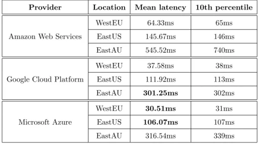
210
Experimental results of the mean latency and the 10th percentile (90% of the values are better) are summarized in Table 1.
Based on the results from Table 1, the Microsoft Azure cloud platform has been chosen for this study. It is found that Microsoft Azure has the lowest latency for the EastUS and WestEU from the three, although Google Cloud
215
Platform has a slight better performance for the EastAU. For the laboratory testing model used in this research, the most important locations are those with a latency below or around 100ms. The reason for including EastAU in this
Table 1: Latency between east Slovakia and cloud providers’ data centers. Provider Location Mean latency 10th percentile
Amazon Web Services
WestEU 64.33ms 65ms
EastUS 145.67ms 146ms
EastAU 545.52ms 740ms
Google Cloud Platform
WestEU 37.58ms 38ms EastUS 111.92ms 113ms EastAU 301.25ms 302ms Microsoft Azure WestEU 30.51ms 31ms EastUS 106.07ms 107ms EastAU 316.54ms 339ms
research is to test the communication with the location that is the farthest from the location of the laboratory model, i.e. Slovakia.
220
After chosen the Microsoft Azure as the cloud provider, the communication protocols need to be selected and analyzed. In this research, the following four communication protocols were selected:
• HTTP - Hypertext Transfer Protocol - commonly used protocol for communication between server and clients [22].
225
• WCF - Windows Communication Foundation service - a framework for building service-oriented applications [23]. WCF Web HTTP service was chosen for measurements.
• OPC UA - Open Platform Communication Unified Architecture - a machine to machine communication protocol for industrial automation
230
[24].
• AMQP - Advanced Message Queuing Protocol - publish-subscribe-based messaging protocol, commonly used in IoT solutions [25].
every day of the week during March 2019 from Technical University of Kosice,
235
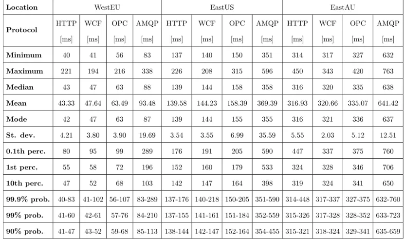
Slovakia. Specifically, measurements were made 1000 times every 2 hours from 1st March at 12 am to 31st March at 10 pm for all communication protocols, that is 1.488.000 measurements. It is found that the time of the day and the day of the week have a negligible impact on the latency. Therefore, the table is not divided by the time of the measurement. The experimental results are
240
summarized and analyzed in Table 2. The minimum and maximum latency, the median, mean, mode, and standard deviation for each protocol have been summarized. Three percentile values (0.1th, 1st, 10th) which indicate 99.9%, 99%, and 90% of values that are better than the corresponding value are also summarized in the table. The last three rows indicate the smallest interval in
245
which the value will be with 99.9%, 99%, and 90% probability.
As shown in Table 2, HTTP is the fastest communication protocol among the four protocols, at all data centers locations. The overall order of the communication protocols, based on the latency, grouped by the location are the same for all locations. That means, data center utilization has minimal
250
effect on the latency; the most significant impact is on the distance to the data center and the speed of the communication channel.
For a better representation of some statistical results, a box plot is made to display the distribution of the latency values (Figure 4).
It can be seen from Table 2 and Figure 4 that the results from HTTP,
255
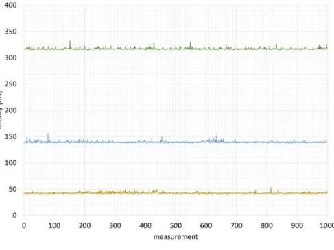
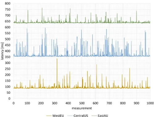
WCF and OPC UA are less scattered than that from AMQP communication. Moreover, results from HTTP and WCF are very similar in all locations; OPC UA is just slightly slower than the two mentioned. On the contrary, AMQP communication is a lot slower compared to the other three; also the dispersion of the values is a lot wider. To better understand the consistency of the latency
260
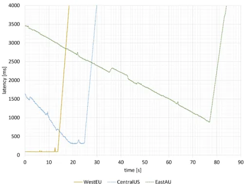
measurements, 1000 values (period: one message per second) of HTTP and AMQP communication are selected and displayed in Figure 5 and Figure 6, respectively.
The lower tier of the IoT Hub service, which was used for testing, allowed 100 cloud-to-device messages/unit/minute. When 100 messages were sent in
Table 2: Cloud control communication protocols evaluation.
Location WestEU EastUS EastAU
Protocol HTTP [ms] WCF [ms] OPC [ms] AMQP [ms] HTTP [ms] WCF [ms] OPC [ms] AMQP [ms] HTTP [ms] WCF [ms] OPC [ms] AMQP [ms] Minimum 40 41 56 83 137 140 150 351 314 317 327 632 Maximum 221 194 216 338 226 208 315 596 450 343 420 763 Median 43 47 63 88 139 144 158 358 316 320 335 638 Mean 43.33 47.64 63.49 93.48 139.58 144.23 158.39 369.39 316.93 320.66 335.07 641.42 Mode 42 47 63 87 139 144 155 355 316 321 336 637 St. dev. 4.21 3.80 3.90 19.69 3.54 3.55 6.99 35.59 5.55 2.03 5.12 12.51 0.1th perc. 80 95 99 289 176 191 205 590 447 337 375 760 1st perc. 55 58 72 196 152 160 179 533 324 328 346 706 10th perc. 47 52 68 103 142 147 164 398 319 324 341 650 99.9% prob. 40-83 41-102 56-107 83-289 137-176 140-218 150-205 351-590 314-448 317-337 327-375 632-760 99% prob. 41-60 42-61 57-76 84-210 137-155 141-161 151-184 352-559 315-326 317-328 328-352 633-723 90% prob. 41-47 43-52 59-68 85-113 138-144 142-147 152-164 354-455 315-321 318-324 329-341 635-659 13
Figure 4: Distribution of the latency values grouped by location.
one minute interval, throttling was applied. Theoretically, the IoT Hub should be able to communicate at full speed for the first 10 seconds. However, it was noticed that it always took 3 to 5 seconds after reaching the limit of 1000 messages per minute until throttling was applied. At EastUS and EastAU locations, throttling was applied after a longer time interval. This was caused
270
by the longer intervals between messages from the cloud to the device. Even if the requests were sent every 1ms, the average shortest interval was 150ms between responses from EastUS, and 320ms from EastAU (Figure 7). The top tier edition type of the IoT Hub can send as many as 5000 cloud-to-device messages/unit/minute, but it costs several thousands of euros per unit.
275
If the latency was known, it is able to analyze which communication protocols can be applied to the individual levels of the RAMI 4.0. Since the Station level mostly requires communication under one second, all of the tested protocols could meet this criterion, even the most distant location (EastAU) and the
Figure 5: Consistency of the latency measurements - HTTP.
slowest protocol (AMQP) is sufficient, with 99.9% of the latency values under
280
760ms. Higher levels (Work Centers, Enterprise) have lower demands on latency, but they have higher requirements on the data transfer speeds. Therefore, all higher hierarchy levels (Station, Work Centers, Enterprise) of RAMI 4.0 can be controlled and executed through cloud services as long as the data transfer speeds are sufficient.
285
Since time periods required for the Control device level in RAMI 4.0 are from microseconds to seconds, we have split these periods into three main categories as follows:
• more than 1s – heating, ventilation, and air conditioning, • 1s to 40 ms – lights, switches, relays,
290
Figure 6: Consistency of the latency measurements - AMQP.
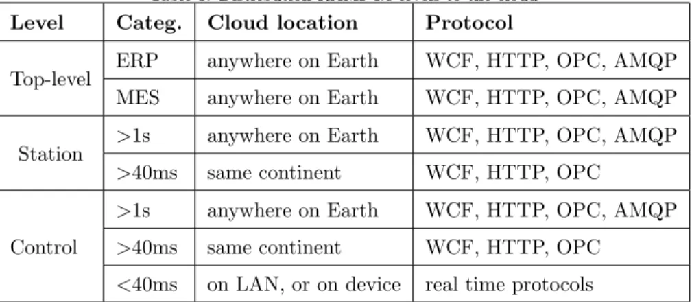
As described in Table 3, technological processes which do not require latency/control period lower than 1s, can be controlled through cloud services without dependencies on the type of communication service or the data centers’ location. Moreover, a conclusion is summarized from our testing:
295
processes that require latency/control period lower than 40ms cannot be controlled through cloud services. The third group of technological processes which require times between 1s and 40ms is dependent on the communication protocol and location of the cloud data center, or the speed of the communication channel between physical processes and data centers’ location.
300
The latency is subject to communication channel usage, not just the distance between communicating nodes; sometimes the faster channel could be the a more distant one. In this analysis, the computational complexity has been neglected at each RAMI4.0 level, because the cloud is highly scalable, and complex algorithms can be solved with hundreds or thousands of CPU cores in
Figure 7: IoT Hub throttling.
one millisecond.
Based on all the aforementioned findings, we have decided to implement control algorithm for the laboratory model with all of the four communication protocols at WestEU location. These protocols could meet our requirement of 100ms latency. The success of the IoT Hub service depends on the duration of
310
the regulation; while the other three protocols (WCF, HTTP and OPC UA) should be able to fulfill our regulation aims.
4. Networked Control System Evaluation
A laboratory model is developed to test the proposed CB-CPS architecture (Figure 8). The laboratory model works with the sampling time 100ms;
315
therefore it does not require hard real-time control. This model was chosen because it can represent any industrial system with relatively slow dynamics
Table 3: Distribution RAMI 4.0 levels to the cloud Level Categ. Cloud location Protocol
Top-level ERP anywhere on Earth WCF, HTTP, OPC, AMQP
MES anywhere on Earth WCF, HTTP, OPC, AMQP
Station >1s anywhere on Earth WCF, HTTP, OPC, AMQP
>40ms same continent WCF, HTTP, OPC
Control
>1s anywhere on Earth WCF, HTTP, OPC, AMQP
>40ms same continent WCF, HTTP, OPC
<40ms on LAN, or on device real time protocols
(e.g. crane hook, path planning, etc.). The system is controlled by a PLC which is connected to the local computer in the laboratory through OPC DA connection. The model can be controlled both locally with PLC controller and
320
remotely from the cloud with cloud services.
Figure 8: Proposed architecture for cloud control.
The laboratory model Traverse (Figure 9) is located in a laboratory at the Department of Cybernetics and Artificial Intelligence, Faculty of Electrical Engineering and Informatics at Technical University of Kosice.
Figure 9: Laboratory model Traverse.
The controlled agent offers a regulation of a ball on an inclined surface.
325
The inclined surface consists of two cylinders that are connected to the wooden construction of the bridge (Figure 10). The length of the bridge is 67cm and the diameter of the ball is 10cm. Thus, the total length of the path that the ball can travel is 57cm from end to end. This bridge is suspended on two steel cables connected to the axles of two asynchronous motors with an
electro-330
mechanic brake and incremental rotary encoders. Axle rotation of the left or the right motor is transformed to the height change of the left or right end of the bridge. The motors are controlled with two frequency converters. These frequency converters are controlled by an analog signal from the PLC.
Position sensing of the ball is provided by the two cylinders that support ball.
335
One of the cylinders is made from brass, and the other is wrapped in copper wire. These cylinders use the principles of rheostat to transform the physical position of the ball to the voltage signal. This voltage signal is connected to the analog voltage input of the PLC.
Despite its specific functions, this model can represent various kinds of agents
340
in an industrial system. One example is the industrial control systems. If there is more than one agent in the system, it becomes a multi-agent system where agents can collaborate or cooperate with each other.
This solution is an example of using cloud systems in the technological level of control. Our solution tests the control algorithms implemented on a
345
cloud and proposes an architecture for the communication with the cloud. This architecture can be used to migrate parts of the algorithms, that demand high computing power, to the cloud. For example, processes of control that use image recognition, neural networks and machine learning. To examine control with the cloud technology, a PID algorithm was applied. This case
350
study compares local PID control and cloud-based PID control. In future research and development, control algorithm with image recognition could also be migrated to the cloud, based on proposed architecture.
Initially, the model Traverse has to be identified for the synthesis of the PID controller. The equation (2) represents the kinematic model of the ball motion.
355
s=1 2gt
2
I(sin(α)−fdcos(α)) (2) Wheresis the length of the path travelled by the ball in timet,gis gravity acceleration, I represent torque of the ball, α is the inclination of the bridge measured in degrees. Parameter fd is the coefficient of rolling friction of the ball that is quite high, due to the fact, that ball is tightly fitted between the two cylinders. The coefficient of rolling friction was measured experimentally.
360
FS(s) =
1,422s2+ 6,547s+ 24,674
s3 (3)
The PID controller was applied in classical closed-loop feedback control (Figure 11), wherew(t) is desired value,e(t) is regulation error,u(t) is system input, and y(t) system output. PID control algorithm coefficients were then tested in the closed-loop system within software Matlab/Simulink with
365
positive results for multiple desired output values.
Figure 11: Feedback control scheme.
For the cloud-based control, a program with a graphical interface was created. The program was developed with the use of Microsoft Visual Studio 2017 development environment. The program works with 100ms sampling period. In every step, the actual position of the ball is downloaded from the
370
PLC. This data is sent to the cloud, where the control algorithm is implemented. Then the computed control values are sent back from the cloud. After the program receives the control value from the cloud, the value is sent back to the PLC.
In this work, the response of the system for different desired values have been
375
tested. These values represent the movement from the left side of the bridge to the desired value, represented by the percentage of the total length of the bridge. At the beginning of the measurement, the ball was always positioned at the left end of the bridge (refer to Figure 10). The left end of the bridge represents the position of 0%. In each test, the desired position was set at the
380
beginning of the measurement.
Figure 12 shows the comparison of local and cloud control from 0% (left side of the bridge) to the 20% position. Under the cloud control, the ball position
progresses are similar for all four communication protocols; and the regulations were all finished between 5th and 6th second. Whereas under the local control
385
algorithm, the regulation was finished in less than 3 seconds.
Figure 13 shows the comparison of local and cloud control from 0% to the 60% position. It can be seen that the ball position progresses are even more similar than in the previous regulation, but it took longer to get the ball to the desired position. For all four communication protocols, it took between 7 and
390
9 seconds to finish regulation. Again, local control was slightly faster, with a regulation time equal to 6 seconds.
These experimental results proved that the developed system can be successfully controlled through cloud services in which the latency is under 100ms. Even IoT Hub got the ball to the desired position because the
395
regulation was short and throttling was not applied. Mean latency for all tested communication protocols was under 100ms in EastEU location. The 99.9% of all measured latency values of HTTP, WCF, and OPC UA protocols were also under 100ms. In the case of IoT Hub, this number was higher, only 90% probability that the latency is under 103ms, but it was still sufficient for
400
the regulation.
Driven by these positive results, the cloud control was further implemented through the EastUS data center. Figure 14 shows the comparison of cloud control protocols from position 0% to 20%. It can be concluded from the figure that HTTP communication (mean latency: 139ms, 99% of latency values are
405
under 152ms) can successfully control the ball to the desired position, although the progress has more oscillations. WCF protocol (mean latency: 144ms, 99% of values are under 160ms) can not control the model, and the ball is oscillating around the desired position. OPC UA protocol (mean latency: 158ms, 90% of values are under 179ms) can not control the model; the ball oscillates with an
410
increasing amplitude. The results of AMQP testing through EastUS location (mean latency: 370ms, 99% of values are under 533ms) were not included in the figure, since after multiple tests it was found that the ball was just bouncing from the one side of the bridge to the other at high speeds, so we decided to
Figure 12: Comparison of local and cloud algorithms, w=20%.
exclude AMQP protocol from this testing.
415
5. Conclusions and future work
In conclusion, the aim of this paper was to evaluate the network properties of the communication protocols eligible for the proposed CB-CPS. The main contribution is a thorough evaluation of different cloud providers, locations, and communication protocols to form recommendations sufficient for the
cloud-420
based control in different levels of the RAMI 4.0 architecture. Relevant works conducted by other researchers have been reviewed. The RAMI 4.0 architecture has been analyzed with a focus on the control in each level. Various types of network measurements have been conducted based on our findings.
The network properties of three most commonly used cloud providers
425
Figure 13: Comparison of local and cloud algorithms, w=60%.
been evaluated. For all three providers, the latency to data centers in three different locations (west Europe, east United States, and eastern Australia) were tested. Based on the test results, Microsoft Azure cloud services was chosen for further study . Four different communication protocols (HTTP,
430
WCF, OPC UA, and AMQP) were implemented and the latency of all protocols were analyzed and compared. All the measurements were made throughout the whole week at different times of the day.
All the experimental results have been recorded and analyzed in tables and figures. It was found that the time of the day and also the day of the week have
435
a negligible impact on latency. HTTP was the fastest communication protocol among the four protocols, at all data centers locations. The overall order of the communication protocols, based on the latency, grouped by the location is the same for all locations. That means, data center utilization has minimal effect on the latency; the most significant impact is on the distance to the data
Figure 14: Comparison of cloud algorithms, w=20%.
center and the speed of the communication channel. Results of HTTP and WCF were very similar in all locations; OPC UA is just slightly slower than the two mentioned. On the contrary, AMQP communication is a lot slower compared to the remaining three; also the dispersion of the values is a lot wider.
To prove that control can be done from the cloud services we have
445
implemented a control algorithm through different communication protocols and data centers locations. It was found that communication protocols latency implemented in west Europe data centers are sufficient to control our laboratory model. At the east United States, the situation was different; only the fastest protocol (HTTP) was able to control the model successfully.
450
Therefore, the latency limit for successful control is concluded to be around 139ms (also, at least 99% of values should be under 152ms).
Cloud requirements of the Station level of the RAMI 4.0 architecture and latency and data amount requirements of the other RAMI 4.0 hierarchy levels
have been analyzed. The feasibility of controlling each level of RAMI 4.0 though
455
cloud services were investigated. Experimental resutls showed that control is possible in many solutions, but these solutions will not be depending just on the cloud services. The intelligence on the edge of the network will play a significant role [26]. The computing capacities of end devices are increasing; fog/edge computing will shift intelligence closer to systems which will reduce
460
the amount of data that need to be transferred as well as shorten the latency. It is worth mentioning that all these changes should be made with the needs of the human in mind. In the time of automation and significant technological innovations, there is a growing uncertainty about the role of humans in the industry. Operators in the future will need to have a broader set of skills because
465
they will be working with the high-end HMI devices [27]. Therefore, there is an urgent need to assess human factor in the frame of cyber-physical systems via human-in-the-loop cyber-physical systems [28].
Moreover, cloud-based SCADA systems [29] as described in [30] is another future research direction. In the future, a combination of these architectures
470
into one functional system will be developed. Our future work will focus on the development and implementation of more distributed computational power, not just towards the cloud, but also to the edge of the network – edge computing.
Acknowledgements
This publication was supported by the grant VEGA - 1/0663/17
475
Intelligent Cyber-Physical Systems in Heterogeneous Environment Supported by IoE and Cloud Services. This work was supported by the European Regional Development Fund in the Research Centre of Advanced Mechatronic Systems project, project number CZ.02.1.01/0.0/0.0/16 019/0000867 within the Operational Programme Research, Development and Education.
480
Declarations of interest
References
[1] P. Marcon, F. Zezulka, I. Vesely, Z. Szabo, Z. Roubal, . Sajdl, E. Gescheidtova, P. Dohnal, Communication technology for industry 4.0, in:
485
2017 Progress In Electromagnetics Research Symposium - Spring (PIERS), 2017, pp. 1694–1697. doi:10.1109/PIERS.2017.8262021.
[2] M. Hermann, T. Pentek, B. Otto, Design principles for industrie 4.0 scenarios, in: 2016 49th Hawaii international conference on system sciences (HICSS), IEEE, 2016, pp. 3928–3937. doi:10.1109/HICSS.2016.488.
490
[3] Q. F. Hassan, Demystifying cloud computing, CrossTalk: The Journal of Defense Software Engineering 24 (2011) 16–21.
[4] R. Pethuru, R. Anupama, The Internet of Things: Enabling Technologies, Platforms, and Use Cases, CRC Press, 2017.
[5] K. Schweichhart, Reference architectural model industrie 4.0 (rami 4.0)
495
- an introduction, Standardization & Reference Architecture - Plattform Industrie 4.0, 2015.
[6] X. Xu, Machine tool 4.0 for the new era of manufacturing, The International Journal of Advanced Manufacturing Technology 92 (5-8) (2017) 1893–1900. doi:10.1007/s00170-017-0300-7.
500
[7] C. Liu, H. Vengayil, R. Zhong, X. Xu, A systematic development method for cyber-physical machine tools, Journal of Manufacturing Systems (2018) 1–12doi:10.1016/j.jmsy.2018.02.001.
[8] C. Liu, H. Vengayil, Y. Lu, X. Xu, A cyber-physical machine tools platform using opc ua and mtconnect, Journal of Manufacturing Systems 51 (2019)
505
61–74.
[9] R. Zhong, C. Xu, C. Chen, G. Huang, Big data analytics for physical internet-based intelligent manufacturing shop floors, International Journal
of Production Research (2015) 2610–2621doi:10.1080/00207543.2015. 1086037.
510
[10] C. Deng, R. Guo, C. Liu, R. Y. Zhong, X. Xu, Data cleansing for energy-saving: a case of cyber-physical machine tools health monitoring system, International Journal of Production Research 56 (1-2) (2018) 1000–1015. [11] R. A. Gupta, M. Chow, Networked control system: Overview and research
trends, IEEE Transactions on Industrial Electronics 57 (7) (2010) 2527–
515
2535. doi:10.1109/TIE.2009.2035462.
[12] O. Givehchi, J. Imtiaz, H. Trsek, J. Jasperneite, Control-as-a-service from the cloud: A case study for using virtualized plcs, IEEE International Workshop on Factory Communication Systems - Proceedings, WFCS (2014) 1–4doi:10.1109/WFCS.2014.6837587.
520
[13] J. Schlechtendahl, F. Kretschmer, Z. Sang, A. Lechler, X. Xu, Extended study of network capability for cloud based control systems, Robotics and Computer-Integrated Manufacturing 43 (2017) 89–95. doi:10.1016/j. rcim.2015.10.012.
[14] P. Masek, R. Fujdiak, K. Zeman, J. Hosek, A. Muthanna, Remote
525
networking technology for iot: Cloud-based access for alljoyn-enabled devices, in: Proceedings of the 18th Conference of Open Innovations Association FRUCT, FRUCT Oy, 2016, pp. 200–205.
[15] F. Zezulka, P. Marcon, Z. Bradac, J. Arm, T. Benesl, I. Vesely, Communication systems for industry 4.0 and the iiot, IFAC-PapersOnLine
530
51 (6) (2018) 150–155.
[16] K. Sladka, M. Babiuch, Application of control algorithms in. net micro framework technology, in: 2016 17th International Carpathian Control Conference (ICCC), IEEE, 2016, pp. 684–687.
[17] J. Schlechtendahl, F. Kretschmer, A. Lechler, V. A, Communication
535
in Manufacturing. Proceedings of the 47th CIRP Conference on Manufacturing Systems, 2014, pp. 830–834. doi:10.1016/j.procir. 2014.01.074.
[18] L. Hurbean, D. Fotache, Erp iii the promise of a new generation, in:
540
The 13th International Conference on Informatics in Economy, Education, Research & Business Technologies, 2014, pp. 1–5. doi:10.13140/2.1. 3906.1765.
[19] J. Vasilev, The change from erp ii to erp iii systems, in: 3rd International Confernece on Application of Information and Communication Technology
545
and Statistics in Economy and Education (ICAICTSEE 2013), 2013, pp. 1–3. doi:10.13140/2.1.5109.7609.
[20] P. Helo, M. Suorsa, Y. Hao, P. Anussornnitisarn, Toward a cloud-based manufacturing execution system for distributed manufacturing, Computers in Industry 65 (4) (2014) 646 – 656. doi:10.1016/j.compind.2014.01.
550
015.
[21] K. Ji, W. J. Kim, Real-time control of networked control systems via ethernet, International Journal of Control, Automation and Systems 3 (4) (2005) 591–600.
[22] W3Schools, Hyper text transfer protocol, https://www.w3schools.com/
555
whatis/whatis_http.asp.
[23] Microsoft, Windows communication foundation, https://docs. microsoft.com/en-us/dotnet/framework/wcf/whats-wcf.
[24] OPC Foundation, Windows communication foundation, https:// opcfoundation.org/about/opc-technologies/opc-ua/.
560
[25] ISO/IEC 19464, Advanced message queuing protocol,https://www.amqp. org/.
[26] P. Papcun, E. Kajati, D. Cupkova, J. Mocnej, M. Miskuf, I. Zolotova, Edge-enabled iot gateway criteria selection and evaluation, Concurrency and Computation: Practice and Experience:doi:10.1002/cpe.5219.
565
[27] I. Zolotova, P. Papcun, E. Kajati, M. Miskuf, J. Mocnej, Smart and cognitive solutions for operator 4.0: Laboratory h-cpps case studies, Computers & Industrial Engineering:doi:10.1016/j.cie.2018.10.032. [28] M. Jirgl, Z. Bradac, P. Fiedler, Human-in-the-loop issue in context of the
cyber-physical systems, IFAC-PapersOnLine 51 (6) (2018) 225–230.
570
[29] T. Lojka, I. Zolotova, Improvement of human-plant interactivity via industrial cloud-based supervisory control and data acquisition system, in: IFIP International Conference on Advances in Production Management Systems, Vol. 440, 2014, pp. 83–90. doi:10.1007/978-3-662-44733-8_ 11.
575
[30] A. Sajid, H. Abbas, K. Saleem, Cloud-assisted iot-based scada systems security: A review of the state of the art and future challenges, IEEE Access 4 (2016) 1375–1384. doi:10.1109/ACCESS.2016.2549047.
![Figure 1: Reference Architectural Model for Industry 4.0. [5]](https://thumb-us.123doks.com/thumbv2/123dok_us/9304561.2809118/4.918.205.716.665.935/figure-reference-architectural-model-industry.webp)
![Figure 2: A generic cloud-based control approach [12].](https://thumb-us.123doks.com/thumbv2/123dok_us/9304561.2809118/8.918.226.666.184.541/figure-a-generic-cloud-based-control-approach.webp)
![Figure 3: Test setup communication [13].](https://thumb-us.123doks.com/thumbv2/123dok_us/9304561.2809118/9.918.227.693.179.387/figure-test-setup-communication.webp)