Hardware Maintenance Manual
Note: Before using this information and the product it supports, be sure to read the general information under Appendix A “Notices” on page 167.
Sixth Edition (April 2012) © Copyright Lenovo 2009, 2012.
LIMITED AND RESTRICTED RIGHTS NOTICE: If data or software is delivered pursuant a General Services Administration “GSA” contract, use, reproduction, or disclosure is subject to restrictions set forth in Contract No. GS-35F-05925.
Contents
About this manual. . . .
iii
Chapter 1. Safety information . . . 1
General safety . . . 1
Electrical safety . . . 2
Safety inspection guide . . . 3
Handling devices that are sensitive to electrostatic discharge. . . 3
Grounding requirements . . . 4
Safety notices (multilingual translations) . . . 4
Laser compliance statement (multilingual translations) . . . 17
Chapter 2. Important service
information . . . .
23
Strategy for replacing FRUs . . . 23
Strategy for replacing a hard disk drive . . . 24
Important notice for replacing a system board . . . 24
How to use error message . . . 24
Strategy for replacing FRUs for CTO, CMV, and GAV . . . 24
Product definition . . . 24
FRU identification for CTO, CMV, and GAV products . . . 25
Chapter 3. General checkout . . . . .
27
What to do first . . . 27
Checkout guide . . . 28
System supporting the Lenovo ThinkVantage Toolbox program and the PC-Doctor for DOS diagnostics program . . . 28
System supporting the Lenovo diagnostics programs . . . 33
Power system checkout . . . 35
Checking the ac power adapter . . . 35
Checking operational charging . . . 36
Checking the battery pack . . . 36
Checking the backup battery . . . 37
Chapter 4. Related service
information . . . .
39
Restoring the factory contents by using Product Recovery discs . . . 39
Restoring the factory contents by using Recovery Disc Set . . . 39
Passwords . . . 41
Power-on password . . . 41
Hard-disk password. . . 41
Supervisor password . . . 41
How to remove the power-on password . . . 41
How to remove the hard-disk password . . . 42
Power management . . . 43
Screen blank mode . . . 43
Sleep (standby) mode . . . 43
Hibernation mode . . . 44
Symptom-to-FRU index . . . 44
Numeric error codes . . . 45
Error messages . . . 46
No-beep symptoms . . . 47
LCD-related symptoms . . . 47
Intermittent problems . . . 48
Undetermined problems . . . 48
Chapter 5. Status indicators . . . . .
51
Chapter 6. Fn key combinations . . .
53
Chapter 7. FRU replacement
notices . . . .
57
Screw notices . . . 57
Retaining serial numbers. . . 58
Restoring the serial number of the system unit . . . 58
Retaining the UUID . . . 59
Reading or writing the ECA information . . . 59
Chapter 8. Removing and replacing a
FRU . . . .
61
1010 Battery pack . . . 61
1020 ExpressCard blank bezel and Media Card blank bezel . . . 63
1030 Optical drive or travel cover . . . 64
1040 Thermal cover. . . 65
1050 Hard disk drive (HDD) assembly . . . 66
1060 DIMM . . . 67
1070 Fan assembly . . . 68
1080 CPU . . . 71
1090 SIM slot cover . . . 72
1100 Wireless WAN slot cover and PCI Express Mini Card for wireless WAN. . . 74
1110 Palm rest assembly with cables . . . 76
1120 PCI Express Mini Card for wireless LAN . . 78
1130 Backup battery . . . 80
1140 Bluetooth daughter card (BDC-2) . . . 80
1150 Media Card Reader slot board and Media Card Reader cable assembly . . . 81
1160 Keyboard . . . 83
1170 Keyboard bezel . . . 85
1180 LCD unit . . . 87
1190 Top shielding assembly . . . 91
1200 System board assembly. . . 93
1210 USB connector board and USB cable assembly . . . 97
1220 DC-in cable and base cover . . . 99
2010 LCD front bezel . . . 103
2020 Speaker assembly . . . 104
2030 Integrated camera . . . 105
2040 Antenna assembly . . . 105
2050 Hinges, LCD panel, LCD cable, and LCD rear cover assembly . . . 107
Chapter 9. Locations . . . .
111
Front view . . . 111
Rear view. . . 112
Bottom view . . . 113
Chapter 10. Parts list . . . .
115
Overall . . . 116 LCD FRUs . . . 142 Keyboard . . . 151 Miscellaneous parts . . . 152 ac power adapters . . . 154 Power cords . . . 155 Recovery discs . . . 156
Windows XP Professional (32 bit) DVDs . . . 156
Windows XP Professional (shipping group) DVDs . . . 157
Windows Vista Home Basic (32 bit) DVDs . . 157
Windows Vista Home Premium (32 bit) DVDs . . . 158
Windows Vista Home Premium (64 bit) DVDs . . . 158
Windows Vista Business (32 bit) DVDs . . . 159
Windows 7 Starter (32 bit) DVDs . . . 159
Windows 7 Home Basic (32 bit) DVDs. . . . 160
Windows 7 Home Premium (32 bit) DVDs . . 160
Windows 7 Home Premium (64 bit) DVDs . . 161
Windows 7 Professional (32 bit) DVDs. . . . 162
Windows 7 Professional (64 bit) DVDs. . . . 163
Common service tools . . . 164
Appendix A. Notices . . . .
167
Electronic emission notices. . . 168
About this manual
This manual contains service and reference information for the following ThinkPad®notebook products.
ThinkPad SL410 Machine Type (MT) 2842 and 2874
ThinkPad L410 MT 2931 and 0616
ThinkPad SL510 MT 2847 and 2875
ThinkPad L510 MT 2873 and 5072
Use this manual along with the advanced diagnostic tests to troubleshoot problems.
Important: This manual is intended only for trained service technicians who are familiar with ThinkPad Notebook products. Use this manual along with the advanced diagnostic tests to troubleshoot problems effectively.
Before servicing a ThinkPad notebook product, be sure to read all the information under Chapter 1 “Safety information” on page 1 and Chapter 2 “Important service information” on page 23.
Chapter 1. Safety information
This chapter presents following safety information that you need to be familiar with before you service a ThinkPad Notebook.
• “General safety” on page 1 • “Electrical safety” on page 2
• “Safety inspection guide” on page 3
• “Handling devices that are sensitive to electrostatic discharge” on page 3 • “Grounding requirements” on page 4
• “Safety notices (multilingual translations)” on page 4
• “Laser compliance statement (multilingual translations)” on page 17
General safety
Follow these rules to ensure general safety:
• Observe good housekeeping in the area of the machines during and after maintenance. • When lifting any heavy object:
1. Make sure that you can stand safely without slipping.
2. Distribute the weight of the object equally between your feet.
3. Use a slow lifting force. Never move suddenly or twist when you attempt to lift.
4. Lift by standing or by pushing up with your leg muscles; this action removes the strain from the muscles in your back. Do not attempt to lift any object that weighs more than 16 kg (35 lb) or that you think is too heavy for you.
• Do not perform any action that causes hazards to the customer, or that makes the equipment unsafe. • Before you start the machine, make sure that other service technicians and the customer's personnel are
not in a hazardous position.
• Place removed covers and other parts in a safe place, away from all personnel, while you are servicing the machine.
• Keep your toolcase away from walk areas so that other people will not trip over it.
• Do not wear loose clothing that can be trapped in the moving parts of a machine. Make sure that your sleeves are fastened or rolled up above your elbows. If your hair is long, fasten it.
• Insert the ends of your necktie or scarf inside clothing or fasten it with a nonconductive clip, about 8 centimeters (3 inches) from the end.
• Do not wear jewelry, chains, metal-frame eyeglasses, or metal fasteners for your clothing.
Attention: Metal objects are good electrical conductors.
• Wear safety glasses when you are hammering, drilling, soldering, cutting wire, attaching springs, using solvents, or working in any other conditions that might be hazardous to your eyes.
• After service, reinstall all safety shields, guards, labels, and ground wires. Replace any safety device that is worn or defective.
• Reinstall all covers correctly before returning the machine to the customer.
• Fan louvers on the machine help to prevent overheating of internal components. Do not obstruct fan louvers or cover them with labels or stickers.
Electrical safety
Observe the following rules when working on electrical equipment.
Important:
• Use only approved tools and test equipment. Some hand tools have handles covered with a soft material that does not insulate you when working with live electrical currents.
• Many customers have, near their equipment, rubber floor mats that contain small conductive fibers to decrease electrostatic discharges. Do not use this type of mat to protect yourself from electrical shock. • Find the room emergency power-off (EPO) switch, disconnecting switch, or electrical outlet. If an electrical
accident occurs, you can then operate the switch or unplug the power cord quickly.
• Do not work alone under hazardous conditions or near equipment that has hazardous voltages. • Disconnect all power before:
– Performing a mechanical inspection – Working near power supplies – Removing or installing main units
• Before you start to work on the machine, unplug the power cord. If you cannot unplug it, ask the customer to power-off the wall box that supplies power to the machine, and to lock the wall box in the off position. • If you need to work on a machine that hasexposedelectrical circuits, observe the following precautions:
– Ensure that another person, familiar with the power-off controls, is near you.
Attention: Another person must be there to switch off the power, if necessary.
– Use only one hand when working with powered-on electrical equipment; keep the other hand in your pocket or behind your back.
Attention: An electrical shock can occur only when there is a complete circuit. By observing the above rule, you may prevent a current from passing through your body.
– When using testers, set the controls correctly and use the approved probe leads and accessories for that tester.
– Stand on suitable rubber mats (obtained locally, if necessary) to insulate you from grounds such as metal floor strips and machine frames.
Observe the special safety precautions when you work with very high voltages; Instructions for these precautions are in the safety sections of maintenance information. Use extreme care when measuring high voltages.
• Regularly inspect and maintain your electrical hand tools for safe operational condition. • Do not use worn or broken tools and testers.
• Never assumethat power has been disconnected from a circuit. First,checkthat it has been powered off. • Always look carefully for possible hazards in your work area. Examples of these hazards are moist floors,
nongrounded power extension cables, power surges, and missing safety grounds.
• Do not touch live electrical circuits with the reflective surface of a plastic dental mirror. The surface is conductive; such touching can cause personal injury and machine damage.
• Do not service the following partswith the power onwhen they are removed from their normal operating places in a machine:
– Power supply units – Pumps
– Blowers and fans – Motor generators
– Similar units to listed above
• If an electrical accident occurs:
– Use caution; do not become a victim yourself. – Switch off power.
– Send another person to get medical aid.
Safety inspection guide
The purpose of this inspection guide is to assist you in identifying potentially unsafe conditions. As each machine was designed and built, required safety items were installed to protect users and service technicians from injury. This guide addresses only those items. You should use good judgment to identify potential safety hazards due to attachment of non-ThinkPad features or options not covered by this inspection guide.
If any unsafe conditions are present, you must determine how serious the apparent hazard could be and whether you can continue without first correcting the problem.
Consider these conditions and the safety hazards they present:
• Electrical hazards, especially primary power (primary voltage on the frame can cause serious or fatal electrical shock)
• Explosive hazards, such as a damaged CRT face or a bulging capacitor • Mechanical hazards, such as loose or missing hardware
To determine whether there are any potentially unsafe conditions, use the following checklist at the beginning of every service task. Begin the checks with the power off, and the power cord disconnected.
Checklist:
1. Check exterior covers for damage (loose, broken, or sharp edges). 2. Power off the computer. Disconnect the power cord.
3. Check the power cord for:
a. A third-wire ground connector in good condition. Use a meter to measure third-wire ground continuity for 0.1 ohm or less between the external ground pin and the frame ground.
b. The power cord should be the type specified in the parts list. c. Insulation must not be frayed or worn.
4. Check for cracked or bulging batteries. 5. Remove the cover.
6. Check for any obvious non-ThinkPad alterations. Use good judgment as to the safety of any non-ThinkPad alterations.
7. Check inside the unit for any obvious unsafe conditions, such as metal filings, contamination, water or other liquids, or signs of fire or smoke damage.
8. Check for worn, frayed, or pinched cables.
9. Check that the power-supply cover fasteners (screws or rivets) have not been removed or tampered with.
Handling devices that are sensitive to electrostatic discharge
Any computer part containing transistors or integrated circuits (ICs) should be considered sensitive to electrostatic discharge (ESD.) ESD damage can occur when there is a difference in charge between objects. Protect against ESD damage by equalizing the charge so that the machine, the part, the work mat, and the person handling the part are all at the same charge.
Notes:
1. Use product-specific ESD procedures when they exceed the requirements noted here.
2. Make sure that the ESD protective devices you use have been certified (ISO 9000) as fully effective.
When handling ESD-sensitive parts:
• Keep the parts in protective packages until they are inserted into the product. • Avoid contact with other people.
• Wear a grounded wrist strap against your skin to eliminate static on your body.
• Prevent the part from touching your clothing. Most clothing is insulative and retains a charge even when you are wearing a wrist strap.
• Use a grounded work mat to provide a static-free work surface. The mat is especially useful when handling ESD-sensitive devices.
• Select a grounding system, such as those listed below, to provide protection that meets the specific service requirement.
Note: The use of a grounding system to guard against ESD damage is desirable but not necessary. – Attach the ESD ground clip to any frame ground, ground braid, or green-wire ground.
– When working on a double-insulated or battery-operated system, use an ESD common ground or reference point. You can use coax or connector-outside shells on these systems.
– Use the round ground prong of the ac plug on ac-operated computers.
Grounding requirements
Electrical grounding of the computer is required for operator safety and correct system function. Proper grounding of the electrical outlet can be verified by a certified electrician.
Safety notices (multilingual translations)
The safety notices in this section are provided in the following languages: • English • Arabic • Brazilian Portuguese • French • German • Hebrew • Japanese • Korean • Spanish • Traditional Chinese DANGER
DANGER DANGER DANGER DANGER DANGER DANGER
PERIGO
PERIGO
PERIGO
PERIGO
PERIGO
PERIGO
PERIGO
DANGER
DANGER
DANGER
DANGER
DANGER
DANGER
DANGER
DANGER
VORSICHT
VORSICHT VORSICHT VORSICHT VORSICHT VORSICHT VORSICHT
Laser compliance statement (multilingual translations)
The laser compliance statements in this section are provided in the following languages: • English • Arabic • Brazilian Portuguese • French • German • Hebrew • Japanese • Korean • Spanish • Traditional Chinese
Chapter 2. Important service information
This chapter presents following important service information that applies to all machine types supported by this manual:
• “Strategy for replacing FRUs” on page 23
– “Strategy for replacing a hard disk drive” on page 24 – “Important notice for replacing a system board” on page 24 – “How to use error message” on page 24
• “Strategy for replacing FRUs for CTO, CMV, and GAV” on page 24 – “Product definition” on page 24
– “FRU identification for CTO, CMV, and GAV products” on page 25
Important:
• Advise customers to contact the Lenovo Customer Support Center if they need any assistance in obtaining or installing any software fixes, drivers, and BIOS downloads. Telephone numbers for Lenovo Support are available at:
http://www.lenovo.com/support/phone
• System Disassembly/Reassembly videos that show the FRU removals or replacements for the Lenovo®
authorized service technicians are available in the following support site: http://www.lenovoservicetraining.com/ion/
Strategy for replacing FRUs
Before replacing parts:
Make sure that all software fixes, drivers, and BIOS downloads are installed before replacing any FRUs listed in this manual.
After a system board is replaced, ensure that the latest BIOS is loaded to the system board before completing the service action.
To download software fixes, drivers, and BIOS, do as follows: 1. Go to http://support.lenovo.com.
2. Enter the product number of the computer or press Auto-detect button on the screen. 3. SelectDownloads and drivers.
4. Follow the directions on the screen and install the necessary software.
Use the following strategy to prevent unnecessary expense for replacing and servicing FRUs:
• If you are instructed to replace a FRU but the replacement does not correct the problem, reinstall the original FRU before you continue.
• Some computers have both a processor board and a system board. If you are instructed to replace either the processor board or the system board, and replacing one of them does not correct the problem, reinstall that board, and then replace the other one.
• If an adapter or a device consists of more than one FRU, any of the FRUs may be the cause of the error. Before replacing the adapter or device, remove the FRUs, one by one, to see if the symptoms change. Replace only the FRU that changed the symptoms.
Attention: The setup configuration on the computer you are servicing may have been customized. Running Automatic Configuration may alter the settings. Note the current configuration settings (using the View Configuration option); then, when service has been completed, verify that those settings remain in effect.
Strategy for replacing a hard disk drive
Always try to run a low-level format before replacing a hard disk drive. This will cause all customer data on the hard disk to be lost. Be sure that the customer has a current backup of the data before doing this task.
Attention: The drive startup sequence in the computer you are servicing may have been changed. Be extremely careful during write operations such as copying, saving, or formatting. If you select an incorrect drive, data or programs can be overwritten.
Important notice for replacing a system board
Some components mounted on a system board are very sensitive. Improper handling of a system board can cause damage to those components, and may cause a system malfunction.
Attention: When handling a system board:
• Do not drop a system board or apply any excessive force to it. • Avoid rough handling of any kind.
• Avoid bending a system board and hard pushing to prevent cracking at each BGA (Ball Grid Array) chipset.
How to use error message
Use the error codes displayed on the screen to diagnose failures. If more than one error code is displayed, begin the diagnosis with the first error code. Whatever causes the first error code may also cause false error codes. If no error code is displayed, see whether the error symptom is listed in the Symptom-to-FRU Index for the computer you are servicing.
Strategy for replacing FRUs for CTO, CMV, and GAV
Product definition
Dynamic Configure To Order (CTO)
This provides the ability for a customer to configure a Lenovo solution from an eSite, and have this configuration sent to fulfillment, where it is built and shipped directly to the customer. The machine label, Product Entitlement Warehouse (PEW), eSupport, and the HMM will load these products as the 4-digit MT and 3-digit model, where model = “CTO” (Example: 1829-CTO).
Custom Model Variant (CMV)
This is a unique configuration that has been negotiated between Lenovo and the customer. A unique 4-digit MT and 3-digit model is provided to the customer to place orders (Example: 1829-W15). A CMV is a special bid offering. Therefore, it is NOT generally announced.
• The MTM portion of the machine label is the 4-digit MT and 3-digit model, where model = “CTO” (Example: 1829-CTO). The PRODUCT ID portion of the machine label is the 4-digit MT and 3-digit CMV model (Example: 1829-W15).
• The PEW record is the 4-digit MT and 3-digit model, where model = “CTO” (Example: 1829-CTO). • eSupport will show both the CTO and CMV machine type models (Example: 1829-CTO and 1829-W15
will be found on the eSupport site.)
• The HMM will have the 4-digit MT and 3-digit CTO model only (Example: 1829-CTO). Again, CMVs are custom models and are not found in the HMM.
General Announce Variant (GAV)
This is a standard model (fixed configuration). GAVs are announced and offered to all customers. The MTM portion of the machine label is a 4-digit MT and 3-digit model, where model = a “fixed part number”, not “CTO” (Example: 1829-F1U). Also, PEW, eSupport, and the HMM will list these products under the same fixed model number.
FRU identification for CTO, CMV, and GAV products
There are three information resources to identify which FRUs are used to support CTO, CMV, and GAV products. These sources are PEW, eSupport, and the HMM.
Using PEW
• PEWis the primary source for identifying FRU part numbers and FRU descriptions for the key commodities for CTO, CMV and GAV products at a MT - serial number level. An example of key commodities are hard disk drives, system boards, microprocessors, Liquid Crystal Displays (LCDs), and memory.
• Remember, all CTO and CMV products are loaded in PEW under the 4-digit MT and 3-digit model, where model = “CTO” (Example: 1829-CTO). GAVs are loaded in PEW under the 4-digit MT and 3-digit model, where model = a “fixed part number”, not “CTO” (Example: 1829-F1U).
• PEW can be accessed at the following Web site:
http://www.lenovo.com/support/site.wss/document.do?lndocid=LOOK-WARNTY
Select Warranty lookup. Input the MT and the Serial number and the list of key commodities will be returned in the PEW record under COMPONENT INFORMATION.
Using eSupport
For key commodities (examples - hard disk drive, system board, microprocessor, LCD, and memory) • eSupport can be used to view the list of key commodities built in a particular machine serial (this is the
same record found in PEW).
• eSupport can be accessed at the following Web site: http://support.lenovo.com
• To view the key commodities, do the following: 1. ClickProducts & Service Warranty. 2. ClickCheck Warranty Status.
3. On the Warranty Status Lookup page, clickParts Lookup.
4. Type your machine type and serial number, and then clickSubmit. The key commodities will be displayed.
For the remaining FRUs (the complete list of FRUs at the MT model level)
• eSupport can be used to view the complete list of FRUs for a machine type and model. • To view the complete list of FRUs, do the following:
1. ClickProduct & Parts Detailand then follow the instructions on the screen to reach the Product and Parts Details page.
2. Click theParts Detailtab to view the list of service parts. Using the HMM
For key commodities (examples - hard disk drive, system board, microprocessor, LCD, and memory) Use the HMM as a backup to PEW and eSupport to view the complete list of FRUs at the MT model level.
Chapter 3. General checkout
This chapter presents following information: • “What to do first” on page 27• “Checkout guide” on page 28
– “System supporting the Lenovo ThinkVantage Toolbox program and the PC-Doctor for DOS diagnostics program” on page 28
– “System supporting the Lenovo diagnostics programs” on page 33 • “Power system checkout” on page 35
Before you go to the checkout guide, be sure to read the following important notes.
Important:
• Only certified trained personnel should service the computer.
• Before replacing any FRU, read the entire page on removing and replacing FRUs. • When you replace FRUs, it is recommended use new nylon-coated screws.
• Be extremely careful during such write operations as copying, saving, or formatting. Drives in the computer that you are servicing sequence might have been altered. If you select an incorrect drive, data or programs might be overwritten.
• Replace a FRU only with another FRU of the correct model. When you replace a FRU, make sure that the model of the machine and the FRU part number are correct by referring to the FRU parts list.
• A FRU should not be replaced because of a single, unreproducible failure. Single failures can occur for a variety of reasons that have nothing to do with a hardware defect, such as cosmic radiation, electrostatic discharge, or software errors. Consider replacing a FRU only when a problem recurs. If you suspect that a FRU is defective, clear the error log and run the test again. If the error does not recur, do not replace the FRU.
• Be careful not to replace a nondefective FRU.
What to do first
When you do return a FRU, you must include the following information in the parts exchange form or parts return form that you attach to it:
1. Name and phone number of service technician 2. Date of service
3. Date on which the machine failed 4. Date of purchase
5. Failure symptoms, error codes appearing on the display, and beep symptoms 6. Procedure index and page number in which the failing FRU was detected 7. Failing FRU name and part number
8. Machine type, model number, and serial number 9. Customer's name and address
Note:During the warranty period, the customer may be responsible for repair costs if the computer damage was caused by misuse, accident, modification, unsuitable physical or operating environment, or improper maintenance by the customer. Following is a list of some common items that are not covered under warranty and some symptoms that might indicate that the system was subjected to stress beyond normal use.
Before checking problems with the computer, determine whether the damage is covered under the warranty by referring to the following list:
The following are not covered under warranty:
• LCD panel cracked from the application of excessive force or from being dropped • Scratched (cosmetic) parts
• Distortion, deformation, or discoloration of the cosmetic parts
• Plastic parts, latches, pins, or connectors that have been cracked or broken by excessive force • Damage caused by liquid spilled into the system
• Damage caused by the improper insertion of a PC Card or the installation of an incompatible card • Improper disc insertion or use of an optical drive
• Diskette drive damage caused by pressure on the diskette drive cover, foreign material in the drive, or the insertion of a diskette with multiple labels
• Damaged or bent diskette eject button
• Fuses blown by attachment of a nonsupported device
• Forgotten computer password (making the computer unusable) • Sticky keys caused by spilling a liquid onto the keyboard • Use of an incorrect ac adapter on laptop products
The following symptoms might indicate damage caused by nonwarranted activities: • Missing parts might be a symptom of unauthorized service or modification.
• If the spindle of a hard disk drive becomes noisy, it may have been subjected to excessive force, or dropped.
Checkout guide
Use the following procedures as a guide in identifying and correcting problems with the ThinkPad notebook computers.
Note:The diagnostic tests are intended to test only ThinkPad products. The use of non-ThinkPad products, prototype cards, or modified options can lead to false indications of errors and invalid system responses.
1. Identify the failing symptoms in as much detail as possible.
2. Verify the symptoms. Try to re-create the failure by running the diagnostic test or by repeating the operation.
System supporting the Lenovo ThinkVantage Toolbox program and the
PC-Doctor for DOS diagnostics program
The section provides information about ThinkPad computers that support the Lenovo ThinkVantage®
Toolbox program and the PC-Doctor®for DOS diagnostics program. Some descriptions might not apply
to your particular computer.
Diagnostics using PC-Doctor for DOS
The ThinkPad Notebook has a test program called PC-Doctor for DOS (hereafter calledPC-Doctor.) You can detect errors by running the diagnostics test included in PC-Doctor.
Note: PC-Doctor for DOS is available at the following Web site: http://support.lenovo.com
To create the PC-Doctor diagnostic CD, follow the instructions on the Web site.
For some possible configurations of the computer, PC-Doctor might not run correctly. To avoid this problem, you need to initialize the computer setup by use of the BIOS Setup Utility before you run PC-Doctor.
To enter BIOS Setup Utility, do as follows: 1. Turn on the computer.
Note: If a supervisor password has been set by the customer, BIOS Setup Utility menu appears after the password is entered. You can start the BIOS Setup Utility by pressing Enter instead of entering the supervisor password; however, you cannot change the parameters that are protected by the supervisor password.
On the BIOS Setup Utility screen, press F9, Enter, F10, and then Enter.
Note: When you initialize the computer configuration, some devices are disabled, such as the serial port. If you test one of these devices, you will need to enable it by using Configuration utility for DOS. The utility is available on the following Web site: http://support.lenovo.com
PC-Doctor cannot be used to test a device that is in the docking station, even if the computer supports the docking station. To test a USB device, connect it to the USB connector of the computer.
Testing the computer
Note: The PC-Doctor for DOS CD-R/CD-RW disc supports only test of internal optical disc drives (CD-RW, CD-RW/DVD Combo, and DVD Multi drives) on ThinkPad computers. It does not support test of any optical disc drives connected through USB devices, PC cards, CardBus cards, or similar. The USB limitation only applies to testing of the device. Using a bootable PC-Doctor for DOS CD/DVD, the computer can be started from a USB attached optical drive.
To run the test, do as follows: 1. Turn off the computer.
2. Make sure that the optical drive that is supported as a startup device is installed to the computer you are servicing.
3. Turn on the computer. If the computer cannot be powered on, go to “Power system checkout” on page 35, and check the power sources.
If an error code appears, go to “Symptom-to-FRU index” on page 44.
4. When the ThinkPad logo comes up, immediately press F12 to enter the Boot Menu. 5. Insert the PC-Doctor CD into the optical drive.
6. Press cursor keys to selectATAPI CDx(x: 0, 1, ...) and then press Enter. 7. Follow the instructions on the screen.
8. The main panel of PC-Doctor appears.
9. SelectDiagnosticswith the arrow keys, and press Enter.
Note: You can select an item not only with the arrow keys, but also with the TrackPoint®pointer.
Instead of pressing Enter, click the left button.
A pull-down menu appears. (Its exact form depends on the model.)
Note:PC-Doctor menu does not mean the formal support device list. Some unsupported device names may appear in the PC-Doctor menu.
Diagnostics Run Normal Test Run Quick Test CPU/Coprocessor Systemboard Video Adapter Fixed Disks Diskette Drives Other Devices Communication Advanced Memory Tests
Interactive Tests Hardware Info Utility Quit F1=Help
PC-DOCTOR 2.0 Copyright 2008 PC-Doctor, Inc. All Rights Reserved. Use the cursor keys and ESC to move in menus. Press ENTER to select.
Wireless LAN
The options on the test menu are as follows:
Diagnostics Interactive Tests
• Run Normal Test • Run Quick Test • CPU/Coprocessor • Systemboard • Video Adapter • Fixed Disks • Diskette Drives • Other Devices • Communication • Wireless LAN
• Advanced Memory Tests
• Keyboard • Video • Internal Speaker • Mouse • Diskette • System Load • Optical Drive Test • Intel WLAN Radio Test
Notes:
• In theKeyboardtest inInteractive Tests, the Fn key should be held down for at least 2 seconds; otherwise, it cannot be sensed.
• Video Adaptertest supports only the LCD display on the ThinkPad Notebook. If you have an external monitor attached to your computer, detach it before running PC-Doctor for DOS.
• To testDigital Signature Chip, the security chip must be set to Active. 10. Run the applicable function test.
11. Follow the instructions on the screen. If there is a problem, PC-Doctor shows messages describing it. 12. To exit the test, selectQuit — Exit Diag. To cancel the test, press Esc.
Note:After running PC-Doctor, check the time and date on the system and reset them if they are incorrect. Detecting system information with PC-Doctor
Hardware Info • System Configuration • Memory Contents • Physical Disk Drives • Logical Disk Drives • VGA Information • IDE Drive Info • PCI Information • PNPISA Info • SMBIOS Info • VESA LCD Info • Hardware Events Log
Utility • Run External Tests
• Surface Scan Hard Disk • Benchmark System • DOS Shell
• Tech Support Form • Battery Rundown • View Test Log • Print Log • Save Log
• Full Erase Hard Drive • Quick Erase Hard Drive
Lenovo ThinkVantage Toolbox
Lenovo ThinkVantage®Toolbox is a diagnostic program that works through the Windows operating system.
It enables you to view symptoms of computer problems and solutions for them, and includes automatic notification when action is required, computing assistance, advanced diagnostics, and diagnostic history.
Notes:
• The latest Lenovo ThinkVantage Toolbox is available at the following Web site: http://support.lenovo.com
• To install the latest Lenovo ThinkVantage Toolbox on the computer, follow the instructions on the Web site.
To run this program, do as follows:
Windows 7:
While the Windows operating system is running, press the ThinkVantage button.
To start this program, do the following:
ClickStart➙Control Panel➙System and Security➙Lenovo - System Health and Diagnostics. Windows Vista and Windows XP:
ClickStart➙All Programs➙ThinkVantage➙Lenovo ThinkVantage Toolbox
Follow the instructions on the screen. Lenovo ThinkVantageToolbox also has problem determination aids that determine software and usage problems.
For additional information about this program, see the Help for the program.
PC-Doctor for Rescue and Recovery
In some models of ThinkPad Notebook, the Rescue and Recovery®workspace enables you to run the
PC-Doctor program to test the hardware features of the computer.
To run the test, click “Run Diagnostics” on the Rescue and Recovery main screen.
FRU tests
The following table shows the test for each FRU.
Table 1. FRU tests
FRU Applicable test
System board 1. Diagnostics➙CPU/Coprocessor 2. Diagnostics➙Systemboard
3. If the docking station or the port replicator is attached to the ThinkPad Notebook, detach it.
4. Place the computer on a horizontal surface, and runDiagnostics➙ThinkPad Devices➙HDD Active Protection Test.
Note:Do not apply any physical shock to the computer while the test is running. Power Diagnostics➙ThinkPad Devices➙ac power adapter, Battery 1 (Battery 2)
LCD unit 1. Diagnostics➙Video Adapter
2. Interactive Tests➙Video
Audio Enter the BIOS Setup Utility and change Serial ATA (SATA) setting toCompatibility, and runDiagnostics➙Other Device➙Conexant Audio.
Speaker Interactive Tests➙Internal Speaker
Note:Once Audio test is done, the no sound is heard this test. In this case, turn off and turn on the computer. Then, run this test again.
Keyboard 1. Diagnostics➙Systemboard➙Keyboard
2. Interactive Tests➙Keyboard
Enter the BIOS Setup Utility and change Serial ATA (SATA) setting toCompatibility, and runDiagnostics➙Fixed Disks.
Hard disk drive or solid state drive
You can also diagnose the drive without starting up the operating system. To diagnose the drive from the BIOS Setup Utility, do as follows:
1. Remove any diskette from the diskette drive, and then turn off the computer. 2. Turn on the computer.
3. While the message, “To interrupt normal startup, press the blue ThinkVangate button,” is displayed at the lower left of the screen, press F1 to enter the BIOS Setup Utility.
4. Using cursor keys, selectHDD diagnostic program. Press enter.
5. Using cursor keys, selectMain hard disk driveorUltrabay hard disk drive. 6. Press Enter to start the diagnostic program.
Diskette drive 1. Diagnostics➙Diskette Drives 2. Interactive Tests➙Diskette
Optical drive 1. Diagnostics➙Other Devices➙Optical Drive 2. Interactive Tests➙Optical Drive Test
Memory 1. If two DIMMs are installed, remove one of them and runDiagnostics➙System Memory.
2. If the problem does not recur, return the DIMM to its place, remove the other one, and run the test again.
Table 1. FRU tests (continued)
FRU Applicable test
TrackPoint or pointing device
If the TrackPoint does not work, check the configuration as specified in the BIOS Setup Utility. If the TrackPoint is disabled, selectAutomaticto enable it.
After you use the TrackPoint, the pointer may drift on the screen for a short time. This drift can occur when a slight, steady pressure is applied to the TrackPoint pointer. This symptom is not a hardware problem. If the pointer stops after a short time, no service action is necessary.
If enabling theTrackPoint does not correct the problem, continue with the following: • Interactive Tests➙Mouse
Touch Pad If the Touch Pad does not work, check the configuration as specified in the BIOS Setup Utility. If the Touch Pad is disabled, selectAutomaticto enable it. If enabling the Touch Pad does not correct the problem, continue with the following:
• Interactive Tests➙Mouse
System supporting the Lenovo diagnostics programs
The section provides information about ThinkPad computers that support the Lenovo diagnostics programs. Some descriptions might not apply to your particular computer.
The Lenovo diagnostics programs include following: • Lenovo Solution Center
• Quick test programs • UEFI diagnostic program • Bootable diagnostic programs
Lenovo Solution Center
The Lenovo Solution Center program enables you to troubleshoot and resolve computer problems. It combines diagnostic tests, system information collection, security status, and support information, along with hints and tips for maximum system performance.
Note: The Lenovo Solution Center program is available only on models preinstalled with the Windows 7 operating system. It also can be downloaded from http://www.lenovo.com/diags.
To run the Lenovo Solution Center program, clickStart➙Control Panel➙System and Security➙Lenovo - System Health and Diagnostics, and then follow the instructions on the screen.
For additional information about this program, see the help information system.
Quick test programs
Lenovo Hard Drive Quick Test and Lenovo Memory Quick Test are two quick test programs that enable you to troubleshoot and resolve computer internal storage and memory problems.
Notes:
• If the computer you are servicing is not installed with the Lenovo Solution Center program, you can download the quick test programs from the Lenovo Support Web site.
• The two programs are applicable to computers installed with the Windows 7, Windows XP, Windows Server 2003, or Windows Server 2008 operating system.
To download and install a quick test program, go to http://www.lenovo.com/diags, and follow the instructions on the Web site.
To run a quick test using the downloaded program, do the following: 1. Go to the C:\SWTOOLS\ldiag folder.
2. Double-click the gui_lsc_lite.exe file.
3. When theUser Account Controlwindow opens, clickYes. 4. Select the device class to be tested.
5. Select the devices to be tested. 6. Select the tests to be performed.
7. Follow the instructions on the screen to start the test. When a problem is detected, information messages will be displayed. Refer to the messages to troubleshoot the problem.
UEFI diagnostic program
A UEFI diagnostic program is preinstalled on the computer. It enables you to test memory and internal storage problems, view system information, and check and recover bad sectors on internal storage devices.
To run the UEFI diagnostic program, do the following:
1. Turn on the computer. If the computer cannot be turned on, go to “Power system checkout” on page 35, and check the power sources. If an error code is displayed, go to “Symptom-to-FRU index” on page 44 for error code descriptions and troubleshooting hints.
2. When the ThinkPad logo is displayed, repeatedly press and release the F12 key. When the Boot Menu window opens, release the F12 key.
3. Press the Tab key to switch to the Application Menu window.
4. Use the arrow keys to selectLenovo Diagnosticsand then press Enter. The main screen of the UEFI diagnostic program is displayed.
5. Follow the instructions on the screen to use the diagnostic program.
The options on the main screen are as follows:
Tests Tools
• Quick Memory Test • Quick Storage Device Test • Exit Application
• System Information • Recover Bad Sectors Tool
Bootable diagnostic programs
If the computer you are servicing is not installed with the UEFI diagnostic program, you can download a bootable diagnostic program from the Lenovo Support Web site. The bootable diagnostic programs enable you to test computer memory and internal storage devices, view system information, and check and recover the internal storage devices. To use the bootable diagnostic programs, you can create a bootable diagnostic medium on a USB device or CD.
To create a bootable diagnostic medium, do the following: 1. Go to http://www.lenovo.com/diags.
2. ClickLenovo Bootable Diagnostics.
3. Follow the instructions on the Web site to create a bootable diagnostic medium on a USB device or CD.
• If you have created the bootable diagnostic medium on a USB device, do the following: 1. Attach the USB device to the computer.
2. Turn on the computer. If the computer cannot be turned on, go to “Power system checkout” on page 35, and check the power sources. If an error code is displayed, go to “Symptom-to-FRU index” on page 44 for error code descriptions and troubleshooting hints.
3. When the ThinkPad logo is displayed, repeatedly press and release the F12 key. When the Boot Menu window opens, release the F12 key.
4. Use the arrow keys to selectUSB HDDand then press Enter. The diagnostic program will be launched automatically.
5. Follow the instructions on the screen to use the diagnostic program. • If you have created the bootable diagnostic medium on a CD, do the following:
1. Turn on the computer. If the computer cannot be turned on, go to “Power system checkout” on page 35, and check the power sources. If an error code is displayed, go to “Symptom-to-FRU index” on page 44 for error code descriptions and troubleshooting hints.
2. Insert the CD into the optical drive. 3. Restart the computer.
4. When the ThinkPad logo is displayed, repeatedly press and release the F12 key. When the Boot Menu window opens, release the F12 key.
5. Use the arrow keys to selectATAPI CDx(x: 0, 1, ...) and then press Enter. The diagnostic program will be launched automatically.
6. Follow the instructions on the screen to use the diagnostic program.
Power system checkout
To verify a symptom, do the following: 1. Turn off the computer.
2. Remove the battery pack. 3. Connect the ac adapter.
4. Check that power is supplied when you turn on the computer. 5. Turn off the computer.
6. Disconnect the ac adapter and install the charged battery pack.
7. Check that the battery pack supplies power when you turn on the computer.
If you suspect a power problem, see the appropriate one of the following power supply checkouts: • “Checking the ac power adapter” on page 35
• “Checking operational charging” on page 36 • “Checking the battery pack” on page 36 • “Checking the backup battery” on page 37
Checking the ac power adapter
You are here because the computer fails only when the ac adapter is used.
• If the power problem occurs only when the docking station or the port replicator is used, replace the docking station or the port replicator.
• If the power-on indicator does not turn on, check the power cord of the ac adapter for correct continuity and installation.
• If the computer does not charge during operation, go to “Checking operational charging” on page 36.
To check the ac adapter, do the following:
1. Unplug the ac adapter cable from the computer.
2. Measure the output voltage at the plug of the ac adapter cable. See the following figure: Pin Voltage (V dc) 1 +20 2 0 3 Ground 1 2 3 (20V)
Note: Output voltage of pin 2 of the ac adapter may differ from the one you are servicing. 3. If the voltage is not correct, replace the ac adapter.
4. If the voltage is acceptable, do the following: • Replace the system board.
Note: Noise from the ac adapter does not always indicate a defect.
Checking operational charging
To check whether the battery charges properly during operation, use a discharged battery pack or a battery pack that has less than 50% of the total power remaining when installed in the computer.
Perform operational charging. If the battery status indicator or icon does not turn on, remove the battery pack and let it return to room temperature. Reinstall the battery pack. If the charge indicator or icon still does not turn on, replace the battery pack.
If the charge indicator still does not turn on, replace the system board. Then reinstall the battery pack. If it is still not charged, go to the next section.
Checking the battery pack
Battery charging does not start until the Power Manager Battery Gauge shows that less than 96% of the total power remains; under this condition the battery pack can charge to 100% of its capacity. This protects the battery pack from being overcharged or from having a shortened life.
To check your battery, move your cursor to the Power Manager Battery Gauge icon in the icon tray of the Windows taskbar and wait for a moment (but do not click), and the percentage of battery power remaining is displayed. To get detailed information about the battery, double-click the Power Manager Battery Gauge icon.
Note:If the battery pack becomes hot, it may not be able to charge. Remove it from the computer and leave it at room temperature for a while. After it cools down, reinstall and recharge it.
To check the battery pack, do the following: 1. Power off the computer.
2. Remove the battery pack and measure the voltage between battery terminals 1 (+) and 7 (-). See the following figure:
Terminal Voltage (V dc) 1 + 0 to + 16.8 7 Ground (-) 1(+)2(+) 34 5 6(-)7(-)
3. If the voltage is less than +11.0 V dc, the battery pack has been discharged.
Note: Recharging will take at least 3 hours, even if the indicator does not turn on. If the voltage is still less than +11.0 V dc after recharging, replace the battery.
4. If the voltage is more than +11.0 V dc, measure the resistance between battery terminals 5 and 7. The resistance must be 4 to 30 K Ω. If the resistance is not correct, replace the battery pack. If the resistance is correct, replace the system board.
Checking the backup battery
Do the following:
1. Power off the computer, and unplug the ac adapter from it. 2. Turn the computer upside down.
3. Remove the battery pack (see “1010 Battery pack” on page 61). 4. Remove the backup battery (see “1130 Backup battery” on page 80). 5. Measure the voltage of the backup battery. See the following figure.
Wire Voltage (V dc) Red +2.5 to +3.2
Black Ground
• If the voltage is correct, replace the system board. • If the voltage is not correct, replace the backup battery.
• If the backup battery discharges quickly after replacement, replace the system board.
Chapter 4. Related service information
This chapter presents following information:• “Restoring the factory contents by using Recovery Disc Set” on page 39 • “Passwords” on page 41
• “Power management” on page 43 • “Symptom-to-FRU index” on page 44
Service Web site:
When the latest maintenance diskette and the system program service diskette become available, they will be posted on
http://support.lenovo.com.
Restoring the factory contents by using Product Recovery discs
When the hard disk drive (HDD) or solid state drive (SSD) is replaced because of a failure, no Product Recovery program is on the new drive. In this case, you must use the recovery discs for the computer. Order the recovery discs and the drive at the same time so that you can recover the new drive with the pre-installed software when they arrive. For information on which discs to order, see http://www.lenovo.com/serviceparts-lookup.
To install the factory contents by using Product Recovery discs, do the following:
Note:Recovery takes several hours. The length of time depends on the method you use. If you use recovery discs, recovery takes at least five hours.
1. Insert the bootableStart Recovery Discinto the DVD drive. 2. Select your language and clickNext.
3. Read the license. If you agree with the terms, selectI accept these terms and conditionsand then clickNext.
4. Insert theOperating System Recovery Disc, when prompted and clickYesto begin the operating system recovery process.
5. Insert theProduct Recovery Disc, when prompted and clickOK.
6. If you have aSupplemental Recovery Disc, insert it when prompted and clickYes. If you do not have a Supplemental Recovery Disc, click No.
Note: Not all recovery disc sets come with aSupplemental Recovery Disc. If there is aSupplemental Recovery Disc, it will be clearly marked as such.
7. When all of the data has been copied from the last disc in the set, a message is displayed prompting you to restart the computer. Remove the disc and then clickYes.
Note: The remainder of the recovery process is fully automated and no action is required by you. The computer will restart into the Windows desktop several times and you might experience periods when no activity is apparent on the screen for several minutes at a time. This is normal.
8. When the recovery process is complete, the Welcome to Microsoft Windows screen is displayed. Follow the instructions on the screen to complete the Windows setup.
Restoring the factory contents by using Recovery Disc Set
When the hard disk drive is replaced because of a failure, no product recovery program is on the new hard disk. In this case, you must use the Recovery Disc Set for the computer. Order the Recovery Disc Set and the hard disk drive at the same time so that you can recover the new hard disk
drive with the pre-installed software when they arrive. For information on which discs to order, see http://www.lenovo.com/serviceparts-lookup..
The recovery disc set consists of the user instructions and the following set of DVDs to restore the computer to the original factory configuration.
Operating System Recovery Disc(one disc) This disc restores the Microsoft®Windows operating
system. Use this disc to start the recovery process. Applications and Drivers Recovery Disc(one or
more discs)
This disc restores the preinstalled applications and drivers on the computer.
Supplemental Recovery Disc This disc contains additional content, such as updates to the software that was preinstalled on the computer. Not all recovery disc sets come with a Supplemental Recovery Disc.
Notes:
• You must have a DVD drive to use the recovery discs. If you do not have an internal DVD drive, you can use an external USB DVD drive.
• During the recovery process, all data on the hard disk drive will be deleted. If possible, copy any important data or personal files that you want to keep onto removable media or a network drive before you start the recovery process.
To restore the computer to the original factory configuration using the recovery disc set, do the following:
Note:Recovery can take one to two hours to complete. The length of time depends on the method you use. If you use recovery discs, the recovery process will take about two hours.
1. Make the CD/DVD drive the first startup device in the startup sequence using the following procedure: a. Press and hold down the F1 key, and then turn on the computer. When the logo screen is displayed
or if you hear repeating beeps, release the F1 key. The Setup Utility program opens. b. Use the arrow keys to selectStartup➙Boot.
c. Select the CD/DVD drive as the1st Boot Device.
2. Insert theOperating System Recovery Discinto the DVD drive.
3. Press F10 to save the Setup Utility configuration changes. Follow the instructions on the screen to begin the recovery process.
4. Select your language and clickNext.
5. Read the license. If you agree with the terms and conditions, selectI accept these terms and conditionsand then clickNext. If you do not agree with the terms and conditions, follow the instructions on the screen.
6. ClickYesin the displayed window to begin the operating system recovery process.
7. Insert theApplications and Drivers Recovery Discwhen prompted and then clickOKto begin the applications and drivers recovery process.
8. If you have aSupplemental Recovery Disc, insert it when prompted and clickYes. If you do not have a Supplemental Recovery Disc, click No.
9. When all of the data has been copied from the last disc in the set and has been processed, remove the disc and restart the computer.
Note: The rest of the recovery process is fully automated and no action is required by you. The computer will restart into the Microsoft Windows desktop several times and you might experience periods when no activity is apparent on the screen for several minutes at a time. This is normal. 10. When the recovery process is complete, the Set Up Windows screen is displayed. Follow the
11. After you have completed the Windows setup, you might want to restore the original startup sequence. Start the Setup Utility program and then press F9 to restore the default settings. Press F10 to save and exit the Setup Utility.
Note: After restoring a hard disk drive to the factory default settings, you might need to reinstall some device drivers.
Passwords
As many as three passwords may be needed for any ThinkPad Notebook: the power-on password (POP), the hard-disk password (HDP), and the supervisor password (SVP).
If any of these passwords has been set, a prompt for it appears on the screen whenever the computer is turned on. The computer does not start until the password is entered.
Exception: If only an SVP is installed, the password prompt does not appear when the operating system is booted.
Power-on password
A power-on password (POP) protects the system from being powered on by an unauthorized person. The password must be entered before an operating system can be booted. For how to remove the POP, see “How to remove the power-on password” on page 41.
Hard-disk password
There are two hard-disk passwords (HDPs): • User HDP—for the user
• Master HDP—for the system administrator, who can use it to get access to the hard disk even if the user has changed the user HDP
Note:There are two modes for the HDP:User onlyandMaster + User. TheMaster + Usermode requires two HDPs; the system administrator enters both in the same operation. The system administrator then provides the user HDP to the system user.
Attention:If the user HDP has been forgotten, check whether a master HDP has been set. If it has, it can be used for access to the hard disk drive. If no master HDP is available, neither Lenovo nor Lenovo authorized service technicians provide any services to reset either the user or the master HDP, or to recover data from the hard disk drive. The hard disk drive can be replaced for a scheduled fee.
For how to remove the POP, see “How to remove the hard-disk password” on page 42.
Supervisor password
A supervisor password (SVP) protects the system information stored in the BIOS Setup Utility. The user must enter the SVP in order to get access to the BIOS Setup Utility and change the system configuration.
Attention:If the SVP has been forgotten and cannot be made available to the service technician, there is no service procedure to reset the password. The system board must be replaced for a scheduled fee.
How to remove the power-on password
To remove a POP that you have forgotten, do the following:
(A) If no SVP has been set:
1. Turn off the computer.
2. Remove the battery pack. For how to remove the battery pack, see “1010 Battery pack” on page 61. 3. Remove the backup battery. For how to remove the backup battery, see “1130 Backup battery” on
page 80.
4. Turn on the computer and wait until the POST ends. After the POST ends, the password prompt does not appear. The POP has been removed.
5. Reinstall the backup battery and the battery pack.
(B) If an SVP has been set and is known by the service technician: 1. Turn on the computer.
2. When the ThinkPad logo comes up, immediately press F1 to enter BIOS Setup Utility. For models supporting the Passphrase function, press F1 while the POP icon is appearing on the screen; then enter the POP. For the other models, enter the POP.
Note: To check whether the ThinkPad Notebook you are servicing supports the Passphrase function, enter the BIOS Setup Utility and go toSecurity➙Password. If theUsing Passphraseitem is displayed in the menu, this function is available on the ThinkPad Notebook.
3. SelectSecurity, using the cursor directional keys to move the menu. 4. SelectPassword.
5. SelectPower-On Password.
6. Type the current SVP in theEnter Current Passwordfield, then leave theEnter New Passwordfield blank, and press Enter twice.
7. In the Changes have been saved window, press Enter.
8. Press F10; then, in the Setup confirmation window, selectYes.
How to remove the hard-disk password
Attention: IfUser onlymode is selected and the user HDP has been forgotten and cannot be made available to the service technician, neither Lenovo nor Lenovo authorized service technicians provide any services to reset the user HDPs or to recover data from the hard disk drive. The hard disk drive can be replaced for a scheduled fee.
To remove a user HDP that has been forgotten, when the SVP and the master HDP are known, do the following:
1. Turn on the computer.
2. When the ThinkPad logo comes up, immediately press F1 to enter BIOS Setup Utility. For models supporting the Passphrase function, press F1 while HDP icon is appearing on the screen; then enter the master HDP. For the other models, enter the master HDP.
Note: To check whether the ThinkPad Notebook you are servicing supports the Passphrase function, enter the BIOS Setup Utility and go toSecurity➙Password. If theUsing Passphraseitem is displayed in the menu, this function is available on the ThinkPad Notebook.
3. SelectSecurity, using the cursor directional keys to move the menu. 4. SelectPassword.
5. SelectHard-diskxpassword, wherexis the letter of the hard disk drive. A pop-up window opens. 6. SelectMaster HDP.
7. Type the current master HDP in theEnter Current Passwordfield. then leave theEnter New Password field blank, and press Enter twice.
8. Press F10.
Power management
To reduce power consumption, the computer has three power management modes: screen blank, sleep (standby in Windows XP), and hibernation.
Screen blank mode
If the time set on the “Turn off monitor” timer in the operating system expires, the LCD backlight turns off.
To put the computer into screen blank mode, do as follows:
1. Press Fn+F3. A panel for selecting a power plan (in Windows XP, power scheme) appears.
2. SelectPower off display (keep current power plan)(in Windows XP,keep current power scheme). You can also put the computer into screen blank mode, press ThinkVantage button and use the ThinkVantage Productivity Center.
Note: If the computer is a Windows 7 model, it does not support ThinkVantage Productivity Center. To end screen blank mode and resume normal operation, press any key.
Sleep (standby) mode
When the computer enters sleep (standby) mode, the following events occur in addition to what occurs in screen blank mode:
• The LCD is powered off.
• The hard disk drive or the solid state drive is powered off. • The CPU stops.
To enter sleep (standby) mode, press Fn+F4.
Note:You can change the action of the Fn+F4 key combination by changing the settings in Power Manager. In certain circumstances, the computer goes into sleep (standby) mode automatically:
• If a “suspend time” has been set on the timer, and the user does not do any operation with the keyboard, the TrackPoint, the hard disk, the parallel connector, or the diskette drive within that time.
• If the battery indicator blinks orange, indicating that the battery power is low.
Note:Even if you do not set the low-battery alarm, the charge indicator notifies you when the battery is low, and then the computer enters the power-saving mode automatically.
To cause the computer to return from sleep (standby) mode and resume operation, do one of the following: • Press the Fn key.
• Open the LCD cover. • Turn on the power switch.
Also, in either of the following events, the computer automatically returns from sleep (standby) mode and resumes operation:
• The ring indicator (RI) is signaled by a serial device or a PC Card device. (does not support the ring indicator (RI) resume by PC Card device.)
• The time set on the resume timer elapses.
Note: The computer does not accept any input immediately after it enters sleep (standby) mode. Wait a few seconds before taking any action to reenter operation mode.
Hibernation mode
In hibernation mode, the following occurs:
• The system status, RAM, VRAM, and setup data are stored on the hard disk. • The system is powered off.
Note:If the computer enters the hibernation mode while it is docked to the docking station, do not undock it before resuming normal operation. If you do undock it and then try to resume normal operation, you will get an error message, and you will have to restart the system.
To cause the computer to enter hibernation mode, do any of the following: • Press the Fn+F12 keys.
• If you have defined one of the following actions as the event that causes the system to go into hibernation mode, perform that action.
– Closing the lid.
– Pressing the power button. – Pressing Fn+F4 keys.
Also, the computer goes into hibernation mode automatically in either of the following conditions: • If a “hibernation time” has been set on the timer, and if the user does not do any operation with the
keyboard, the TrackPoint, the hard disk drive, the parallel connector, or the diskette drive within that time. • If the timer conditions are satisfied in suspend mode.
When the power is turned on, the computer returns from hibernation mode and resumes operation. The hibernation file in the boot record on the hard disk drive is read, and system status is restored from the hard disk drive.
Symptom-to-FRU index
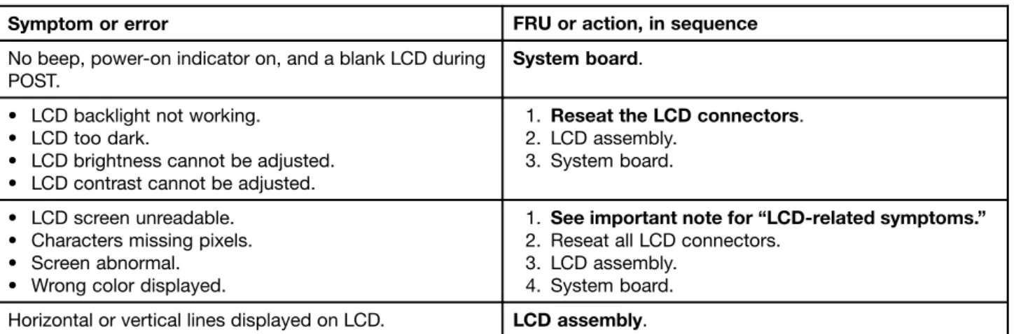
This section contains following information: • “Numeric error codes” on page 45 • “Error messages” on page 46 • “No-beep symptoms” on page 47 • “LCD-related symptoms” on page 47 • “Intermittent problems” on page 48 • “Undetermined problems” on page 48
The symptom-to-FRU index in this section lists symptoms and errors and their possible causes. The most likely cause is listed first, in boldface type.
Note: Do the FRU replacement or other actions in the sequence shown in the column headed “FRU or action, in sequence.” If replacing a FRU does not solve the problem, put the original part back in the computer. Do not replace a nondefective FRU.
This index can also help you determine, during regular servicing, what FRUs are likely to need to be replaced next.
A numeric error is displayed for each error detected in POST or system operation. In the displays,ncan be any number.
If no numeric code is displayed, check the narrative descriptions of symptoms. If the symptom is not described there, go to “Intermittent problems” on page 48.