Embedded System Design Using UML and Platforms
Rong Chen
+, Marco Sgroi
+, Grant Martin
++, Luciano Lavagno
++,
Alberto Sangiovanni- Vincentelli
+, Jan Rabaey
++
University of California, Berkeley ++ Cadence Design Systems {rongchen, sgroi, alberto, jan}@eecs.berkeley.edu; {gmartin, lavagno}@cadence.com
Abstract
Important trends are emerging for the design of embedded systems: a) the use of highly programmable platforms, and b) the use of the Unified Modeling Language (UML) for embedded software development. We believe that the time has come to combine these two concepts into a unified embedded system development methodology. Although each concept is powerful in its own right, their combination magnifies the effective gains in productivity and implementation. This paper defines a UML profile, called UML Platform, and shows how it can be used to represent platforms. As an example, the Intercom platform designed at the Berkeley Wireless Research Center is presented to illustrate the approach.
1 Introduction
Embedded Software (ESW) design is just one, albeit critical, aspect of the more general problem of Embedded System Design (ESD or just ES). ESD is about the implementation of a set of functionalities satisfying a number of constraints ranging from performance to cost, emissions, power consumption and weight. The choice of implementation architecture implies which functionality will be implemented as a hardware component or as software running on a programmable component. In recent years, the functionalities to be implemented in ES have grown in number and complexity so much that the development time is increasingly difficult to predict and to keep in check. The complexity increase coupled with the constantly evolving specifications has forced designers to look at implementations that are intrinsically flexible, i.e., that can be changed rapidly. Since hardware-manufacturing cycles do take time and are expensive, the interest in software-based implementation has risen to previously unseen levels. In software design, little attention has been traditionally paid to hard constraints on reaction speed, memory footprint and power consumption of software. These considerations point to the fact that ESW is really an implementation choice of a functionality that can be indifferently implemented as a hardware component and that we cannot abstract away hard characteristics of software as we have done in the traditional software domain. No wonder then that we are witnessing a crisis in the ES domain for ESW design. This crisis is not likely to be resolved going about business as usual but we need to focus at the root of the problems. Our vision for ESW is to change radically the way in which ESW is developed today by: 1) linking ESW upwards in the abstraction levels to system functionality; 2) linking ESW to the programmable platforms that support it, thus providing the much needed means to verify whether the constraints posed on ES are met. To realize our vision, on one hand we have to develop formal techniques and methods at the abstract level so that verification is started early and with the correct set of tools and methods. On the other hand, we have to think of ESW and hardware architecture in a unified and harmonious way.
UML is the emerging standard meta-notation (a family of related notations) used in the software world to define many aspects of object-oriented software systems [4]. UML is capturing much attention in the ESW community as a possible solution for raising the level of abstraction to a level where productivity can be improved, errors can be easier to identify and correct, better documentation can be provided, and ESW designers can collaborate more effectively. An essential deficiency is that UML standardizes the syntax and semantics of diagrams, but not necessarily the detailed semantics of implementations of the functionality and structure of the diagrams in software. In [2], some requirements are identified that have to be satisfied to make UML a suitable development basis for embedded systems
design, in terms of notation, semantics, refinement steps, and methodologies. The UML Platform profile described in this paper can be considered as a notation to satisfy some of the requirements of [2]. Tools and methodologies based on this notation will be the subject of future work.
Notwithstanding these deficiencies in UML, we believe that its evolution into a usable and well-defined framework for embedded system specification, refinement, analysis and implementation is quite possible. In addition, tool vendors seem quite committed to the necessary UML extensions and changes required to make it a usable meta-notation. For example, the Specification and Description Language (SDL) has been re-defined within a UML 2.0 context so that it can be regarded as a specific "profile" of UML and thus the tools for SDL and UML can continue merging. Moreover, UML has extension facilities (stereotypes, tagged values and constraints) that allow semantically meaningful versions of UML (called UML profiles) to be built for specific application domains. In that sense, UML is not so much a unified language but an infrastructure base for building application-specific languages.
In particular, we believe that the embedded software development process would benefit from a set of modeling tools able to capture the following aspects of the design problem: (1) the QoS requirements of the application, (2) the set of resources, the APIs and QoS of the offered services, and (3) the relationship between different levels of abstraction, especially the mapping and use of resources.
Platform-based design has emerged as one of the key development approaches for complex systems, including embedded systems in the last several years. However, the definition of what was meant by platform had not been crisply given. In [1] and [9] a first attempt at a precise definition of platform-based design was given. An architecture platform is defined as a specific 'family' of micro-architectures, possibly oriented toward a particular class of problems, that can be modified (extended or reduced) by the system developer. A platform instance can be derived from a platform by choosing a set of components from the platform library and setting parameters of re-configurable components. The choice of a platform is driven by cost and time-to-market considerations and is done after exploration of both the application and architecture design spaces. Further, as embedded software developers need a platform abstraction that hides architecture details and defines the services that the platform offers, an API platform is defined in [9] as the Programmer's Model for the abstraction of a multiplicity of computational resources and available peripherals contained within the architectural platform; it is a unique abstract representation of the architecture platform via the software layer. This abstraction usually consists of a software layer that wraps the essential parts of the architecture platform and includes, among others, RTOS and device drivers.
A platform can be described in terms of the type and quality of the services it offers to its users, which can be developers of other services of the same platform, platforms at higher abstraction levels, or applications. In fact, an embedded system application can be considered as a top-level platform, offering services to the controlled environment (e.g. an engine) or the end user (e.g. a person making a cellular phone call). Quality of Service (QoS) parameters, e.g. processing speed and I/O bandwidth, define platform performance and reliability and therefore are the essential distinguishing factors between platforms. The task of the designer is finding the platform that best supports the applications. This requires quantifying the performances of a set of candidate platforms and choos ing the best match between the QoS requirements of the applications and the QoS offered by the platform [3].
When we combine UML, with the platform-based design concept, we see, following the reasoning of [2], that it is necessary to have a way of describing those platforms in UML, i.e., a projection of the platform into the UML notation space. The definition of this projection is the purpose of this paper that articulates a "UML Platform" proposal.
2 Background
2.1 UML
UML is an object-oriented modeling language standardized by the Object Management Group (OMG) mainly for software systems development. It consists of a set of basic building blocks, rules that
dictate the use and composition of these building blocks, and common mechanisms that enhance the quality of the UML models [4].
Its rich notation has made UML a popular modeling language in multiple application domains for system documentation and specification, for capturing user requirements and defining initial software architecture. The use of UML with code generation tools is still quite limited, but is expected to increase as executable dialects are introduced [14][15][16].
To make the system specification phase easier and more flexible, UML provides multiple diagrams to model a system from several perspectives or at multiple level of abstraction. Although different diagrams may have modeling elements in common, their underlying semantics are generally different. Hence, to avoid inconsistencies between models, it is necessary to follow a rigorous design discipline or use tools that enforce consistency.
2.2 Related work
UML already has the capability to model the most relevant real-time systems features, such as performance (using tagged attributes or OCL [10]), resources (using Component or Deployment Diagrams), and time (using classifiers and tagged attributes). However, in absence of a standard and unified modeling approach, the same embedded systems specification may be modeled in several different ways. Therefore, how to use UML for modeling real-time systems has become recently an active area of research and several proposals have been made.
The Real-Time UML profile [3], developed and standardized by OMG, defines a unified framework to express the time, scheduling and performance aspects of a system. It is based on a set of notations that can be used by designers to build models of real-time systems annotated with relevant QoS parameters. Then external tools can perform formal analysis based on these models and provide information on performance and schedulability before the system is built. The profile standardizes an extended UML notation to support the interoperability of modeling and analysis tools but touches little on platform representation.
UML-RT [11] is a profile that extends UML with stereotyped active objects, called capsules, to represent system components. The internal behavior of a capsule is defined using statecharts; its interaction with other capsules takes place by means of protocols that define the sequence of signals exchanged through stereotyped objects called ports. The UML-RT profile defines a model with precise execution semantics; hence it is suitable to capture system behavior and support simulation or synthesis tools (e.g. Rose RT). UML-RT has limited architecture and performance modeling capability and therefore should be considered complementary to the Real-Time UML profile [3].
HASoC [12] is a design methodology based on UML-RT notation. The design flow begins with a description of the system functionality initially given in use case diagrams and then in a UML-RT version properly extended to include annotations with mapping information. The same authors in [5] argue that UML-RT is a too restrictive model because capsules’ behavior is defined by statecharts and propose to associate capsules also with other models of computations such as Synchronous Dataflow, Codesign Finite State Machines etc.
Another approach that combines the informal notation of the UML Diagrams with the formal semantics of SDL is presented in [13]. It consists of a flow from the initial specification phase to the deployment level that specifies the target architecture. The high-level system specification is specified using use case diagrams; the system components and their interactions are described using block diagrams and message sequence charts, respectively. Then the behavior of each module is specified using SDL that provides an executable and simulatable specification.
2.3 Our approach
In this paper, we propose a new UML profile, called UML Platform, to model embedded system platforms. First, we introduce a subset of UML notation (new building blocks using stereotypes and tags) to represent specific platform concepts. Second, we show what are the main levels of abstractions for
platforms and the most common types of relationships between platform components, and how to use appropriate UML diagrams along with aforementioned UML notations to model those platforms and relationships. Third, we explain how to represent platform QoS performance and do constraints budgeting. Finally, we show how to reveal platform services to platform users and developers with the help of the Intercom case study described below.
2.4 Case study: the Intercom
The Intercom [7] is a single -cell wireless network supporting full-duplex voice communication among up to twenty mobile users located in a small geographical area. The network includes a number of units, called remote terminals that operate in one of the following three modes:
♦ idle (the remote is switched on but has not subscribed to the network and cannot participate to a conference with other remotes),
♦ active (the remote has subscribed to the network and is enabled to participate in a conference),
♦ communicating (the remote is participating in a conference).
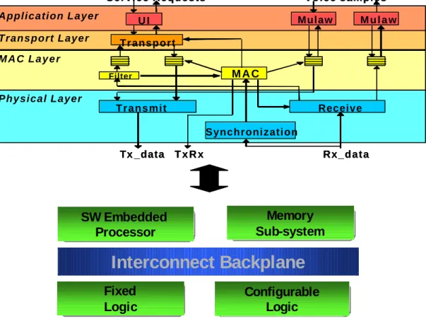
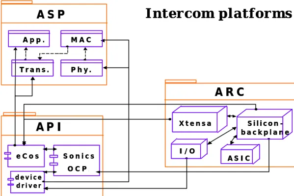
Figure 1. Intercom Protocol Stack and Physical Implementation
Each remote can request one of the following services: subscription to enter active mode, unsubscription to return to idle mode, query of active users, conference with one or multiple remotes, and broadcast communication. The system specification includes also performance requirements on the transmission of voice samples, e.g. latency (below 200 ms), throughput (64 kbps), and requirements on low power consumption. To implement these requirements [7] defines a protocol stack that includes Application, Transport, MAC and Physical layers. Its physical implementation is composed of a reconfigurable embedded processor (Xtensa, running RTOS eCos), a memory subsystem, fixed and configurable logic and a silicon backplane (supporting Sonics OCP) that interconnects these components (Figure 1).
U I M A C T r a n s m i t Synchronization Filter Tx _data R x _ d a t a Mulaw M u l a w Transport Application Layer Transport Layer M A C L a y e r Physical Layer Voice samples T x R x Service Requests Receive
SW Embedded
Processor
SW Embedded
Processor
Sub-system
Memory
Memory
Sub-system
Fixed
Logic
Fixed
Logic
Configurable
Logic
Configurable
Logic
Interconnect Backplane
U I M A C T r a n s m i t Synchronization Filter Tx _data R x _ d a t a Mulaw M u l a w Transport Application Layer Transport Layer M A C L a y e r Physical Layer Voice samples T x R x Service Requests ReceiveSW Embedded
Processor
SW Embedded
Processor
Sub-system
Memory
Memory
Sub-system
Fixed
Logic
Fixed
Logic
Configurable
Logic
Configurable
Logic
3 The UML Platform profile
3.1 New stereotypes and tagged values
In this section, we introduce a set of new stereotypes and tagged values for the UML Platform profile. They are introduced to describe common platform building blocks and their properties, and therefore to properly specialize the general UML notation to the embedded system platform domain. The list of stereotypes and tagged values is derived from the description of several platform examples and, hence, in our opinion it is sufficient to model most embedded platforms.
3.1.1 Stereotyped classifiers
For each of the building blocks that are frequently used in modeling platform components such as processor, device driver, scheduler, table, buffer, memory, cache, etc., a stereotyped classifier is defined. A stereotyped classifier usually includes a set of attributes and methods that are specified only when the block is instantiated at modeling time. For example, the stereotyped class “cache” is associated with attributes such as "valid", "block index", "tag", and "data", methods such as "write through" or "write back", and QoS parameters such as hit time/miss penalty.
3.1.2 Stereotyped relationships
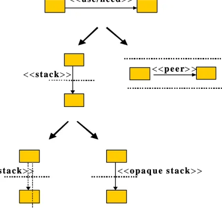
In this subsection, we introduce a set of stereotypes to model the most common relationships between platform components. We organize some of these stereotypes using the hierarchy shown in Figure 2. At the top of the hierarchy, the stereotype <<use>> represents a relations hip in which an entity uses a service provided by a resource, while the stereotype <<need>> indicates when an entity needs a service from another entity, but the service is not currently available, i.e. not implemented. Thus it represents a request for future service enhancements.
Figure 2. Stereotyped Relationship Hierarchy
< <
s t a c k
> >
< <
t r a n s p a r e n t s t a c k
> >
< <
o p a q u e s t a c k
> >
< <
u s e / n e e d
> >
< <
p e e r
> >
< <
s t a c k
> >
< <
t r a n s p a r e n t s t a c k
> >
< <
o p a q u e s t a c k
> >
< <
u s e / n e e d
> >
< <
p e e r
> >
<<stack>> and <<peer>> are refinements of the stereotype <<use>>. <<stack>> is used when the platform component providing the service and the one using it are at different levels of abstraction. We further specialize this stereotyped relationship into <<transparent stack>> and <<opaque stack>>. <<transparent stack>> models the case where the upper level component knows how the service is implemented within the lower level. So, it is possible for the upper entity to bypass the lower one in search of a service that is simpler, but more suited to the requirements. For example, normally a data transfer function interacts with a medium access control (MAC) function to transfer data, but if a faster transferring rate is desired the data transfer function may bypass the MAC function to directly call a device driver to access the network inter-connector. In such case, the data transfer function and the MAC function are related by a transparent stack relationship. <<opaque stack>> describes the case when the upper level component has no knowledge of how the service is implemented by the lower level component. Thus, the upper entity has to always rely on the lower one to provide necessary service. For example, a platform service function written in a high-level language declared as an interrupt service routine always relies on an RTOS to save the microprocessor context, identify the interrupt source, and invoke it whenever the interrupt arrives. Due to the insufficient power of the high-level language, it cannot bypass the RTOS to run on top of a bare microprocessor. In this case, the platform service function and the RTOS form an opaque stack relationship. <<peer>> is used when both the platform component using and the one providing the service are at the same abstraction level. In general, peers can only exist within the same level platform, but stack can exist both within and across one level platform. For example, Application and Transport protocol in Intercom belong to the same platform (ASP platform, see Figure 5), but they are stack-related.
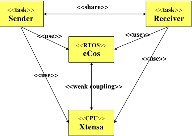
Figure 3. Example of Relationships Outside the hierarchy shown in Figure 2 exist three other relationships that are also very important:
<<communicate>>, <<coupling>>, and <<share>>. <<communicate>> is used to relate two components sharing some information. It can be further specialized by stereotypes representing specific models of
<<
task
>>
Sender
<<
task
>>
Receiver
<<share>>
<<
RTOS
>>
eCos
<<
CPU
>>
Xtensa
<<weak coupling>>
<<use>>
<<use>>
<<use>>
<<use>>
<<
task
>>
Sender
<<
task
>>
Receiver
<<share>>
<<
RTOS
>>
eCos
<<
CPU
>>
Xtensa
<<weak coupling>>
<<use>>
<<use>>
<<use>>
<<use>>
computation, e.g. <<asynchronous>>, <<RPC synchronous>>, <<rendezvous>>, <<Kahn process>>, etc. <<coupling>> reveals the limited freedom in choosing platform components. There are two types of couplings: <<weak coupling>> and <<strong coupling>>. If whenever one entity is chosen, one from a certain group of entities must also be chosen in order to achieve some functionality, then we say a weak coupling exists between this entity and the group; if whenever one entity is chosen, exactly another entity has also to be chosen in order to achieve some functionality, then a strong coupling exists between these two entities. Note that, although the <<coupling>> relationship can be also described in OCL [10], the stereotype form is preferred because it is more visible to users. Figure 3 shows an example of the use of <<weak coupling>> between an RTOS and a CPU. These two entities are coupled because when a CPU is used also an RTOS must be used, and vice versa. This coupling is weak in both directions because there are several types of RTOS that can run on the Xtensa CPU and several CPUs that can support the eCOS RTOS. Finally, we call <<share>> the relationship among multiple entities that use services provided by the same resource (e.g. in Figure 3, tasks sender and receiver share the same CPU). In the presence of <<share>>, it is frequently necessary to deploy an allocation or arbitration scheme, such as a scheduler.
3.1.3 Tagged values
Tagged values (or called tags) are used to extend the properties of a UML building block with additional information. In the UML Platform profile, they are mainly used to specify QoS parameters, application requirements, as well as communication types, usage types, etc. Examples of relevant tags are:
• {throughput}: for communication throughput,
• {delay}: for time delay between request and response,
• {precision}: for calculation precision,
• {power}: for power consumption,
• {size}: for memory size.
3.2 Platforms
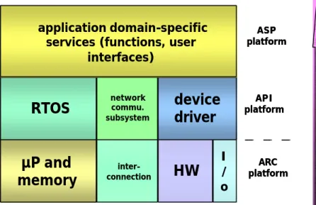
Figure 4. Platforms at Different Levels
We classify embedded system platforms into three abstraction levels: architecture (ARC), application programming interface (API), and application specific programmable (ASP) Platforms (Figure 4). The ARC Layer includes a specific family of micro-architectures (physical hardware), so that the UML deployment diagram is naturally chosen to represent the ARC platform. The API Layer is a software abstraction layer wrapping ARC implementation details. API should be presented by showin g what kinds
ARC platform ASP platform API platform
µP and
memory
connectioninter-I / o
HW
RTOS
networkcommu.subsystem
device
driver
application domain-specific services (functions, user
interfaces) abstraction level low high ARC platform ASP platform API platform
µP and
memory
connectioninter-I / o
HW
RTOS
networkcommu.subsystem
device
driver
application domain-specific services (functions, user
interfaces)
abstraction level
low high
of logical services (represented as interfaces) are provided and how they are grouped together. For example, it is important for users to know that preemption is supported by an RTOS, but not how this service is implemented inside the RTOS because users (either platform users or developers) rarely need to modify the RTOS itself. For such purpose, RTOS, device-driver and network communication subsystem are treated as components, i.e., the physical packaging elements for logical services. In UML, their natural representation is the component diagram.
ASP is a platform, which provides a group of application domain-specific services directly available to users. For example, the function to set up a connection in the Intercom is such a domain-specific service. In addition to calling these existing services, users sometimes also need to modify or combine them, or even develop new services to meet certain requirements. Consequently, unlike API, here it becomes essential to show not only what functionality these services offer, but also how such services are supported by their internal structures, and how they relate to each other. In UML, the class diagram best represents such information.
Figure 5. Intercom Represented by UML Platform Figure 5 shows how Intercom platforms are represented by UML Platform, where:
• ARC, API and ASP platforms are represented by deployment, component and class diagrams respectively;
• <<transparent stack>> relationship exists within the ASP platform (such as the one indicated by dotted line between Transport and MAC); <<opaque stack>> relationship exists between ASP and API (such as the one indicated by solid line between Transport and eCos), and between API and ARC (such as the one between eCos and Xtensa). This implies that Transport may bypass MAC in search of a more suited performance, but it can never bypass eCos;
• <<share>> is used twice: Application and Transport share eCos, while MAC and Physical share device driver.
3.3 QoS parameters
QoS parameters identify key performance properties and therefore allow classifying and comparing different platforms. A set of QoS parameters that completely characterize the needs of any application is
X t e n s a
A R C
I / O A S I CA S P
T r a n s . A p p . e C o sA P I
d e v i c e d r i v e r S o n i c s O C P. M A C S i l i c o n -b a c k p l a n e P h y .I n t e r c o m p l a t f o r m s
X t e n s aA R C
I / O A S I CA S P
T r a n s . A p p . e C o sA P I
d e v i c e d r i v e r S o n i c s O C P. M A C S i l i c o n -b a c k p l a n e P h y .I n t e r c o m p l a t f o r m s
obviously impossible to define. However in our work, as each platform is designed for a particular set of related applications (in contrast to general-purpose computer systems), and each platform is at a particular abstraction level, it becomes possible to decompose QoS properties into just a few orthogonal dimensions (called QoS parameters). For example, for the ARC platform, such dimensions can be power consumption, memory size, processing capability, communication throughput and for the API platform, they can be task-handling number, task-waiting time, etc. As we discuss in Section 3.4, the design constraints can be decomposed along the same dimensions, and this will conceivably enable some form of automatic matching and analysis between QoS properties and design constraints. In [6], the former are called offered QoS (the values are given by the platform providers), the latter required QoS (the constraints on these variables are specified by the platform users), and we adopt such terminologies here.
A platform function can often be implemented through different sets of platform services and, as a result, the values of QoS parameters are also different (for example, the same platform function “transfer data” can be implemented either in software or in hardware, and the resulting transfer delay is different). It is crucial to model such alternatives so that users are able to choose an appropriate implementation that satisfies the desired QoS. In general, we model QoS parameters by annotating classifiers and relationships with tagged values.
3.4 Constraints
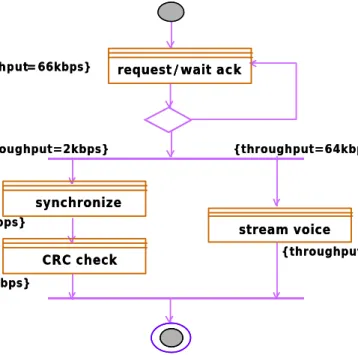
Figure 6. Constraints Budgeting
Embedded system specification requirements usually include not only the functionality that the system has to perform (e.g. user A calls user B) but also a set of constraints on system performance (e.g. the call has to be set up in less than 3 seconds). At any level of abstraction, constraints complement the functional specification with a set of formulae that declare the valid range of variables that are not part of the present specification (e.g. time is not defined in a purely functional specification), but will be introduced later on the way to the final implementation (e.g. after mapping the computation delay of a block is known). When the specification is implemented, one can finally check whether the given constraints on variables like time, area and power are satisfied.
At the beginning of the design process, constraints are defined for the global system performance. As the design moves towards implementation and steps like functional decomposition and refinements are
request/wait ack {throughput=2kbps} {throughput=2kbps} {throughput=2kbps} {throughput=64kbps} {throughput= 66kbps} {throughput=66kbps} synchronize CRC check stream voice {throughput=64kbps} request/wait ack {throughput=2kbps} {throughput=2kbps} {throughput=2kbps} {throughput=64kbps} {throughput= 66kbps} {throughput=66kbps} synchronize CRC check stream voice {throughput=64kbps}
taken, the global constraints must be propagated to the lower levels of abstraction and bound the performances of local components. Constraints defined at a certain specification level are distributed to the components at a lower level by budgeting. The objective of this paper is neither to define a methodology for constraints budgeting and verification nor to propose a new constraint specification formalism in addition to the ones in [8] and [10]. Instead, we provide guidelines on using the UML notation in the budgeting process: we annotate diagrams with tags describing constraints and use the graph structure to show how the lower-level components are connected (either sequentially or concurrently) to drive the budgeting process. An example is shown in Figure 6, where classes are annotated with constraints. Assume we are given a constraint φ on the minimum throughput of a communication node (e.g. an Intercom terminal), and we want to propagate it to lower levels where the node is refined into multiple components. If two components are composed in sequence, φ is simply propagated to both, because throughput is non-additive for series composition. Instead, if two components are composed in parallel, two constraints can be derived, φ1 and φ2, provides their sum does not exceed the original constraint φ.
3.5 Reference applications
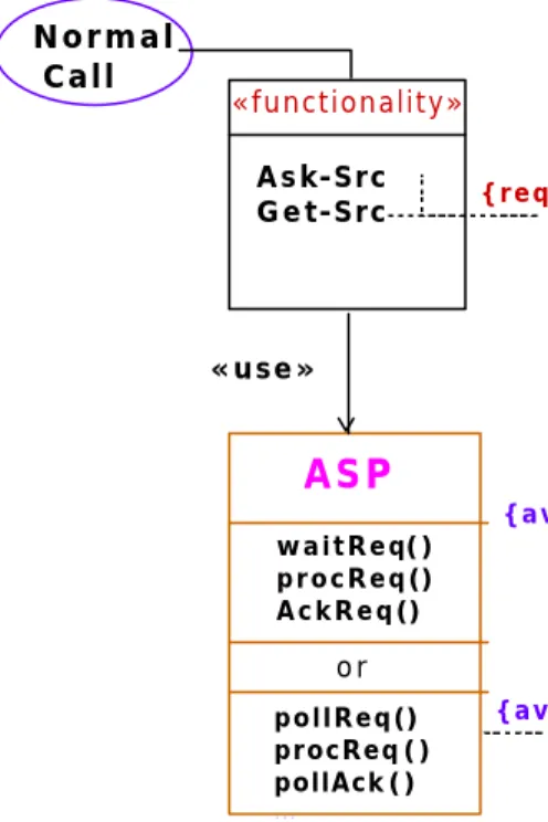
Using reference applications is an easy way to demonstrate how platform services support particular applications. We propose a use case-based approach, which shows the required QoS parameters of reference applications, the corresponding offered QoS parameters of platform services, and indicates stereotyped relationships between applications and platform services.
Figure 7 shows an Intercom example of a reference application and the available services it may use. The requirement for setting up a normal call is that delay is less than 3 s. This can be met by two groups of the ASP platform services whose QoS delay parameters are less than 2.5 s and 2 s respectively.
Figure 7. Reference Applications and Extension Points
3.6 Platform extension points
One basic idea of platform-based design is that a platform should be able to support a set of similar or related applications, and some of them may emerge even after the platform has been developed. For a platform to support those unforeseen applications, its service must be extensible. The places within a
«functionality» ASP waitReq() procReq() A c k R e q () pollReq() procReq () pollAck () ... Normal Call A s k-Src G e t-Src {required|delay<3s} o r «use» {available|delay<2s} {available|delay<2.5s} «functionality» API priorityTask () preemptTask() E m e r . Call Tear-Src Get- Src {required|preemption} « n e e d » {potential|preemption feature available}
platform where new services can be added to accommodate new applications are called extension points. And, these extension points must be clearly marked to facilitate future platform development.
Platform extension points can be represented in two ways. One is to use the <<need>> relationship. For example, Figure 7 shows that an emergency call requires the capability of preempting other normal calls in case all calling time slots are busy, but no service of the current ASP platform provides such preemption feature. However, by using functions provided by the lower API platform (e.g. priorityTask(), preemptTask()), preemption is potentially available as an ASP service: we refer to this as an extension point of the platform, and we express it using the <<need>> relationship. The other way to present extension points is to unveil potential alternatives by <<transparent stack>> relationship. For example, Figure 5 shows a <<transparent stack>> relationship between Transport and MAC: in this case Transport can bypass MAC in search of services with more suited QoS parameters.
Extension points can also be distinguished into: public, if they are done by platform providers, and
proprietary, if they are done by platform users.
4 Conclusions
In this paper we discuss why a new UML profile is necessary for modeling embedded system platforms, and then demonstrate how such a profile, called UML Platform, can be constructed by (1) introducing new building blocks to represent specific platform concepts, (2) choosing proper UML diagrams and notations to model platforms at different abstraction levels and their relationships, (3) quantifying QoS performance and budgeting constraints, (4) revealing platform services and extension points. Developing a full-fledged embedded system design methodology and tool set based on UML Platform, i.e., how to exactly take full advantages of these platform descriptor notations to ease the design process, is our on-going research work.
5 References
[1] A. Sangiovanni-Vincentelli and A. Ferrari, System Design – Traditional Concepts and New Paradigms, Proceedings of ICCD 99, Austin, October, 1999, pp.2-12.
[2] G. Martin, L. Lavagno, J. Louis -Guerin, Embedded UML: a merger of real-time UML and co-design, Proceedings of CODES 2001, Copenhagen, April 2001, pp.23-28.
[3] B. Selic, A Generic Framework for Modeling Resources with UML, IEEE Compu. Soc, June 2000, pp.64-9 [4] J. Rumbaugh, I. Jacobson, and G. Booch, The Unified Modeling Language User Guide, Addison-Wesley, 1998 [5] P.Green, M. Edwards, S. Essa, UML for System-Level Design, Forum on Design Languages, Proceedings of FDL 2001, Lyon, France, Sept. 3-7, 2001
[6] ARTiSAN Software Tools, Inc. et al., Response to the OMG RFP for Schedulability, Performance, and Time, OMG document number: ad/2001-06-14, June, 2001
[7] J. da Silva Jr., M. Sgroi, F. De Bernardinis, S.F Li, A. Sangiovanni-Vincentelli and J. Rabaey, Wireless Protocols Design: Challenges and Opportunities. Proceedings of the 8th IEEE International Workshop on Hardware/Software Codesign, CODES '00, S.Diego, CA, USA, May 2000.
[8] Rosetta, www.sldl.org
[9] A. Sangiovanni-Vincentelli, Defining Platform-based Design, EEDesign, February 2002.
[10] J. Warmer, A. Kleppe, The Object Constraint Language: Precise Modeling with UML, Object Technology Series, Addison-Wesley, 1999.
[11] B. Selic, J. Rumbaugh, Using UML for Modeling Complex Real-Time Systems, White paper, Rational (Object Time), March 1998.
[12] P. N. Green, M. D. Edwards, The modeling of Embedded Systems Using HASoC, Proceedings of DATE 02. [13] G. de Jong, A UML-Based Design Methodology for Real-Time and Embedded Systems, Proceedings of DATE 02.
[14] UML RFP, http://www.omg.org/techprocess/meetings/schedule/Action_Semantics_for_UML_RFP.html [15] B. Selic, Complete High-Performance Code Generation from UML Models, Proceedings of Embedded System Conference, San Francisco, CA, USA, March 2002.
[16] C. Raistrick, Executable UML for Embedded System Development, Proceedings of Embedded System Conference, San Francisco, CA, USA, March 2002.