Corporate Headquarters Cisco Systems, Inc.
170 West Tasman Drive San Jose, CA 95134-1706 USA http://www.cisco.com Tel: 408 526-4000 800 553-NETS (6387) Fax: 408 526-4100
Cisco IP Videoconferencing Solution
Reference Network Design Guide
THE SPECIFICATIONS AND INFORMATION REGARDING THE PRODUCTS IN THIS MANUAL ARE SUBJECT TO CHANGE WITHOUT NOTICE. ALL STATEMENTS, INFORMATION, AND RECOMMENDATIONS IN THIS MANUAL ARE BELIEVED TO BE ACCURATE BUT ARE PRESENTED WITHOUT WARRANTY OF ANY KIND, EXPRESS OR IMPLIED. USERS MUST TAKE FULL RESPONSIBILITY FOR THEIR APPLICATION OF ANY PRODUCTS. THE SOFTWARE LICENSE AND LIMITED WARRANTY FOR THE ACCOMPANYING PRODUCT ARE SET FORTH IN THE INFORMATION PACKET THAT SHIPPED WITH THE PRODUCT AND ARE INCORPORATED HEREIN BY THIS REFERENCE. IF YOU ARE UNABLE TO LOCATE THE SOFTWARE LICENSE OR LIMITED WARRANTY, CONTACT YOUR CISCO REPRESENTATIVE FOR A COPY.
The Cisco implementation of TCP header compression is an adaptation of a program developed by the University of California, Berkeley (UCB) as part of UCB’s public domain version of the UNIX operating system. All rights reserved. Copyright © 1981, Regents of the University of California.
NOTWITHSTANDING ANY OTHER WARRANTY HEREIN, ALL DOCUMENT FILES AND SOFTWARE OF THESE SUPPLIERS ARE PROVIDED “AS IS” WITH ALL FAULTS. CISCO AND THE ABOVE-NAMED SUPPLIERS DISCLAIM ALL WARRANTIES, EXPRESSED OR IMPLIED, INCLUDING, WITHOUT
LIMITATION, THOSE OF MERCHANTABILITY, FITNESS FOR A PARTICULAR PURPOSE AND NONINFRINGEMENT OR ARISING FROM A COURSE OF DEALING, USAGE, OR TRADE PRACTICE.
IN NO EVENT SHALL CISCO OR ITS SUPPLIERS BE LIABLE FOR ANY INDIRECT, SPECIAL, CONSEQUENTIAL, OR INCIDENTAL DAMAGES, INCLUDING, WITHOUT LIMITATION, LOST PROFITS OR LOSS OR DAMAGE TO DATA ARISING OUT OF THE USE OR INABILITY TO USE THIS MANUAL, EVEN IF CISCO OR ITS SUPPLIERS HAVE BEEN ADVISED OF THE POSSIBILITY OF SUCH DAMAGES.
Cisco IP Videoconferencing Solution Reference Network Design Guide
Copyright © 2002, Cisco Systems, Inc. All rights reserved.
CCIP, the Cisco Arrow logo, the Cisco Powered Network mark, the Cisco Systems Verified logo, Cisco Unity, Follow Me Browsing, FormShare, Internet Quotient, iQ Breakthrough, iQ Expertise, iQ FastTrack, the iQ Logo, iQ Net Readiness Scorecard, Networking Academy, ScriptShare, SMARTnet, TransPath, and Voice LAN are trademarks of Cisco Systems, Inc.; Changing the Way We Work, Live, Play, and Learn, Discover All That’s Possible, The Fastest Way to Increase Your Internet Quotient, and iQuick Study are service marks of Cisco Systems, Inc.; and Aironet, ASIST, BPX, Catalyst, CCDA, CCDP, CCIE, CCNA, CCNP, Cisco, the Cisco Certified Internetwork Expert logo, Cisco IOS, the Cisco IOS logo, Cisco Press, Cisco Systems, Cisco Systems Capital, the Cisco Systems logo, Empowering the Internet Generation, Enterprise/Solver, EtherChannel, EtherSwitch, Fast Step, GigaStack, IOS, IP/TV, LightStream, MGX, MICA, the Networkers logo, Network Registrar, Packet, PIX, Post-Routing, Pre-Routing, RateMUX, Registrar, SlideCast, StrataView Plus, Stratm, SwitchProbe, TeleRouter, and VCO are registered trademarks of Cisco Systems, Inc. and/or its affiliates in the U.S. and certain other countries.
All other trademarks mentioned in this document or Web site are the property of their respective owners. The use of the word partner does not imply a partnership relationship between Cisco and any other company. (0206R)
C O N T E N T S
Preface
viiPurpose
viiScope
viiAudience
viiiOrganization
viiiObtaining Documentation
ixWorld Wide Web
ixDocumentation CD-ROM
ixOrdering Documentation
ixDocumentation Feedback
ixObtaining Technical Assistance
xCisco.com
xTechnical Assistance Center
xCisco TAC Web Site
xiCisco TAC Escalation Center
xiC H A P T E R 1
Introduction
1-1H.323 Basics
1-1Videoconferencing with H.323
1-2H.323 Videoconferencing Components
1-3Video Terminal
1-4Gatekeeper
1-5Gateway
1-6Multipoint Conference Unit (MCU)
1-7Proxy
1-8C H A P T E R 2
Deployment Models
2-1Composite Deployment Model
2-1Campus Single Zone
2-3Campus Multi Zone
2-4WAN Single Zone
2-5WAN Multi Zone
2-7Contents C H A P T E R 3
Campus Infrastructure
3-1Network Infrastructure
3-1Single-Zone Campus
3-2Multi-Zone Campus
3-3Quality of Service
3-4Traffic Classification Types
3-4Trust Boundaries
3-5QoS Features Summary
3-6C H A P T E R 4
WAN Infrastructure
4-1Single-Zone WAN
4-2Traffic Classification
4-3Call Admission Control (CAC)
4-4Provisioning
4-4Priority Queuing on the WAN
4-4Entrance Criteria
4-4Multi-Zone WAN
4-5Traffic Classification
4-7Bandwidth Control and Call Admission Control (CAC)
4-7Provisioning
4-7Priority Queuing on the WAN
4-8Entrance Criteria
4-8C H A P T E R 5
WAN QoS
5-1WAN QoS Model
5-1Capacity Planning
5-2QoS Tools
5-2Traffic Classification
5-3Proxy Usage
5-3Traffic Prioritization
5-3Best Practices
5-5Contents
C H A P T E R 6
Dial Plan Architecture
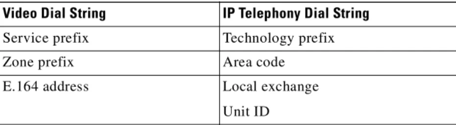
6-1Dial Plan Components
6-1Service Prefix Design
6-2MCU Service Prefixes
6-3Gateway Service Prefixes
6-3Single-Zone Dial Plan
6-4Zone Prefix Design
6-6Multi-Zone Dial Plan
6-8C H A P T E R 7
Call Routing
7-1Call Routing Scenarios
7-1Routing PSTN Calls to H.323
7-4Routing Inbound PSTN Calls in a Single-Zone Network
7-5Routing Inbound PSTN Calls in a Multi-Zone Network
7-8Routing Inter-Zone Calls Using Hopoff Statements
7-8Routing Inter-Zone Calls Using a Directory Gatekeeper
7-10C H A P T E R 8
Cisco Video Infrastructure Components
8-1Cisco IP/VC 3540 MCU and Gateway
8-1Cisco IP/VC 3510 MCU
8-3Initiating a Call
8-3Cascading MCUs
8-4Distributed MCUs
8-5Video Gateways
8-6Service Prefixes
8-7Line Hunting
8-8Cisco IP/VC 3530 VTA
8-10Cisco Multimedia Conference Manager (MCM)
8-12Gatekeeper
8-13HSRP
8-15Proxy
8-16Contents
C H A P T E R 9
Multi-Zone WAN Case Study
9-1Network Topology
9-1Network Design
9-3Quality of Service (QoS)
9-3Call Admission Control
9-3Dial Plan
9-5Zone Prefixes
9-5Service Prefixes
9-5E.164 Addresses and H.323-IDs
9-6Video Infrastructure
9-7A P P E N D I X A
Resource Reservation Protocol (RSVP)
A-1GL O S S A R Y
Preface
This preface describes the purpose, scope, intended audience, and general organization of this Cisco IP
Videoconferencing Solution Reference Network Design Guide. It also provides information on how to
order documentation from Cisco Systems.
Purpose
This document provides guidelines, recommendations, and best practices to help you design an IP videoconferencing solution for your enterprise using the Cisco Architecture for Voice, Video, and Integrated Data (AVVID).
Scope
This document describes the products and features used to build a Cisco IP Videoconferencing (IP/VC) system, and it gives recommendations on how to combine those elements into an effective solution for your enterprise. However, this document does not contain specific implementation or configuration details for the products and features. For details about a particular product or feature, refer to the technical documentation available online at Cisco.com. (See Obtaining Documentation, page ix.)
Note Unless stated otherwise, the solution designs presented in this document require the minimum software releases listed in Table 1, and the information presented here applies only to those releases.
Table 1 Cisco IP/VC Hardware Platforms and Minimum Software Releases
Platform Minimum Required Software Release
IPVC 3510 Multipoint Conference Unit (MCU) 2.2.1
IPVC 3520 Gateway 2.2.3
IPVC 3525 Gateway 2.2.3
IPVC 3530 Video Terminal Adapter (VTA) 1.0 IPVC 3540 Gateway Module 1.0.9.1 IPVC 3540 Multipoint Conference Unit (MCU) 2.155
Preface Audience
Audience
This document is intended for Cisco customers, partners, and systems engineers who will be designing and implementing an IP videoconferencing solution in the enterprise environment.
Organization
This guide contains the chapters and information listed in the following table.
Note Cisco strongly recommends that you carefully read chapters 1 and 2 before attempting to design an IP videoconferencing solution and before reading any other sections of this guide.
Chapter Title Description
1 Introduction Presents basic concepts related to IP videoconferencing and the H.323 standard.
2 Deployment Models Describes the primary models used to deploy an IP videoconferencing solution and explains when to use each model.
Note This guide makes frequent references to these deployment models. Cisco recommends that you read this chapter carefully and understand the main characteristics of each model.
3 Campus Infrastructure Lists considerations and guidelines for deploying IP videoconferencing with Quality of Service (QoS) in a campus environment (or LAN).
4 WAN Infrastructure Presents considerations and guidelines for deploying videoconferencing across an IP WAN.
5 WAN QoS Describes key Quality of Service (QoS) features of the Cisco AVVID network infrastructure and how they apply to IP videoconferencing over a WAN.
6 Dial Plan Architecture Lists important considerations for designing an effective
videoconferencing dial plan, and explains some of the implementation mechanisms available.
7 Call Routing Describes the main call routing methods used with Cisco gatekeeper and Cisco IP/VC equipment in an H.323 video network, and lists guidelines for using each method.
8 Cisco Video Infrastructure Components
Describes the various components of the video network infrastructure, such as the Cisco Multimedia Conference Manager and the Multipoint Conference Units, and presents guidelines for their use in the enterprise environment.
9 Multi-Zone WAN Case Study Presents an extended example of a multi-zone WAN implementation that employs many of the concepts and techniques discussed in this guide.
A Resource Reservation Protocol (RSVP) Gives a few brief recommendations about using RSVP for call admission control.
Preface
Obtaining Documentation
Obtaining Documentation
The following sections explain how to obtain documentation from Cisco Systems.
World Wide Web
You can access the most current Cisco documentation on the World Wide Web at the following URL:
http://www.cisco.com
Translated documentation is available at the following URL:
http://www.cisco.com/public/countries_languages.shtml
Documentation CD-ROM
Cisco documentation and additional literature are available in a Cisco Documentation CD-ROM package, which is shipped with your product. The Documentation CD-ROM is updated monthly and may be more current than printed documentation. The CD-ROM package is available as a single unitor through an annual subscription.
Ordering Documentation
Cisco documentation is available in the following ways:
• Registered Cisco Direct Customers can order Cisco product documentation from the Networking Products MarketPlace:
http://www.cisco.com/cgi-bin/order/order_root.pl
• Registered Cisco.com users can order the Documentation CD-ROM through the online Subscription Store:
http://www.cisco.com/go/subscription
• Nonregistered Cisco.com users can order documentation through a local account representative by calling Cisco corporate headquarters (California, USA) at 408 526-7208 or, elsewhere in North America, by calling 800 553-NETS (6387).
Documentation Feedback
If you are reading Cisco product documentation on Cisco.com, you can submit technical comments electronically. Click Leave Feedback at the bottom of the Cisco Documentation home page. After you complete the form, print it out and fax it to Cisco at 408 527-0730.
You can e-mail your comments to [email protected].
To submit your comments by mail, use the response card behind the front cover of your document, or write to the following address:
Cisco Systems
Attn: Document Resource Connection 170 West Tasman Drive
Preface Obtaining Technical Assistance
We appreciate your comments.
Obtaining Technical Assistance
Cisco provides Cisco.com as a starting point for all technical assistance. Customers and partners can obtain documentation, troubleshooting tips, and sample configurations from online tools by usingthe Cisco Technical Assistance Center (TAC) Web Site. Cisco.com registered users have complete access to the technical support resources on the Cisco TAC Web Site.
Cisco.com
Cisco.com is the foundation of a suite of interactive, networked services that provides immediate, open access to Cisco information,networking solutions, services, programs, and resources at any time, from anywhere in the world.
Cisco.com is a highly integrated Internet application and a powerful, easy-to-use tool that provides a broad range of features and services to help you to
• Streamline business processes and improve productivity • Resolve technical issues with online support
• Download and test software packages
• Order Cisco learning materials and merchandise
• Register for online skill assessment, training, and certification programs
You can self-register on Cisco.com to obtain customized information and service. To access Cisco.com, go to the following URL:
http://www.cisco.com
Technical Assistance Center
The Cisco TAC is available to all customers who need technical assistance with a Cisco product, technology, or solution. Two types of support are available through the Cisco TAC: the Cisco TAC Web Site and the Cisco TAC Escalation Center.
Inquiries to Cisco TAC are categorized according to the urgency of the issue:
• Priority level 4 (P4)—You need information or assistance concerning Cisco product capabilities, product installation, or basic product configuration.
• Priority level 3 (P3)—Your network performance is degraded. Network functionality is noticeably impaired, but most business operations continue.
• Priority level 2 (P2)—Your production network is severely degraded, affecting significant aspects of business operations. No workaround is available.
• Priority level 1 (P1)—Your production network is down, and a critical impact to business operations will occur if service is not restored quickly. No workaround is available.
Which Cisco TAC resource you choose is based on the priority of the problem and the conditions of service contracts, when applicable.
Preface
Obtaining Technical Assistance
Cisco TAC Web Site
The Cisco TAC Web Site allows you to resolve P3 and P4 issues yourself, saving both cost and time. The site provides around-the-clock access to online tools, knowledge bases, and software. To access the Cisco TAC Web Site, go to the following URL:
http://www.cisco.com/tac
All customers, partners, and resellers who have a valid Cisco services contract have complete access to the technical support resources on the Cisco TAC Web Site. The Cisco TAC Web Siterequires a Cisco.com login ID and password. If you have a valid service contract but do not have a login ID or password, go to the following URL to register:
http://www.cisco.com/register/
If you cannot resolve your technical issues by using the Cisco TAC Web Site, and you are a Cisco.com registered user, you can open a case online by using the TAC Case Open tool at the following URL:
http://www.cisco.com/tac/caseopen
If you have Internet access, it is recommended that you open P3 and P4 cases through the Cisco TAC Web Site.
Cisco TAC Escalation Center
The Cisco TAC Escalation Center addresses issues that are classified as priority level 1 or priority level 2; these classifications are assigned when severe network degradation significantly impacts business operations. When you contact the TAC Escalation Center with a P1 or P2 problem, a Cisco TAC engineer will automatically open a case.
To obtain a directory of toll-free Cisco TAC telephone numbers for your country, go to the following URL:
http://www.cisco.com/warp/public/687/Directory/DirTAC.shtml
Before calling, please check with your network operationscenter to determine the level of Cisco support services to which your company is entitled; for example, SMARTnet, SMARTnet Onsite, or Network Supported Accounts (NSA). In addition, please have available your service agreement number and your product serial number.
Preface Obtaining Technical Assistance
C H A P T E R
1
Introduction
This chapter provides an overview of the H.323 standard and the video infrastructure components used to build an H.323 videoconferencing network. It describes the basics of the H.323 video standard and infrastructure components used throughout this guide.
H.323 Basics
The H.323 standard provides a foundation for audio, video, and data communications across Internet Protocol (IP) networks. H.323 is an umbrella recommendation from the International
Telecommunications Union (ITU) that sets standards for multimedia communications over local area networks (LANs). The H.323 standard is part of a larger range of videoconferencing standards (H.32x) for videoconferencing over various network media. For example, H.320 supports videoconferencing over Integrated Services Digital Network (ISDN), H.321 supports videoconferencing over
Asynchronous Transfer Mode (ATM), H.324 supports videoconferencing over standard Plain Old Telephone Service (POTS) lines, and H.323 supports videoconferencing over IP LANs.
The H.323 specification consists of multiple protocols, including:
• H.245 — Provides control signaling used to exchange end-to-end control messages. These control messages carry information relating to:
– Capabilities exchange
– Opening and closing of logical channels used to carry media streams
– Flow control messages
– General commands and indications
• H.225 — Provides registration, admission, and status (RAS), which is the protocol used between H.323 devices and the gatekeeper for device registration. The RAS protocol is used to perform registration, admission control, bandwidth utilization updates, status, and disengagement
procedures between H.323 devices and the gatekeeper. H.225 is also used during call setup to open a call signaling channel using standard Q.931 messaging protocol.
Chapter 1 Introduction Videoconferencing with H.323
Videoconferencing with H.323
Historically, videoconferencing was done primarily over ISDN and time division multiplexed (TDM) networks using standard H.320. Running interactive video over data networks was not an option due to video’s shared media characteristics, connection-less nature, and lack of guaranteed data flows. With the introduction of switched 10/100 Mbps networks, high-end routers, and Layer 2 and Layer 3 quality of service (QoS), delivering interactive video over IP is now a reality. Today there is a large installed base of H.320 networks that incur large monthly access and switched usage charges.
With the current advances to the IP networks, it is now possible to run interactive video over an IP network, thus saving customers thousands of dollars a month by converging voice, video, and data traffic over a common path. Costs drop even further as videoconferencing terminals no longer need to support complex network aggregation devices such as Inverse Multiplexers (IMUXs) and can instead rely on simple Ethernet network interface cards (NICs) for network connectivity.
H.323 builds on top of existing IP data networks, ultimately saving money and scaling to larger deployments. The resulting drop in cost per seat is expected to cause an exponential increase in the number of H.323 terminals deployed as users move videoconferencing assets from shared areas, such as conference rooms, to the user desktop. For example, distance learning and business meetings are two common applications that can be deployed effectively with H.323 over IP networks.
Table 1-1 Protocols Supported by the H.323 Standard
Standard Supported Functions
H.225 RAS, Call Setup and Tear Down (Q.931 call establishment) H.245 Call Control Messaging
H.261 H.263 Video Formats G.711 G.722 G.723 G.728 Audio Formats
Chapter 1 Introduction
H.323 Videoconferencing Components
H.323 Videoconferencing Components
Five components make up an H.323 videoconferencing network: • Video Terminal, page 1-4
• Gatekeeper, page 1-5
• Gateway, page 1-6
• Multipoint Conference Unit (MCU), page 1-7
• Proxy, page 1-8
Cisco offers product solutions for all the above components except video terminals, which are covered in detail in Chapter 8, Video Infrastructure. Figure 1-1 illustrates a typical H.323 videoconferencing network.
Figure 1-1 H.323 Videoconferencing Infrastructure Components
MCUs Cisco IOS based
gatekeeper/proxy H.323 Video terminal Video terminal adapter H.320 Video terminal Video gateway BRI, PRI, or v.35 PSTN ISDN H.323 Video terminal 74651
Chapter 1 Introduction H.323 Videoconferencing Components
Video Terminal
Video terminals come in many forms, including video systems installed on PCs as standalone desktop terminals and group-focused shared conference room devices. Figure 1-2 illustrates the functional components in an H.323 video terminal.
Figure 1-2 Functional Components of a Video Terminal
Video conferencing user interface System control H.245 Control Q.931 Call setup H.225 RAS gatekeeper interface 74652 Data interface T.120 Camera display Video codec H.261 H.263 Microphone speakers Audio codec G.711 G.723 G.729 RTP LAN interface
Chapter 1 Introduction
H.323 Videoconferencing Components
Gatekeeper
The gatekeeper is one of the most important components of an H.323 videoconferencing network. Although the H.323 standard lists the gatekeeper as an optional device, you cannot build a scalable video network without the application controls the gatekeeper provides. Each video infrastructure component registers with the gatekeeper. The gatekeeper performs all address resolution, bandwidth management, admission control, zone management, and intra-zone and inter-zone call routing.
A zone is a logical grouping of H.323 infrastructure components registered to, and managed by, a single gatekeeper. Zones are not dependent on physical network topology or IP subnets. Zones, which may span one or more network segments or IP subnets, are simply a logical grouping of devices. As such, zones can be defined based on geographical proximity, bandwidth availability, or other criteria.
The most fundamental function of a gatekeeper is to provide address resolution, thus allowing terminals, gateways, and MCUs to be addressed using the international E.164 address standard and/or an H.323 alias. Each endpoint that is registered to a gatekeeper must be assigned a unique E.164 address (numeric identifier). As a result, zone prefixes are used in the H.323 video network to identify zones, similar to the use of area codes in telephony systems.
Throughout this document are example topologies that are based on single-zone and multi-zone configurations. For example, Figure 1-3 illustrates a single zone.
Figure 1-3 Single H.323 Zone
MCU Gatekeeper H.323 Zone H.323 Endpoint Video gateway PSTN ISDN 74653
Chapter 1 Introduction H.323 Videoconferencing Components
Gateway
Gateways provide interoperability between H.323 elements and an installed base of H.320 units. The H.323 gateway allows H.323 video terminals to communicate with other H.32x video terminals, such as H.320 and H.321 video terminals. Video gateways perform translation between different protocols, audio encoding formats, and video encoding formats that may be used by the various H.32x standards. For example, the ISDN H.320 standard uses the H.221 protocol for signaling, while the H.323 standard uses H.225. The gateway must translate between these two protocols to allow devices of different network media and protocols to communicate with each other. Figure 1-4 illustrates the role of a gateway in an H.323 video network.
Figure 1-4 Functional Components of an H.323 Video Gateway
74654
IP Terminal processing
ISDN/PSTN Processing Transmission and communication
format translation H.245/H.242 H.225/H.221 Audio transcoding G.711/G.722 G.711/G.723 G.711/G.728 PSTN ISDN H.320 Video terminal H.323 Video terminal
Chapter 1 Introduction
H.323 Videoconferencing Components
Multipoint Conference Unit (MCU)
Video terminals are generally point-to-point devices, allowing only two participants per conversation. A multipoint conference unit (MCU) allows video conferences to be extended to three or more participants. An MCU consists of a multipoint controller (MC) and a multipoint processor (MP). The MC manages all call setup control functions and conference resources as well as the opening and closing of media streams. The MP processes audio and video media streams only. Cisco MCUs can be stacked to create more conferences or cascaded to create larger conferences. Stacking and cascading are covered in detail
in Chapter 8, Video Infrastructure. Figure 1-5 illustrates the function of an MCU.
Figure 1-5 Functional Components of an MCU
74655
Multipoint controller call setup resource management redirection
Conference control MCU
LAN Interface
Multipoint processor audio and video mixing
H.323 Video terminal H.323 Video terminal H.323 Video terminal
Chapter 1 Introduction H.323 Videoconferencing Components
Proxy
A proxy is a call processing agent that terminates H.323 calls from a local LAN or zone and establishes sessions with H.323 endpoints located in other LANs or zones. In so doing, the proxy provides network administrators with the ability to set and enforce quality of service (QoS) on inter-zone segments. The proxy also provides a method of identifying H.323 videoconferencing connections for tunneling through firewalls and Network Address Translation (NAT) environments. Figure 1-6 illustrates a proxy call over a WAN link.
Figure 1-6 Proxy Call Over a WAN Link
H.323 Video terminal 1 H.323 Video terminal 2 Gatekeeper proxy Qos-Enabled IP WAN Leg 1
-Terminated call from video terminal 1 to proxy
Leg 2
-QoS-Enabled call from proxy to proxy with IP precedence 4 or RSVP
Leg 3
-Terminated from proxy to video terminal 2 Gatekeeper
proxy
C H A P T E R
2
Deployment Models
This chapter introduces four basic design models used to deploy IP videoconferencing solutions: • Campus Single Zone, page 2-3
• Campus Multi Zone, page 2-4
• WAN Single Zone, page 2-5
• WAN Multi Zone, page 2-7
This chapter provides basic design criteria and guidelines for selecting the correct deployment model. Subsequent chapters of this design guide describe in more detail each of the basic models introduced here.
Composite Deployment Model
Figure 2-1 illustrates a composite topology that encompasses all of the deployment models discussed in this guide. All designs discussed in this chapter are supported with currently shipping products. The overall goals of a Cisco-based H.323 videoconferencing solution are as follows:
• Provide end-to-end IP video connectivity across the corporate infrastructure, with business quality
transmission. Business quality video is defined as 30 frames per second operation with a minimum of Common Intermediate Format (CIF) resolution. Typically, this level of quality requires 384 kbps of application bandwidth for most video terminals.
• Provide quality of service (QoS) — high availability with low latency and jitter (delay variability). • Reduce Integrated Services Digital Network (ISDN) costs by eliminating the need for ISDN
attachments directly to video terminals.
• Allow Public Switched Telephone Network (PSTN) access to legacy H.320 systems through shared gateway resources.
• Support multipoint calling through Multipoint Conference Units (MCUs).
• Conserve WAN bandwidth by distributing MCU and gateway resources across the IP infrastructure. • Lower total cost of ownership for the video network by utilizing the existing IP infrastructure. • Support manageability of multiple H.323 elements in a distributed network topology.
Chapter 2 Deployment Models Composite Deployment Model
Figure 2-1 Composite Deployment Model
74657 Si Si Si H.323 Terminals H.323 Terminals MCU MCU Gatekeeper proxy Gatekeeper proxy H.323 to H.320 Gateway H.323 to H.320 Gateway H.320 MCU H.320 Endpoints PSTN ISDN QoS Enabled IP WAN Large branch with one or more zones, local PSTN, and MCU access
Headquarters with one or more zones, and local PSTN and MCU access
Small branch with no local gatekeeper, PSTN or MCU services. All services will be handled at headquarters site
Chapter 2 Deployment Models
Campus Single Zone
Campus Single Zone
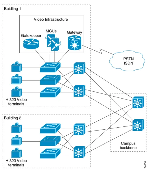
Figure 2-2 illustrates an H.323 network in a campus environment configured with a single zone. This is the most basic design model to implement and is used in pilot installs and smaller video environments.
Figure 2-2 Campus Single Zone
The campus single-zone deployment model has the following design characteristics: • A single gatekeeper supporting a single zone for H.323 video.
• All H.323 video users registered with the single gatekeeper. (See Chapter 8 for gatekeeper registration limits.)
• Optional PSTN access available through the Cisco IP/VC 352X gateway.
• Optional multipoint conferencing available through the Cisco IP/VC 3510 MCU. • Zone bandwidth managed by the configured gatekeeper.
• All gateway and MCU services registered and managed by a single gatekeeper. • Call routing between endpoints using fully qualified E.164 addresses or H.323-ID.
Si Si Campus backbone 74658 Si Si MCUs Gateway Gatekeeper Video Infrastructure PSTN ISDN Buidling 1 H.323 Video terminals Si Si Building 2 H.323 Video terminals
Chapter 2 Deployment Models Campus Multi Zone
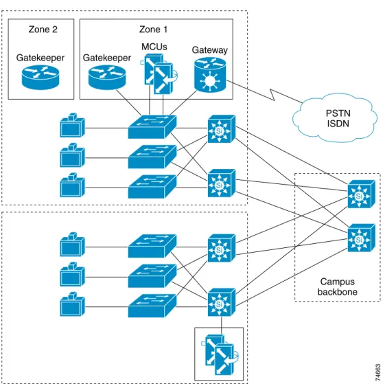
Campus Multi Zone
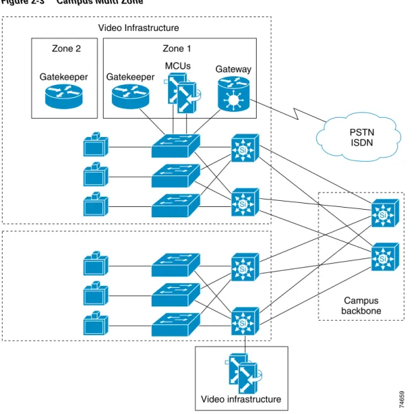
Figure 2-3 illustrates a multi-zone H.323 video network in a campus environment. This model is most often implemented in an enterprise campus network. Depending on business function, administrators may choose to create different zones for security reasons. For example, company executives may be registered in a single zone that is separate from other users to allow administrators to limit access to those video terminals. In addition, as a video network grows, a single zone may not be manageable because of the number of users or the ability to manage network resources.
Note Multiple zones can be configured on a single router. If you configure multiple local zones on a single router, and MCUs and/or gateways are registered with the zones, you must add hopoff statements for each service prefix. If hopoffs are not added for each service prefix, the video terminal will not be able to access MCUs or gateways outside its local zone. See Routing Inter-Zone Calls Using Hopoff Statements, page 7-8, for more information.
Figure 2-3 Campus Multi Zone
Video infrastructure Si Si Campus backbone 74659 Si Si MCUs Gateway Gatekeeper Gatekeeper Zone 1 Zone 2 Video Infrastructure PSTN ISDN Si Si
Chapter 2 Deployment Models
WAN Single Zone
The campus multi-zone deployment model has the following design characteristics: • Multiple gatekeepers supporting multiple zones for H.323 video.
• H.323 endpoints register with one of the multiple gatekeepers. (See Chapter 8 for gatekeeper registration limits.)
• Bandwidth management for each zone and between zones is controlled by configured gatekeepers. • Optional PSTN access available through Cisco IP/VC 352X gateway.
• Gateway and MCU services are registered and managed across multiple gatekeepers. • Gateway and MCU services may be distributed throughout the campus.
• H.323 users and services are segmented for security, bandwidth control, and resource allocation. • Intra-zone and inter-zone call routing using fully qualified E.164 address or H.323-ID.
WAN Single Zone
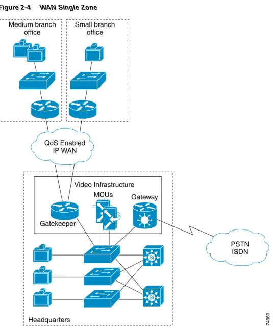
Figure 2-4 illustrates a single-zone H.323 video network in a WAN environment. This deployment model is used when remote sites have a small number of video endpoints, usually no more than one or two at each remote site on a T1 WAN link. From a management or economic standpoint, it might not make sense to create a zone at each remote site for one or two video terminals. Call admission control (CAC) across the WAN is not usually an issue with only one or two video terminals at each remote site, but it is an issue when the number of remote endpoints exceeds the provisioned video bandwidth.
In the absence of a gatekeeper, implement quality of service on the WAN ports by using one of the following methods:
• Priority queuing on traffic classification IP Precedence 4, or Differentiated Services Code Point (DSCP) AF41
• Access control list (ACL) for each video terminal at the remote site, to direct the video streams to the appropriate priority queue
Chapter 2 Deployment Models WAN Single Zone
Figure 2-4 WAN Single Zone
The WAN single-zone deployment model has the following design characteristics: • A single gatekeeper supporting a single zone for H.323 video.
• All H.323 video users registered with the single gatekeeper. (See Chapter 8 for gatekeeper registration limits.)
• Optional PSTN access available through Cisco IP/VC 352X gateway.
• Optional multipoint conferencing available through the Cisco IP/VC 3510 MCU. • H.323 video bandwidth managed by a single gatekeeper.
• All gateway and MCU services registered and managed by a single gatekeeper. • WAN QoS, with priority queuing by means of traffic classification or ACL entries. • Call routing between endpoints using fully qualified E.164 addresses or H.323-ID.
74660 Si Si MCUs Gateway Gatekeeper Medium branch office Small branch office Headquarters Video Infrastructure PSTN ISDN QoS Enabled IP WAN
Chapter 2 Deployment Models
WAN Multi Zone
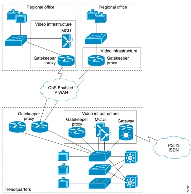
WAN Multi Zone
Figure 2-5 illustrates a multi-zone H.323 network in a WAN environment. This deployment model is used in large enterprise, government, and educational networks. QoS can be implemented using either the proxy and priority queuing (PQ) features in Cisco IOS software, traffic classification by the video terminals, or Layer 3 switches in conjunction with priority queuing on the WAN ports of the routers. Creating multiple zones in a WAN environment allows administrators to manage network resources and assure video quality across low-speed WAN links. Call admission control (CAC) is very important in a large WAN environment. With multiple zones enabled, the gatekeeper can manage the total amount of H.323 video bandwidth allowed across a particular network link. For example, you could limit the total H.323 video bandwidth across a T1 WAN link to 768 kbps, and the gatekeeper would then reject any call request that exceeds this limit of 768 kbps.
Figure 2-5 WAN Multi Zone
74661 Si Si MCUs MCU Gateway Gatekeeper proxy Gatekeeper proxy Gatekeeper proxy Regional office Video infrastructure Video infrastructure Regional office Headquarters PSTN ISDN QoS Enabled IP WAN Gatekeeper
Chapter 2 Deployment Models WAN Multi Zone
The WAN multi-zone deployment model has the following design characteristics: • Multiple gatekeepers supporting multiple zones for H.323 video.
• H.323 endpoints and services registered with the assigned gatekeeper, usually at the local site. • Optional PSTN access available through Cisco IP/VC 352X.
• Bandwidth management available in each zone and across the WAN, using the gatekeeper at each site.
• Distributed services available at larger branch sites to conserve bandwidth.
• Inter-zone and intra-zone call routing using fully qualified E.164 addresses or H.323-ID. • Proxy enabled at each site with priority queuing (PQ) on the WAN, or PQ based on traffic
C H A P T E R
3
Campus Infrastructure
This chapter provides guidelines for deploying H.323 videoconferencing with Quality of Service (QoS) on a campus network using one of the following basic H.323 video designs:
• Single-Zone Campus, page 3-2
• Multi-Zone Campus, page 3-3
Network Infrastructure
Building an end-to-end H.323 video network requires an infrastructure based on Layer 2 and Layer 3 switches and routers. It is important to have all H.323 video endpoints, gateways, and multipoint conference units (MCUs) connected to a dedicated 10/100 switched Ethernet port. Cisco recommends using a 100-Mbps full duplex connection to the Cisco gatekeeper to ensure adequate bandwidth on all router platforms. Some endpoints, however, do not support 100-Mbps full duplex. For example, older Polycom ViewStations and the Cisco IP/VC 3530 both support 10-Mbps half duplex only.
Note There are known issues with some Cisco Catalyst switches and video endpoints negotiating half/full duplex. If the negotiation fails, the endpoint still functions but the system experiences video freezing every three to five seconds. Cisco recommends that you set all switch ports attached to H.323 video devices to 100-Mbps full duplex whenever possible. If the video unit supports only 10 Mbps, configure the switch port for 10-Mbps half duplex.
Chapter 3 Campus Infrastructure Single-Zone Campus
Single-Zone Campus
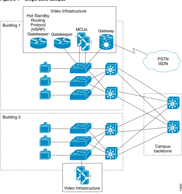
Figure 3-1 illustrates an H.323 single-zone campus network.
Figure 3-1 Single-Zone Campus
Single-zone campus networks are usually used in pilot deployments or in campuses with a small number of video terminals or endpoints. The single-zone campus deployment allows an administrator to deploy H.323 video on the campus while keeping management overhead to a minimum. There is only one gatekeeper to manage, and the dial plan is very simple with no inter-zone call routing.
It is important to consider multi-zone dial plans when deploying a single-zone model. If you deploy a single-zone dial plan but need to upgrade to a multi-zone model in the future, you will have to change the entire dial plan. Therefore, to simplify future network scaling, Cisco recommends that you use a multi-zone dial plan even for a single-zone campus.
Si Si Campus backbone 74662 Si Si MCUs Gateway Gatekeeper Hot Standby Routing Protocol (HSRP) Gatekeeper Video Infrastructure PSTN ISDN Buidling 1 Si Si Building 2 Video Infrastructure
Chapter 3 Campus Infrastructure
Multi-Zone Campus
In summary, a single-zone campus model consists of: • Campus environment
• Pilot environments
• Small number of video endpoints • No bandwidth limitations
Multi-Zone Campus
Figure 3-2 illustrates an H.323 multi-zone campus network.
Figure 3-2 Multi-Zone Campus
Multi-zone campus networks are common in large campus environments. Creating multiple zones allows administrators to segment user groups for security, better management of the H.323 video network, and bandwidth control in and between zones. For example, company executives may be registered in a single zone containing their own gateway and MCU resources.
Si Si Campus backbone 74663 Si Si MCUs Gateway Gatekeeper Gatekeeper Zone 1 Zone 2 PSTN ISDN Si Si
Chapter 3 Campus Infrastructure Quality of Service
In campuses with a large number of video terminals, it is important to control the amount of video bandwidth on the network. With a single zone, bandwidth management capabilities are very limited. Creating multiple logical zones on the campus allows an administrator to manage bandwidth within and between zones.
Physical placement of gatekeepers, MCUs, and gateways depends on customer preference and network configuration. Some deployments locate all of the gatekeepers, MCUs, and gateways in a single data center, while others may decide to distribute the equipment throughout the campus.
In summary, the multi-zone campus model consists of: • Campus environment
• Large numbers of video terminals
• Users segmented into separate video domains • Restricted access for some users
Note Multiple zones can be configured on a single router. If you configure multiple local zones on a single router, you must add hopoff commands for each service prefix registered. If hopoffs are not added for each service prefix, the video terminal will not be able to access MCUs or gateways outside its local zone. See Routing Inter-Zone Calls Using Hopoff Statements, page 7-8 for more information.
Quality of Service
In a converged environment, voice, video and data traffic all travel over a single transport infrastructure. Not all traffic types should be treated equally. Data traffic is bursty, loss tolerant, and not sensitive to delay. Video traffic, on the other hand, is bursty, has very little tolerance for loss, and is latency sensitive. The challenge is to provide the required level of service for all three traffic types.
Running both video and data on a common network requires the proper QoS tools to ensure that the delay and loss parameters of video traffic are satisfied in the face of unpredictable data flows. Some of these tools may be available as a feature in some video terminals (for example, Polycom, VCON, and PictureTel), switches, and routers.
Traffic Classification Types
The first step in preserving video quality on a data network is to classify video traffic as high priority and allow it to travel through the network before lower priority traffic. Data traffic can be classified at a lower priority without adversely affecting its performance because of its characteristics as provided by the Transfer Control Protocol (TCP), which handles flow control and error correction. For video, classify traffic at Layer 2 and Layer 3 as follows:
• At Layer 2, use the three bits in the 802.1Qp field, referred to as class of service (CoS), which is part of the 802.1Q tag.
• At Layer 3, use the three bits of the Differentiated Services Code Point (DSCP) field in the type of service (ToS) byte of the IP header.
Traffic classification is the first step toward achieving QoS. Ideally, you should perform this step as close to the source as possible. However, you can also set this field within a router using the Cisco Multimedia Conference Manager (MCM), a Cisco IOS feature.
Chapter 3 Campus Infrastructure
Quality of Service
Trust Boundaries
The concept of trust is an important and integral part of deploying QoS. Once the end devices have set ToS values, the switch has the option of trusting them or not. If the switch trusts the ToS values, it does not need to do any reclassification; if it does not trust the values, then it must reclassify the traffic for appropriate QoS.
The notion of trusting or not trusting forms the basis for the trust boundary. Ideally, traffic classification should be done as close to the source as possible. If the end device is capable of performing traffic classification, then the trust boundary for the network is at the access layer in the wiring closet. If the device is not capable of performing traffic classification, or if the wiring closet switch does not trust the classification done by the end device, the trust boundary should shift to other devices.
Shifting of the trust boundary depends on the capabilities of the switch in the wiring closet. If the switch can reclassify the packets, then the trust boundary remains in the wiring closet. If the switch cannot perform this function, then the task falls to other devices in the network going toward the backbone. In this case, reclassification occurs at the distribution layer, which means that the trust boundary has shifted to the distribution layer. For this shift to occur, there must be a high-end switch in the distribution layer with features to support traffic reclassification. If possible, try to avoid performing traffic reclassification in the core of the network.
In summary, try to maintain the trust boundary in the wiring closet. If necessary, move it down to the distribution layer on a case-by-case basis, but avoid moving it to the core of the network. This advice conforms to the general guidelines for keeping the trust boundary as close to the source as possible.
Note This discussion assumes a three-tier network model, which has proven to be a scalable architecture. If the network is small and the logical functions of the distribution layer and core layer happen to be in the same device, then the trust boundary can reside in the core layer if it has to move from the wiring closet. For detailed configuration information, refer to the Cisco AVVID Network Infrastructure Enterprise
Quality of Service Design guide.
Table 3-1 Recommended Traffic Classifications
Layer 2 Layer 3 Classification
Application CoS IP Precedence Pre-Hop Behavior (PHB) DSCP
7 7 – 56-63 Reserved
6 6 – 48-55 Reserved
5 5 EF 46 Voice Bearer
4 4 AF41 34 Video Conferencing
3 3 AF31 26 Call Signaling
2 2 AF2y 18, 20, 22 High Priority Data
1 1 AF1y 10, 14, 16 Medium Priority Data
Chapter 3 Campus Infrastructure Quality of Service
QoS Features Summary
Table 3-2 shows supported QoS features on each switch platform.
Note Currently the only Cisco LAN switches that support a minimum of two queues and that can guarantee video quality are the Catalyst 8500, Catalyst 6000 family, Catalyst 4000 family, Catalyst 3500XL, and Catalyst 2900XL.
In summary, follow these recommendations for QoS deployment:
• Create a trust boundary at the network edge in the wiring closet. Enable the trust boundary on ports on the wiring closet switch where video terminals have the ability to set IP precedence. A rule of thumb is to trust the classification from conference room systems and not trust classification from desktop video units.
• Reclassify ToS at the edge if devices (both room systems and desktop units) cannot be trusted. • Shift the trust boundary to the distribution layer and reclassify ToS there if reclassification is not
possible at the edge.
• Use a priority queue for delay-sensitive video traffic.
Table 3-2 Supported QoS Features by Switch Platform
Platform Ability to Trust Reclassify CoS Reclassify ToS Congestion Avoidance (WRED)1
1. Weighted random early detection (WRED).
Priority Queues Multiple Queues Congestion Management (WRR)2
2. Weighted round robin (WRR).
Policing
Catalyst 2900XL No Yes No No No Yes No No
Catalyst 2950 Yes Yes Yes Yes Yes Yes Yes Yes
Catalyst 3500XL and 3524-PWR-XL
Yes Yes No No Yes Yes Yes No
Catalyst 3550 Yes Yes Yes Yes Yes Yes Yes Yes
Catalyst 4000 with Supervisor Engine II Yes Yes (Switch- wide) No No No Yes No No Catalyst 4006 with Supervisor Engine II Yes Yes (Switch- wide) No No No Yes No No Catalyst 4006 with Supervisor Engine III
Yes Yes Yes Yes Yes Yes Yes Yes
Catalyst 5000 Yes Yes Yes Yes (Does not work for VoIP on bottom threshold)
Yes Yes No Yes
Catalyst 6000 with Policy Feature Card (PFC)
C H A P T E R
4
WAN Infrastructure
This chapter provides guidelines for deploying H.323 video across an IP WAN, and it describes IP WAN infrastructure design considerations for:
• Single-Zone WAN, page 4-2
Chapter 4 WAN Infrastructure Single-Zone WAN
Single-Zone WAN
Figure 4-1 illustrates a single-zone WAN network.
Figure 4-1 Single-Zone WAN
A single-zone WAN model consists of the WAN environment and less than three videoconferencing terminals per remote site. (This limit is based on a T1 WAN link.) Cisco recommends that you configure a gatekeeper and a zone for a remote site with one or two video terminals, but this configuration is not strictly required. 74664 Si Si MCUs MCU Gateway Video infrastructure Medium branch office Video infrastructure Small branch office Headquarters PSTN ISDN QoS Enabled IP WAN Gatekeeper
Chapter 4 WAN Infrastructure
Single-Zone WAN
Due to the limited number of endpoints and traffic classification options, you can achieve quality of service (QoS) and call admission control (CAC) by following these basic rules:
• The total data rate of the video terminals plus 20% should not exceed 33% of the WAN link capacity. • The priority queue must be provisioned for the maximum data rate of the video terminals plus 20%. For example, assume a site has a link capacity of 1.544 Mbps and contains two video terminals that support a maximum data rate of 256 kbps each. Therefore, the required queue size for the two video terminals is (256+256)x120% = 614 kbps. Provisioning the priority queue for 614 kbps allows both video terminals to be in a call across the WAN at the same time, without the possibility of
overrunning the priority queue. If we add a third video terminal in this example, we would need to add a gatekeeper and create a zone to provide call admission control.
The key elements for successful deployment of videoconferencing in a single-zone WAN environment are:
• Traffic Classification, page 4-3
• Call Admission Control (CAC), page 4-4
• Provisioning, page 4-4
• Priority Queuing on the WAN, page 4-4
• Entrance Criteria, page 4-4
Traffic Classification
Classify traffic at one of the following places:
• Video endpoint (Polycom, PictureTel, Tandberg, and VCON); IP Precedence 4 or DSCP AF41 • Switch port (Layer 3 switch required); IP Precedence 4 or DSCP AF41 (recommended) • Router (ACL entry); IP Precedence 4 or DSCP AF41
Figure 4-2 illustrates these three options for traffic classification.
Figure 4-2 Traffic Classification Options for Single-Zone WAN
74665 QoS Enabled IP WAN H.323 Video endpoint H.323 Video endpoint Option 1: Set IP precedence 4: Polycom VCON PictureTel Tandberg Option 2:
ACL on switch port (layer3 switch) assigning IP precedence 4/DSCP AF41
Option 3:
ACL on router setting IP precedence 4/DSCP AF41 and mapping to the correct PQ
Chapter 4 WAN Infrastructure Single-Zone WAN
Call Admission Control (CAC)
For remote sites that do not have a gatekeeper to enforce CAC, provision the priority queue and limit the number of video terminals at each site. The number of video terminals multiplied by the maximum call data rate, must not exceed the capacity of the priority queue. Cisco recommends that you use a gatekeeper and zones for remote sites with more than two video terminals. You can install a gatekeeper at each remote site with more than two video terminals, or you can install one gatekeeper at the central site and define a separate zone for each remote site.
Note This recommendation is based on a T1 WAN link.
Provisioning
Provision WAN queues according to the following equation:
Priority queue size = (Number of users) x (Maximum data rate of video terminals) x 120% The priority queue must be provisioned to handle the maximum data rate used by any of the video terminals, otherwise the priority queue has the potential to become oversubscribed. Add 20% to the maximum data rate of the video terminals to allow for IP and transport overhead. Refer to the WAN QoS
chapter for more information.
Priority Queuing on the WAN
Configure multiple queues for the WAN ports on routers. Videoconferencing traffic goes into a priority queue (PQ) that services IP Precedence 4 or DSCP AF41. Class-based weighted fair queuing (CBWFQ) is not recommended for interactive video.
Entrance Criteria
In the single-zone WAN model, use access control lists (ACLs) to access configured priority queues at remote sites. ACLs ensure that only traffic from the video terminals has access to the configure PQ. The small number of video terminals at remote sites makes ACL entries a viable option.
Central sites that have either Layer 3 switches or video terminals capable of setting IP Precedence, should set the entrance criteria for the PQ to any packets with IP Precedence 4 or DSCP AF41. This method, however, is not as secure as the ACL option but works properly if the trust boundaries are configured correctly. This method can also be used at remote sites if ACLs are not acceptable.
Chapter 4 WAN Infrastructure
Multi-Zone WAN
Multi-Zone WAN
Figure 4-3 illustrates a multi-zone WAN network.
Figure 4-3 Multi-Zone WAN
A multi-zone WAN model consists of the WAN environment and three or more videoconferencing terminals per remote site. (This model is based on a T1 WAN link.) Multi-zone WAN deployments are found in large enterprises and state-based distance-learning networks. Remote sites containing three or more video terminals are managed by either a centralized or local gatekeeper (local gatekeeper is recommended). The gatekeeper manages bandwidth within the local zone and across the WAN between zones.
Currently, it is possible to manage bandwidth only in a hub-and-spoke environment with gatekeeper bandwidth controls. An intermediate gatekeeper is not aware of a call passing through its zone. Only the originating zone gatekeeper and terminating zone gatekeeper are aware of the active call. Resource Reservation Protocol (RSVP) can be used in conjunction with Differentiated Services Code Point
74666 Si Si MCUs MCU Gateway Gatekeeper proxy Gatekeeper proxy Gatekeeper proxy Gatekeeper proxy Regional office Video infrastructure Video infrastructure Video infrastructure Regional office Headquarters PSTN ISDN QoS Enabled IP WAN
Chapter 4 WAN Infrastructure Multi-Zone WAN
(DSCP) to scale larger than hub-and-spoke environments. This configuration may, however, cause issues with other applications such as IP telephony. See the appendix on Resource Reservation Protocol (RSVP) for more information.
Figure 4-3 shows each remote site running the gatekeeper and proxy on the WAN router, and dedicated routers running Hot Standby Routing Protocol (HSRP) for the gatekeeper and proxy at the central site. Two factors determine whether to use a dedicated router or a shared router for the gatekeeper and proxy: • Is the site currently running the appropriate router software for gatekeeper and proxy support? If not,
either upgrade the router software or use a dedicated router for the gatekeeper and proxy. • What is the number of registered endpoints and simultaneous calls being processed? If there are
more than 20 registered endpoints at a given site, Cisco recommends using a dedicated router. For registration numbers and CPU utilization, refer to the chapter on Cisco Video Infrastructure Components.
The deployment guidelines for a multi-zone WAN environment are similar to those for a single-zone WAN. The biggest difference is the ability to control bandwidth in the multi-zone WAN through an added classification point (gatekeeper and zone). The key elements for successful deployment of videoconferencing in a multi-zone WAN environment are:
• Traffic Classification, page 4-7
• Bandwidth Control and Call Admission Control (CAC), page 4-7
• Provisioning, page 4-7
• Priority Queuing on the WAN, page 4-8
Chapter 4 WAN Infrastructure
Multi-Zone WAN
Traffic Classification
Classify traffic at one of the following places:
• Video endpoint (Polycom, PictureTel, Tandberg, and VCON); IP Precedence 4 or DSCP AF41 • Proxy classification; IP Precedence 4 or RSVP (recommended for traffic reclassification)
• Switch port (Layer 3 switch required); IP Precedence 4 or DSCP AF41 (recommended classification method for all video endpoints)
• Router (ACL entry); IP Precedence 4 or DSCP AF41 (Due to the larger number of video terminals at each site, this option is not typically used.)
Figure 4-4 illustrates classification options for a multi-zone WAN model.
Figure 4-4 Traffic Classification Options for Multi-Zone WAN
Bandwidth Control and Call Admission Control (CAC)
Because each remote site in a multi-zone WAN has its own gatekeeper and zone, bandwidth control between zones is possible. By configuring the remote bandwidth in each remote gatekeeper,
administrators can limit the amount of available bandwidth for calls to and from the WAN. Use the global bandwidth remote command at remote sites to control video calls across WAN links. For more information on the gatekeeper and bandwidth control, refer to the chapter on Cisco Video Infrastructure Components.
Provisioning
Provision WAN queues based on the bandwidth limits set in the gatekeeper, and do not provision more than 33% of the link capacity for voice and video applications. Cisco recommends that voice and video traffic combined use no more than 33% of the link capacity.
74667 QoS Enabled IP WAN H.323 Video endpoint Gatekeeper proxy H.323 Video endpoint Option 1: Set IP precedence 4: Polycom VCON PictureTel Tandberg Option 3:
ACL on switch port (layer3 switch) assigning IP precedence 4/DSCP AF41
Option 2:
Proxy to classify traffic IP precedence 4 or RSVP. Single entrance point to the priority queue.
Option 4:
ACL on router setting IP precedence 4/DSCP AF41 and mapping to the correct PQ
Chapter 4 WAN Infrastructure Multi-Zone WAN
Priority Queuing on the WAN
Configure multiple queues for WAN ports on routers. Videoconferencing traffic goes into a PQ that services the proxy only, or streams marked with IP Precedence 4 or DSCP AF41.
Entrance Criteria
Using the proxy allows administrators to limit access to the priority queue by configuring an ACL on the WAN router. Only video calls authenticated by the gatekeeper have access to the proxy. The ACL allows only packets received from the proxy to access the configured priority queue. The ACL prevents unauthorized users from installing a video terminal on their desk, making video calls using IP addresses, and accessing the priority queue. By restricting access to the priority queue, the configured ACL ensures that unauthorized users cannot oversubscribe the priority queue. Rouge users are serviced out of the default queue, thus ensuring video quality for authorized video terminals.
If the proxy is not used, the entrance criteria for the priority queue should be any packets with IP Precedence set to 4 or DSCP AF41. It is important to configure trust boundaries properly to prevent unauthorized traffic from accessing the priority queue.
C H A P T E R
5
WAN QoS
This chapter addresses quality of service (QoS) requirements for implementations of H.323 videoconferencing solutions over the enterprise WAN. By applying the prerequisite tools, you can achieve excellent video, voice, and data transmissions over an IP WAN, irrespective of media and even low data rates.
WAN QoS Model
Figure 5-1 illustrates the typical hub-and-spoke topology of the enterprise WAN model described in this chapter.
Figure 5-1 Enterprise WAN Model
74668 QoS Enabled IP WAN Cisco 3600 Gatekeeper/proxy Cisco 2600 Gatekeeper/proxy Regional HQ office Cisco 7200 Cisco 2600 Gatekeeper/proxy Cisco 3600 Gatekeeper/proxy
Chapter 5 WAN QoS Capacity Planning
Capacity Planning
Before placing video traffic on a network, ensure that adequate bandwidth exists for all required applications. First, calculate the minimum bandwidth requirements for each major application (for example, voice, video, and data). This sum represents the minimum bandwidth requirement for any given link, and it should consume no more than 75% of the total bandwidth available on that link. This 75% rule assumes that some bandwidth is required for overhead traffic, such as routing and Layer 2 keepalives, as well as additional applications such as email and HyperText Transfer Protocol (HTTP) traffic. Figure 5-2 illustrates capacity planning on a converged network.
Figure 5-2 Capacity Planning on a Data, Voice, and Video Network
QoS Tools
This section discusses the tools used to implement QoS for H.323 videoconferencing over an enterprise WAN. These tools include:
• Traffic Classification, page 5-3
• Proxy Usage, page 5-3
• Traffic Prioritization, page 5-3
This section concludes with a summary of best practices for each of the applicable data link protocols.
Video Voice Data Routing etc.
< 33% of link capacity 128kbps = 153kbps 384kbps = 460kbps 512kbps = 614kbps 768kbps = 921kbps 1.5Mbps = 1.8Mbps Video data rate
BW required Video data rate + 20% = bandwidth required
< 75% of link capacity
Link capacity
Chapter 5 WAN QoS
QoS Tools
Traffic Classification
Before traffic can be handled according to its unique requirements, it must be identified or labeled. There are numerous classification techniques, including Layer 3 schemes such as IP Precedence or
Differentiated Services Code Point (DSCP).
In many cases, traffic classification is done at the edge of the network by the video terminal or an Ethernet switch such as the Catalyst 6000. In these cases, the trust boundary is extended to the edge of the enterprise network and resides in the access or distribution layer. For a more detailed discussion of trust boundaries, see Trust Boundaries, page 3-5.
In some cases, however, the ability to classify and define a trust boundary at the edge of the network might not exist, such as in a branch with Ethernet switches and video endpoints that cannot classify traffic. In this situation, you can implement the trust boundary and classification on the router itself by using ACL entries for small sites without a gatekeeper or by using the proxy in larger branch sites that contain a gatekeeper.
Proxy Usage
In the multi-zone WAN model, Cisco recommends that you use the proxy whenever possible. The proxy allows the classification or reclassification of video streams with IP Precedence or Resource Reservation Protocol (RSVP). The proxy also provides a single access point for the priority queue to keep
unauthorized video streams from oversubscribing the priority queue. Video terminals must be registered with the gatekeeper to obtain access to the proxy. The gatekeeper is configured for a maximum video bandwidth allowed outside its local zone. This maximum bandwidth should match the amount of bandwidth provisioned for the priority queue to ensure proper queuing functionality.
Traffic Prioritization
In choosing from among the many available prioritization schemes, the major factors to consider include the type of traffic being put on the network and the wide area media being traversed. For multi-service traffic over an IP WAN, Cisco recommends low-latency queuing for the WAN. This allows up to 64 traffic classes, with the ability to use multiple queues for different traffic types, such as priority queuing behavior for videoconferencing and voice, a minimum bandwidth for Systems Network Architecture (SNA) data and market data feeds, and weighted fair queuing for other types of traffic.
Figure 5-3 shows this prioritization scheme as follows:
• Video traffic is placed into a queue with priority queuing (PQ) capabilities and is allocated a bandwidth of 460 kbps. The entrance criterion for this queue could be any video stream received from the specific IP address of a proxy or any traffic with IP Precedence set to 4. Traffic in excess of 460 kbps would be dropped if the interface becomes congested. Therefore, an admission control mechanism (such as gatekeeper bandwidth limits) must be used to ensure that this limit is not exceeded.
• SNA traffic is placed into a queue that has a specified bandwidth of 56 kbps. Queuing operation within this class is first-in-first-out (FIFO) with a maximum allocated bandwidth of 56 kbps. Traffic in this class that exceeds 56 kbps is placed in the default queue. The entrance criterion for this queue could be Transmission Control Protocol (TCP) port numbers, Layer 3 address, IP Precedence, or DSCP.
• All remaining traffic can be placed in a default queue. If you specify a bandwidth, the queuing operation is FIFO. Alternatively, if you specify the keyword fair, the queuing operation is weighted fair queuing (WFQ).
Chapter 5 WAN QoS QoS Tools
Figure 5-3 illustrates optimized queuing for videoconferencing on the WAN.
Figure 5-3 Optimized Queuing
Keep in mind the following points when configuring low-latency queuing:
• For leased lines and Asynchronous Transfer Mode (ATM), the minimum system software is Cisco IOS Release 12.0(7) T.
• For Frame Relay, the minimum system software is Cisco IOS Release 12.1(2) T.
Table 5-1 gives the minimum bandwidth requirements for video and data networks. Note these values are minimum, and any network should be engineered with adequate capacity for all the applications that will use it.
74670 Transmit ring Video (PQ460k) Data-SNA (SNA FIFO 56k) Data default (FIFO or WFQ) 1 1 2 2 2 3 2 1 1 3 3 3
Table 5-1 Minimum Bandwidth Requirements
Traffic Type Leased Lines Frame Relay ATM
ATM Over Frame Relay Video + Data
Maximum video data rates up to 384 kbps
768 kbps 768 kbps 768 kbps 768 kbps
Video + Data
Maximum video data rates > 384 kbps