Hemp Fibre Reinforced Sheet Moulding Compounds
Patel, HarishThe copyright of this thesis rests with the author and no quotation from it or information derived from it may be published without the prior written consent of the author
For additional information about this publication click this link. http://qmro.qmul.ac.uk/jspui/handle/123456789/8783
Information about this research object was correct at the time of download; we occasionally make corrections to records, please therefore check the published record when citing. For more information contact [email protected]
Hemp Fibre Reinforced Sheet
Moulding Compounds
Harish Patel
School of Engineering and Materials Science
Queen Mary University of London
A thesis submitted for the degree of
Doctor of Philosophy
I would like to dedicate this thesis to my loving parents Narmada and Shantilal Patel
Acknowledgements
First and foremost, I would like to thank my supervisor Prof Ton Peijs for his always insightful suggestions and expert guidance. His unwavering commitment to his students and constant demand for ex-cellence really helped me bring this work to fruition. It has been a privilege and memorable experience to work with Ton.
Secondly, I would like to express my sincere appreciation to Prof. Paul Hogg and Dr Guogang Ren for their support and guidance and initiating this inter-disciplinary project.
I would like to express my gratitude to Building Research Establish-ment (BRE) and Engineering and Physical Sciences Research Council (EPSRC) for funding that made this research possible. Thanks also to Dr. Mizi Fan (BRE) for his help and assistance. I am also grateful to Menzolit Lt. (Lancashire, UK) for allowing us to use the SMC equip-ment and providing the raw materials. The help and assistance in the preparation of the composites, as well as stimulating discussions with Mr Steve Crowther are also gratefully acknowledged. I acknowledge Mr John Hobson, Hemcore Ltd (Halesworth, UK) for providing the hemp fibre mats used in the present study.
I am thankful to Queen Mary University of London (QMUL), UK, for providing all the facilities and a friendly environment, which helped me to work with all the colleagues peacefully and enthusiastically. I appreciate QMUL for organising presentations, poster sessions and other activities, which showed active involvement of QMUL towards the completion of the project.
I would like to express my sincere appreciation to the staff and tech-nicians at QMUL for helping full-heartedly during the project. I am
also grateful to all the graduate students and colleagues who helped me during the project. Some of them are Dhanushka Hapuarachchi, Vimalan Balasubramaniam, Anjum Malhotra and Dawei Hu. I would like to thank workshop staff in the School of Engineering and Materi-als Science for helping and designing some of the apparatus used for the study.
Words cannot express my gratitude towards my parents (Mr. Shan-tilal Patel and Mrs. Narmada Patel), wife (Neha Patel), brother and sister-in-law (Kishor and Manisha Patel), sister and brother-in-law (Pushpa and Jignesh Patel), nieces (Krishi and Nancy) for their love, moral support and encouragement during this study. Finally, I would like to acknowledge all my teachers who taught me directly or indi-rectly.
Abstract
Glass fibres are by far the most extensively used fibre reinforcement in thermosetting composites because of their excellent cost-performance ratio. However, glass fibres have some disadvantages such as non-renewability and problems with ultimate disposal at the end of a materials lifetime since they cannot be completely thermally incin-erated. The possibility of replacing E-glass fibres with hemp fibres as reinforcement in sheet moulding compounds (SMC) is examined in this thesis. The composites are manufactured with existing SMC processing techniques and similar resin formulation as used in the commercial industry. An attempt is made to enhance/optimise the mechanical properties of hemp/polyester composites. For this the fibre-matrix interface is modified via chemical modifications with al-kaline and silane treatments.
Influence of hemp fibre volume fraction, calcium carbonate (CaCO3)
filler content and fibre-matrix interface modification on the mechani-cal properties of hemp fibre-mat-reinforced sheet moulding compounds (H-SMC) is studied. The results of H-SMC composites are compared to E-glass fibre-reinforced sheet moulding compounds (G-SMC). In order to get a better insight in the importance of these different pa-rameters for the optimisation of composite performance, the experi-mental results are compared with theoretical predictions made using modified micromechanical models such as Cox-Krenchel and Kelly-Tyson for random short-fibre-reinforced composites. These models are supplemented with parameters of composite porosity to improve the prediction of natural fibre composite tensile properties.
The influence of impact damage on the residual flexural strength of the H-SMC composites is investigated to improve the understanding
of impact response of natural fibre reinforced composites. The result of penetration and absorbed energies during non-penetrating impact of H-SMC composites are investigated and compared to values for G-SMC. A simple mechanistic model has been developed for H-SMC composites and is used to get an insight into the impact behaviour of these composite as well as to provide a guideline to compare the experimental results with theoretically calculated data.
The fracture toughness properties in terms of the critical-stress-intensity factor KIc, and critical strain energy release rate, GIc, of H-SMC and G-SMC composites are studied using the compact tension (CT) method. It was shown that fracture toughness of H-SMC composites is significantly lower than that of glass fibre reinforced composites (G-SMC). However, results show that with an optimum combination of fi-bre volume fraction, (CaCO3) filler and surface treatment of the hemp
fibres can result in H-SMC composites that have fracture toughness properties that can be exploited for low to medium range engineering applications. It is recommended that to further improve the fracture toughness properties of these natural fibre reinforced composites more research needs to be devoted to the optimization of the fibre-matrix interface properties and ways of reducing porosity content in these composites.
Finally, environmental impact of H-SMC composite with conventional G-SMC composite for automotive and non-automotive applications was compared. The composites were assumed to be made in a tra-ditional SMC manufacturing method. Two different types of perfor-mance requirements; i.e. stiffness and strength were investigated for both the non-automotive and automotive parts. Two different dis-posal scenarios: landfill and incineration of the SMC product at the end of life was considered. The LCA results demonstrate that the environmental impact of H-SMC composites is low than the reference G-SMC composites. G-SMC composites have a significantly higher environmental impact on climate change, acidification and fossil fuels
than H-SMC composites. Where as H-SMC composites have a much higher impact on land use and ecotoxicity than G-SMC composites.
Contents
Contents vii
List of Figures xii
List of Tables xx
Nomenclature xxi
1 Introduction 1
1.1 Thermosetting composites . . . 3
1.2 Processing of thermosetting composites . . . 6
1.3 Thermosetting composite reinforcements . . . 10
1.4 Natural fibre composites: an introduction . . . 12
1.5 Natural fibre composites: present & future applications . . . 13
1.6 Natural fibre composites: barriers & challenges . . . 16
1.7 Research partners . . . 17
1.8 Aims & Objectives . . . 18
1.9 Structure of this thesis . . . 18
2 Natural fibres 21 2.1 Classification of natural fibres . . . 21
2.2 Natural fibre composition . . . 22
2.3 Structure of a single natural fibre . . . 27
2.4 Physical & mechanical properties . . . 28
2.5 History of hemp . . . 32
CONTENTS
2.7 Hemp structure: from plant to fibre . . . 34
2.8 Hemp fibre processing . . . 37
2.8.1 Cultivation & harvesting . . . 39
2.8.2 Retting . . . 40
2.8.3 Breaking & scutching . . . 41
2.8.4 Hackling . . . 43
2.9 Processing of non-woven natural fibre mat . . . 44
2.10 Mechanical properties of non-woven natural fibre composites . . . 49
2.11 Summary . . . 51
3 Mechanical properties of hemp fibre reinforced SMC composites 52 3.1 Introduction . . . 52
3.2 Experimental . . . 57
3.2.1 Materials . . . 57
3.2.2 Fibre surface treatment . . . 57
3.2.3 Composite fabrication . . . 58
3.2.4 Tensile testing . . . 59
3.3 Micromechanical modelling . . . 60
3.4 Results and Discussion . . . 62
3.4.1 Fibre morphology . . . 62
3.4.2 Influence of fibre content on mechanical properties . . . 64
3.4.2.1 Tensile strength . . . 64
3.4.2.2 Tensile modulus . . . 67
3.4.3 Influence of CaCO3 content on mechanical properties . . . 69
3.4.4 Influence of hemp fibre surface treatment . . . 72
3.4.4.1 Alkaline treatment . . . 73
3.4.4.2 Silane treatment . . . 74
3.4.4.3 Alkaline-Silane treatment . . . 74
3.4.5 Fracture surface analysis . . . 74
3.5 Conclusions . . . 76
4 Impact properties of hemp fibre reinforced SMC composites 78 4.1 Introduction . . . 78
CONTENTS
4.1.1 Low velocity impact . . . 79
4.1.2 Damage modes in random fibre composites . . . 79
4.1.3 Low velocity impact test methods . . . 80
4.1.4 Data interpretation . . . 82
4.1.5 Impact studies on natural fibre composites . . . 85
4.2 Experimental . . . 86
4.2.1 Impact testing . . . 86
4.3 A simple mechanistic model to predict penetration energy . . . . 87
4.4 Results and Discussion . . . 89
4.4.1 Impact event characteristics . . . 89
4.4.2 Influence of fibre volume fraction . . . 90
4.4.3 Influence of CaCO3 filler content . . . 93
4.4.4 Influence of fibre surface treatment . . . 96
4.4.4.1 Alkaline treatment . . . 96
4.4.4.2 Silane treatment . . . 98
4.4.4.3 Alkaline-Silane treatment . . . 98
4.4.5 Damage charateristics . . . 98
4.5 Conclusions . . . 99
5 Post-impact damage and flexural properties of hemp fibre rein-forced SMC composites 101 5.1 Introduction . . . 101 5.2 Residual strength . . . 102 5.2.1 Residual strength of NFCs . . . 102 5.3 Experimental . . . 104 5.3.1 Impact testing . . . 104
5.3.2 Residual flexural strength . . . 104
5.4 Results and Discussion . . . 105
5.4.1 Influence of fibre volume fraction . . . 105
5.4.1.1 Impact characteristics . . . 105
5.4.1.2 Energy profile . . . 108
5.4.1.3 Damage development . . . 110
CONTENTS
5.4.2 Influence of fibre surface treatment . . . 115
5.4.2.1 Energy profile . . . 115
5.4.2.2 Post-impact flexural properties . . . 116
5.5 Conclusions . . . 119
6 Fracture toughness of hemp fibre reinforced SMC composites 120 6.1 Introduction . . . 120
6.2 Fracture mechanics . . . 121
6.2.1 The energy balance approach . . . 122
6.2.2 The stress approach . . . 123
6.2.3 Fracture toughness testing . . . 126
6.3 Fracture toughness of NFCs . . . 128
6.4 Experimental . . . 129
6.4.1 Specimens preparation and experimental setup . . . 129
6.4.2 Data analysis . . . 131
6.5 Results and Discussion . . . 132
6.5.1 Fracture characteristics . . . 132
6.5.2 Influence of fibre volume fraction . . . 133
6.5.3 Influence of CaCO3 filler content . . . 137
6.5.4 Influence of fibre surface treatment . . . 138
6.6 Conclusions . . . 141
7 Environmental impact of hemp fibre reinforced SMC composites143 7.1 Introduction . . . 143
7.1.1 LCA of natural fibre composites . . . 146
7.1.2 LCA methodology . . . 147
7.1.3 LCA drawbacks . . . 150
7.2 Materials and Methods . . . 151
7.2.1 Goal and scope . . . 151
7.2.2 Functional unit and system boundaries . . . 152
7.2.3 Raw materials . . . 154
7.2.4 Composite fabrication . . . 156
CONTENTS
7.2.6 Life cycle assessment methods . . . 158
7.2.7 Waste phase . . . 162
7.3 Results and discussions . . . 163
7.3.1 Non-automotive applications . . . 163
7.3.2 Automotive applications . . . 168
7.4 Conclusions . . . 172
8 General Conclusions and Future Work 174 8.1 Summary of results . . . 176
8.2 Direction for future work . . . 180
Appendix A: Fibre surface treatment 183
Appendix B: Fibre volume fraction 185
Appendix C: Hemp fibre properties 186
Appendix D: K fitting parameter 187
Appendix E: Weight of H-SMC and G-SMC for tensile strength and
modulus 189
Appendix F: Values for classification chart 193
Appendix G: Economic feasibility of NFCs composites 195
List of Figures
1.1 Characterisation of composite materials. . . 2
1.2 Characterisation of polymeric materials. . . 2
1.3 Schematic of the chemical reaction to form polyester. . . 4
1.4 Schematic showing the polymerising of a linear polyester resin to form a complex three-dimensional structure of a thermoset polyester resin. . . 5
1.5 Rear boot of a car made of sheet moulding compounds with carbon fibre as the reinforcing agent. . . 6
1.6 The production process for SMC sheets. . . 8
1.7 Picture of glass fibre SMC prepregs. . . 9
1.8 Schematic of SMC prepreg loading into a compression press. . . . 10
1.9 Various car components that are made of flax fibre reinforced polypropylene for a Mercedes car (Photo courtesy of Daimler Chrysler AG). . . 14
1.10 Some example of natural fibre composite applications. . . 15
2.1 Classifications of fibre according to origin. . . 23
2.2 Structured formula of cellulose [Lu et al., 1999]. . . 24
2.3 Structural formula of hemicellulose (courtesy Sigma-Aldrich). . . . 25
2.4 Structural formula of lignin [Adler, 1977]. . . 26
2.5 Cross-section of a hemp fibre (Courtesy of DoITPoMS Teaching and Learning Packages, University of Cambridge). . . 28
2.6 Schematic picture of a technical and elementary (fibre cell) flax fibre [van den Oeveret al.,2000]. . . 31
LIST OF FIGURES
2.8 Pictures of a hemp plant and leaf grown for hemp fibre. . . 35
2.9 Schmatic cross-section of hemp stem [Pakarinen, 2012]. . . 36
2.10 Photographs of a cross-section of a flax stem. (left) The white arrows show the bast fibres. The scale bar represents 0.1 mm. (right) The white arrows show spots where the interfibre bonding within the bundle is virtually absent, the grey arrows show the individual elementary fibre. The scale bar represents 50 µm [Bos, 2004]. . . 37
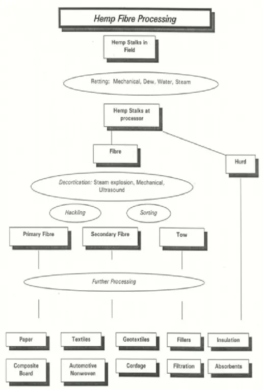
2.11 Flowchart showing the processing steps involved in obtaining var-ious forms of hemp fibre materials from the plant. . . 38
2.12 Picture of harvesting of hemp fibre using a combine harvester (Photo courtesy of Manitoba Agriculture-Food and Rural, Man-itoba, Canada). . . 39
2.13 Picture showing dew retting of hemp in the field (Photo courtesy of Henfaes Research Centre, University of Bangor). . . 41
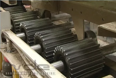
2.14 Example of breaking machine, the hemp stems are fed between the rollers. . . 42
2.15 Example of scutching turbines [Bos, 2004]. . . 43
2.16 Traditional flax fibre isolation methods and their respective prod-ucts [Bos,2004], side products of the rippling process are chaff and ripple waste (240 kg), the weight loss during retting is due to the loss of water soluble components, the rest of the weight loss is due to the loss of dust. . . 44
2.17 Needle punching process [Kamath et al., 2004]. . . 45
2.18 An example of a needle punching machine. . . 45
2.19 Needle loom [Kamath et al.,2004]. . . 46
2.20 Needle penetration [Kamath et al., 2004]. . . 46
2.21 Schematic showing the needle action [Kamath et al., 2004]. . . 48
3.1 Reaction scheme showing alkali reaction of natural fibres. . . 55
3.2 Hypothetical reaction of fibre and silane [Sreekala et al., 2000]. . . 56
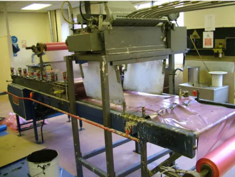
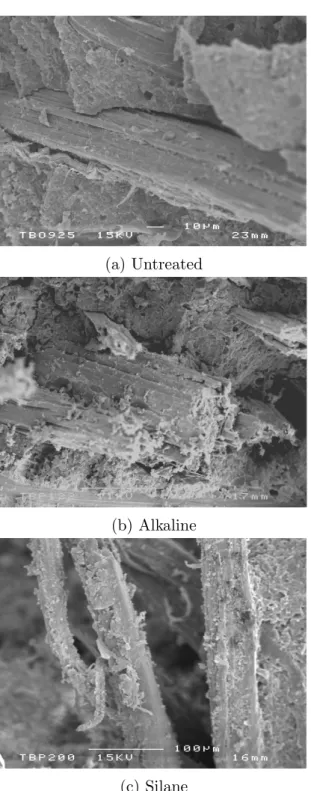
3.3 Photograph of the machine used to fabricate the SMC composites. 59 3.4 SEM micrographs of different surface treated hemp fibres. . . 63
LIST OF FIGURES
3.5 Tensile strength of (•) H-SMC composites and (◦) G-SMC com-posites as a function of fibre volume fraction. The dotted lines rep-resent the Kelly-Tyson model predictions for G-SMC and H-SMC and the solid line the modified Kelly-Tyson model predictions for H-SMC. . . 64 3.6 Schematic of cross section of a fibre bundle (technical fibre) in
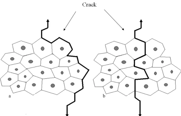
a matrix containing a crack. (a) The crack propagating through the fibre-matrix interface. (b) The crack propagating through the interfaces between the elementary fibres. Redrawn from Bos [2004]. 66 3.7 Tensile modulus of (•) H-SMC composites and (◦) G-SMC
com-posites as a function of fibre volume fraction. The dotted lines rep-resent the Cox-Krenchel model predictions for G-SMC and H-SMC and the solid line the modified Cox-Krenchel model predictions for H-SMC. . . 68 3.8 (◦) Tensile strength and (•) Young’s modulus as a function of
CaCO3 filler content of H-SMC composites. . . 69
3.9 SEM micrographs of tensile fracture surface of H-SMC compos-ites with different CaCO3 filler content at a constant fibre volume
fraction of 23 vol.%. . . 71 3.10 Tensile strength of (?) untreated, (•) alkaline treated, () silane
treated H-SMC composites as a function of surface treatment. (4) represents H-SMC composites based on hemp fibres treated with a fixed 2% alkaline treatment and varying concentration of silane treatment. . . 72 3.11 Tensile modulus of (?) untreated, (•) alkaline treated, () silane
treated H-SMC composites as a function of surface treatment. (4) represents H-SMC composites based on hemp fibres treated with a fixed 2% alkaline treatment and varying concentration of silane treatment. . . 73 3.12 SEM micrographs of tensile fracture surface of H-SMC composites
with different fibre surface treatments. . . 75 4.1 Specimens and loading configurations for pendulum tests. . . 82
LIST OF FIGURES
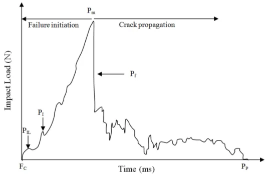
4.2 Example of load-time curves of an impacted composite material, adapted from Motuku et al. [2000]. . . 83 4.3 Schematic representation of the falling weight impact event. . . . 84 4.4 Typical force-deflection curves of H-SMC and G-SMC composites
with 26 vol.% fibre. . . 89 4.5 Penetration energy of (?) pure resin, (•) H-SMC and (◦) )
G-SMC composites as a function of panels thickness (t) fibre volume fraction (Vf) impactor diameter (Dt). The dotted lines represent the model predictions (equation 4.1) for G-SMC and H-SMC and the solid line represents the predications made using the modified model (equation 4.4) for H-SMC. . . 91 4.6 Absorbed energy vs. impact energy of H-SMC composites with
varying fibre volume fraction (?) 9 vol%, () 13 vol.%, (∗) 23 vol.%, (4) 37 vol.%, (•) 54 vol.% and (◦) 67 vol.% . . . 92 4.7 Effect of fibre volume fraction on H-SMC impact face damage. . . 93 4.8 (◦) Penetration energy and (•) absorbed energy as a function of
CaCO3 filler content of H-SMC composites . . . 94
4.9 SEM micrographs of impact fracture surface of H-SMC composites with different CaCO3 filler content. . . 95
4.10 Penetration energy of (?) untreated, (•) alkaline treated, (◦) silane treated H-SMC composites as a function of surface treatment. (4) represents H-SMC composites based on hemp fibres treated with a fixed 2% alkaline treatment and varying concentration of silane treatment. . . 96 4.11 Absorbed energy of (?) untreated, (•) alkaline treated, (◦) silane
treated H-SMC composites as a function of surface treatment. (4) represents H-SMC composites based on hemp fibres treated with a fixed 2% alkaline treatment and varying concentration of silane treatment. . . 97 4.12 SEM micrographs of impact fracture surface of H-SMC composites
LIST OF FIGURES
5.1 Typical force-time curves of H-SMC composite with a constant fibre content of 32 vol.% impacted at six incremental incident en-ergies: () 1 J, () 1.5 J, (•) 2 J, (◦) 2.5 J, (N) 3 J and (4) 3.5 J. . . 106 5.2 Typical force-deflection curves of H-SMC composite with a
con-stant fibre content of 32 vol.% impacted at six incremental incident energies: () 1 J, () 1.5 J, (•) 2 J, (◦) 2.5 J, (N) 3 J and (4) 3.5 J.107 5.3 Total absorbed energy as a function of incident impact energy of
H-SMC composites with varying different fibre volume fraction: () 9 vol.%, (◦) 20 vol.%, (N) 32 vol.% and () 46 vol.%. (∗) represents G-SMC composite with fibre volume fraction of 25 vol.%.109 5.4 Effect of impact energy on visual damage showing H-SMC
com-posite back (tensile) face damage. . . 111 5.5 Normalised residual flexural strength as a function of impact
en-ergy of H-SMC composites with varying fibre volume fraction: () 9 vol.%, (◦) 20 vol.%, (N) 32 vol.% and () 46 vol.%. (∗) represents G-SMC composite with fibre volume fraction of 25 vol.% . . . 112 5.6 Normalised residual flexural modulus as a function of impact
en-ergy of H-SMC composites with varying fibre volume fraction: () 9 vol.%, (◦) 20 vol.%, (N) 32 vol.% and () 46 vol.%. (∗) represents G-SMC composite with fibre volume fraction of 25 vol.% . . . 113 5.7 Absorbed energy as a function of incident impact energy of ()
untreated, (N) alkaline treated, (◦) silane treated H-SMC com-posites. () represents H-SMC composites based on hemp fibres treated with a fixed 2% alkaline-silane treatment. . . 115 5.8 Normalised residual flexural strength of () untreated, (N)
alka-line treated, (◦) silane treated H-SMC composites as a function of impact energies. () represents H-SMC composites based on hemp fibres treated with fixed 2% alkaline-silane treatment. . . . 117 5.9 Normalised residual flexural modulus of () untreated, (N)
alka-line treated, (◦) silane treated H-SMC composites as a function of impact energies. () represents H-SMC composites based on hemp fibres treated with fixed 2% alkaline-silane treatment. . . . 118
LIST OF FIGURES
6.1 Three loading modes: Mode I (tensile opening mode), Mode II (in-plane shear mode), and Mode III (anti-plane shear mode). . . 121 6.2 General loading on a body of thickness B and crack length,a. . . 122 6.3 The co-ordinate system used to describe the local stress around
the crack tip. . . 124 6.4 Examples of test configurations for fracture toughness testing of
composites. . . 127 6.5 Test specimen nominal dimensions (in mm) for compact tension
(CT) fracture toughness test. . . 129 6.6 Photograph of the initiator crack in an H-SMC composite specimen.130 6.7 Typical CT specimen load-displacement curves for H-SMC and
G-SMC composites at two distinct loading rates of 5 and 10 mm/min.132 6.8 Typical fracture patterns of H-SMC and G-SMC specimens. . . . 133 6.9 Fracture toughness, KIc, as a function of fibre volume fraction of
(•) H-SMC and (◦) G-SMC composites, together with the linear regression fitting for both composites. . . 134 6.10 Strain energy release rate,GIc, as a function of fibre volume
frac-tion of (•) H-SMC and (◦) G-SMC composites, together with the linear regression fitting for both composites. . . 136 6.11 (•) Fracture toughness, KIc, and (◦) strain energy release rate,
GIc, of H-SMC composites as a function of CaCO3 filler content
at a constant fibre loading of 20 vol.%. . . 138 6.12 Normalized fracture toughness, KIc, of H-SMC composites as a
function of different surface treatments. Alkaline-Silane (right col-umn) treatment represents H-SMC composites based on hemp fi-bres treated with a fixed 2% alkaline treatment and varying con-centration of silane treatment. . . 139 6.13 Normalized strain energy release rate, GIc , of H-SMC
compos-ites as a function of different surface treatments. Alkaline-Silane (right column) treatment represents H-SMC composites based on hemp fibres treated with a fixed 2% alkaline treatment and varying concentration of silane treatment. . . 140
LIST OF FIGURES
7.1 Life cycle of an automobile [Rebitzer et al., 2004]. . . 144 7.2 Framework for life cycle assessment [ISO14044, 2006]. . . 147 7.3 Life cycle inventories account for material use, energy, wastes,
emissions, and by-products over all of the stages of a product’s life cycle [Zhu, 2004]. . . 149 7.4 Process steps included in this study for the production of H-SMC
and G-SMC (reference material). . . 152 7.5 Graphical representation of the characterisation obtained by
scal-ing the effects due to various combinations of composite use (for non-automotive applications) and disposal. The sequence of bars in each category is the same as the sequence of codes, mentioned above the figure, starting from left top (GL) and ending at bottom right (HMI). . . 165 7.6 Graphical representation of the normalised effect score due to
var-ious combinations of composite use (for non-automotive applica-tions) and disposal. The sequence of bars in each category is the same as the sequence of codes, mentioned above the figure, starting from left top (GL) and ending at bottom right (HMI). . . 166 7.7 Graphical representation of the evaluated effect score due to
var-ious combinations of composite use (for non-automotive applica-tions) and disposal. The sequence of bars in each category is the same as the sequence of codes, mentioned above the figure, starting from left top (GL) and ending at bottom right (HMI). . . 167 7.8 Graphical representation of the indicator obtained by summarising
the evaluated numbers for non-automotive applications. . . 168 7.9 Graphical representation of the characterisation obtained by
scal-ing the effects due to various combinations of composite use (for automotive applications) and disposal. The sequence of bars in each category is the same as the sequence of codes, mentioned above the figure, starting from left top (GDL) and ending at bot-tom right (HMDI). . . 169
LIST OF FIGURES
7.10 Graphical representation of the normalised effect score due to var-ious combinations of composite use (for automotive applications) and disposal. The sequence of bars in each category is the same as the sequence of codes, mentioned above the figure, starting from left top (GDL) and ending at bottom right (HMDI). . . 170 7.11 Graphical representation of the evaluated effect score due to
var-ious combinations of composite use (for automotive applications) and disposal. The sequence of bars in each category is the same as the sequence of codes, mentioned above the figure, starting from left top (GDL) and ending at bottom right (HMDI). . . 171 7.12 Graphical representation of the indicator obtained by summarising
the evaluated numbers for automotive applications. . . 172 8.1 The cross-sectional view of flax fibre showing around 7 fibre cells
to-gether forming a technical flax fibre (fibre bundle)(Source: [Garkhail,
List of Tables
2.1 Dimensions of selected natural fibres. Data from [Lilholt & Lawther,
2000]. . . 22 2.2 Chemical composition and structural parameters of selected
natu-ral fibres [Mohanty et al., 2000] . . . 23 2.3 Mechanical properties of natural fibres compared to conventional
fibres [Li et al.,2005] . . . 29 2.4 Physical characteristics of plant fibres [Garkhail,2001] . . . 29 3.1 Recent studies where alkaline and silane surface treatments have
been used to enhance the mechanical performance of natural fibre reinforced composites. . . 54 3.2 Specific properties and price/performance index of G-SMC and
H-SMC composites at three different fibre volume fractions. . . . 67 3.3 Specific properties and price/performance index of G-SMC and
H-SMC composites at different CaCO3 filler content. . . 70
4.1 Charpy and Izod are the two most common methods used to test the impact response of various forms of natural fibre composites. . 81 7.1 Required properties for an automotive application [Vissers, 2000]. 153 7.2 The estimated (approximate) fibre volume fraction (Vf) and weight
fraction (Wf) of H-SMC and G-SMC required to obtain the re-quired property for an automotive application. . . 154 7.3 . . . 154
LIST OF TABLES
7.4 Calculation of additional fuel consumption because of added weight, for strength criterion . . . 157 7.5 Calculation of additional fuel consumption because of added weight,
for stiffness criterion . . . 158 7.6 The criteria used for selecting the most suitable impact assessment
methods (http://www.pre.nl). . . 159 7.7 Results of Simapro method selector (http://www.pre.nl) . . . 160 7.8 Eco-indicator 99 normalization and weighting values for egalitarian
perspective. . . 161 7.9 The different characteristics of the three different perspectives in
Eco-indictor 99 method. . . 162 7.10 Codes used for various combinations of composite criterion, use
Chapter 1
Introduction
Generally speaking, a composite is considered to be any multiphase material that exhibits a significant proportion of the properties of both constituent phases such that a better combination of properties is realised [Callister, 2003]. In ad-dition, the constituent phases must be chemically dissimilar and separated by a distinct interface. Many composite materials are composed of just two phases; one is termed the matrix, which is continuous and surrounds the other phase, often called the dispersed phase or reinforcement. Figure 1.1 shows a simple classification scheme of composite materials. In engineering, the most important composites are those in which the dispersed phase is in the form of a fibre or filler. Fillers are usually added to the matrix phase to improve both the mechan-ical properties and reduce the overall cost of the composite. In fibre-reinforced composites the fibres have very high strength and modulus with small diameter in the range 7-15µm [Hull & Clyne,1981] while the matrix is ductile or brittle with usually considerable resistance to chemical environments. By combining fibre and matrix a composite material is produced with high strength and stiffness that is also considerably chemical resistant. The matrix phase of fibre composites may be a metal, polymer or ceramic. Polymers are most widely used as matrix ma-terials because of their ductile and low density properties. There are two main types of polymers with both thermosets and thermoplastics used as matrix in composite materials. Figure 1.2 shows the most commonly used thermoplastic and thermosetting resins.
Figure 1.1: Characterisation of composite materials.
1.1 Thermosetting composites
In thermosets, the liquid resin is converted into a hard brittle solid by a cross-linking process which leads to the formation of a tightly bound three-dimensional network of polymer chains. The mechanical properties depend on the molecular units making up the network and on the length and density of the cross-links. Epoxy and polyester resins are the most commonly used thermosetting polymer resins in the composite industry due to the range of physical and mechanical properties that they impart.
In thermoplastic, the liquid resin can be repeatedly softened by heating and hardened by cooling. Unlike thermosets, the molecular chains in thermoplastic resins do not form cross-links. The most commonly used contemporary thermo-plastic resins are polyethylene and polypropylene.
The composite material developed in this study is based on thermosetting resin and therefore the literature onwards will mainly be focused on thermosetting resins and more specifically on polyester resin.
1.1
Thermosetting composites
Thermosetting resins have been used in composites as early as 1909 in the form of phenolics. However, it was not until the 1940s that growth of the structural composite industry saw thermosetting resin used in significant quantities [ Holl-away,1994]. As matrix materials for composites, thermosetting resins offer a wide range of advantages over thermoplastics, including low viscosity, higher strength, better wetting and impregnation of the fibres, lower temperature and low pres-sure for processing, and hence less expensive product tooling. In the current research an unsaturated polyester resin is used to improve the cost-performance of the thermosetting composite. Polyester resins offer a number of advantages for high volume composites applications such as low price and good wear properties. Moreover, polyester resins have good chemical and water resistance and can be easily processed.
Polyester is formed from a reaction between a dicarboxylic acid and a dialco-hol. The polymer is linked by ester functional groups and the resulting polymer is called polyester. The chemical reaction to form polyester is shown in Figure 1.3.
1.1 Thermosetting composites
Figure 1.3: Schematic of the chemical reaction to form polyester.
Polyester is a thermosetting resin that contains two or more double bonds between the carbon atoms and is therefore referred to as unsaturated. There are two principal types of polyester resins used as standard laminating systems in the composites industry. Orthophthalic polyester resin is the standard economic resin used for many applications. Isophthalic polyester resin is now becoming the preferred material in industries such as marine where its superior water resistance is desirable.
Polyester thermosetting resins are produced by polymerising a linear polyester resin with a low molecular weight co-reactant. The most popular co-reactant is styrene because it is low cost, copolymerises readily with polyester aliphatic unsaturated groups and makes the resin easier to handle by reducing its viscosity. The styrene content of polyester resins ranges from 15 to 50 wt.%. A molar ratio of at least 2, of styrene unsaturated groups over polyester unsaturated groups, is usually required to achieve decent curing kinetics. Catalysts are added to the resin system shortly before use to initiate the polymerisation reaction. The catalyst does not take part in the chemical reaction but simply activates the process. An
1.1 Thermosetting composites
accelerator is added to the catalysed resin to enable the reaction to proceed at workshop temperature and/or at a greater rate.
The molecular chains of the polyester can be represented as shown in Figure 1.4, where ’R’ indicates the reactive sites in the molecule. With the addition of styrene, and in the presence of a catalyst, the styrene cross-links the polymer chains at each of the reactive sites to form a highly complex three-dimensional network.
Figure 1.4: Schematic showing the polymerising of a linear polyester resin to form a complex three-dimensional structure of a thermoset polyester resin.
The polyester resin is then said to be ‘cured’ and is now a hard solid. The cross-linking or curing process is called ‘polymerisation’. It is a non-reversible re-action. Polyester resins are used in a variety of processing methods, including
in-1.2 Processing of thermosetting composites
jection moulding, pultrusion, filament winding, compression moulding, and resin transfer moulding. Many polyester formulations contain thickening agents that make them suitable for sheet moulding compounds (SMC) or bulk moulding com-pounds (BMC). Polyester composite products range from furniture, playground equipment, bowling balls to boats, automotive body panels, and chemical storage tanks. Polyester resins when unmodified are transparent, are also commonly used as coating materials, for example, as gel coats on boat hulls, combining the good mechanical and chemical resistance of these materials.
1.2
Processing of thermosetting composites
One of the principal processing methods for the production of short glass fibre reinforced thermosetting composites is sheet moulding compound (SMC). In a SMC process the fibre reinforced composite is produced in sheet form. SMCs are one of the most widely used type of thermoset composites due to their good mechanical and aesthetical properties. They are used in many applications in the production of industrial components, for a variety of different sectors ranging from sport to automotive and marine fields, just to mention a few (Figure 1.5).
Figure 1.5: Rear boot of a car made of sheet moulding compounds with carbon fibre as the reinforcing agent.
1.2 Processing of thermosetting composites
SMC composites are usually made with glass fibres, chopped into small seg-ments and distributed in random orientation in a resin system. The resin system is made by mixing other ingredients with polyester resin, such as:
(i) catalyst (ii) filler
(iii) release agent (iv) stretching agent (v) thickening agent
(vi) thermoplastic additives and (vii) pigment
The function of the catalyst is to reduce the reaction activation energy between the unsaturated resin chains and the styrene which acts as a bridge between the resin chains in order to give the required reticulation. The choice of the catalyst depends on the polymerisation temperature of the compound, which normally varies between 140 and 160◦C. The catalyst makes up only 0.3-1.5% of the resin system. The most commonly used catalysts are peroxides due to their low cost. However, these catalysts are unstable and therefore are controlled through the addition of inhitors such as benzoquinone. The filler is used to reduce the cost of the product, decrease shrinkage of the resin, and improve the surface finish. Furthermore, fillers enhance the dimensional stability of the product; also improve the wettability of the material and its filling capacity inside the mould. The most commonly used filler in SMC composites is calcium carbonate CaCO3. The
function of the release agent is to create a resin incompatible oily film thereby enabling detachment of the piece from the mould. Normally Ca and Zn stearate are used as release agents making up 1-2% of the resin system. Stretching agents such as polyurethane are used to increase the elastic modulus of the component and to provide shock resistance. They are also used to fill the mould better as they have low-shrinkage. The function of the thickening agent is to increase the
1.2 Processing of thermosetting composites
viscosity of the resin system therefore making it easier to reproduce the resin system with the same properties. The thickening agent makes up 1-3% of the resin system. The most widely used agent is magnesium hydroxide (MgOH2) due
to its low cost. Ionic links are formed between magnesium and the carboxylate group (-COOH) on the resin chains, which causes the viscosity to increase. The role of thermoplastic additives is to reduce the shrinkage of the SMC material. They act by inserting themselves between two polymer chains and forcing the styrene to be attached in the most expanded possible way. For this purpose vinyl acetate and polystyrene are used as thickening agents. Pigments are added to the SMC to impart colour to the component. They are usually added in powder form in quantities ranging from 1-5%. Figure 1.6 shows a diagrammatic picture of a SMC manufacturing machine.
Figure 1.6: The production process for SMC sheets.
The process of manufacturing glass fibre reinforced SMC begins when contin-uous strands of glass fibre (roving) are chopped into required lengths (usually less than 50 mm). The chopped strands are deposited onto a bottom layer of paste made from resin and filler. The paste and chopped glass fibre strands travel
1.2 Processing of thermosetting composites
through the processing machine, on a carrier film. A top layer of resin and filler paste sandwiches the fibres to the bottom layer of paste, and is covered by a top layer of carrier film. The “fibre and paste sandwich” is then compacted by a series of rollers to make a continuous sheet of moulding compound. Figure 1.7 shows examples of sheets of moulding compound.
Figure 1.7: Picture of glass fibre SMC prepregs.
The sheets are then stored for a few days before moulding to allow the prepreg to thicken to a mouldable viscosity. The aged SMC is then weighed, and placed into a heated compression mould (120-180◦C) which under pressure (500-2500 bar) forms a composite part (Figure 1.8). Typical compression moulding cycle times of 30 seconds to several minutes are possible with thicker parts requiring more dwell/curing time.
1.3 Thermosetting composite reinforcements
Figure 1.8: Schematic of SMC prepreg loading into a compression press.
1.3
Thermosetting composite reinforcements
Glass fibres are by far the most extensively used reinforcements in thermosetting composites because of their excellent cost-performance ratio. However, glass fi-bres have some disadvantages; like problems associated with the disposal of glass fibre filled composites at the end of the materials lifetime since they cannot be thermally incinerated/recycled and they leave behind a residue that can damage the incineration furnace. Additionally these fibres are very abrasive which leads to increased tool wear therefore increasing overall maintenance cost. Furthermore, glass fibres pose some health and safety problems, like skin irritations during han-dling of the products and glass fibres are (although still not scientifically proven) suspected to affect the lungs both during production and use.
In recent years the interest in natural materials has increased considerably due to the increased awareness of environmental and recyclability issues. Envi-ronmental legislation as well as ethical consumerism is putting pressure on man-ufacturers of material and end-products to consider the environmental impact of
1.3 Thermosetting composite reinforcements
their products at all stages of their life-cycle.
In light of all these environmental concerns, composite manufacturers are turn-ing their attention to more environmental friendly reinforcements such as plant fibres like flax, hemp, jute, kenaf and sisal. There are many research papers avail-able reviewing the properties, performance and applications of natural fibres and their composites [Hassan et al.,2010;John & Thomas,2008;Mantia & Morreale,
2011; Mukherjee & Kao,2011; Summerscaleset al., 2010a,b; Thiruchitrambalam
et al., 2010; Zini & Scandola, 2011].
Plant fibres have some advantages which make them suitable for reinforcement in composites materials:
• They are a renewable and abundant resource [Wu, 2009], while the amount of energy necessary for its “production” is lower than that of glass,
• They can be incinerated for energy recovery since they possess a good calorific value with no residue left in the combustion furnaces [Georgeet al.,
2001],
• The amount of CO2 uptake during its growth and the efforts necessary to
grow and harvest the fibre is matched with the CO2which is released during
the rotting or burning process. Natural fibres are therefore favoured for the overall CO2 balance,
• The result in less abrasive wear of processing equipment: Natural fibres do less mechanical damage to processing equipment and tooling during process-ing (e.g. mould shear edges), recyclprocess-ing (e.g. extruders), etc, thus lowerprocess-ing overall maintenance costs compared to glass [de Bruijn, 2000],
• They possess a low specific weight which results in a higher specific stiffness and possibly strength than glass fibre [Peijs,2000; Singleton et al., 2003], • They can be produced with low investment cost, particular for non-wovens
[Joseph et al., 2000],
• Due to their natural origin, natural fibres do not cause skin irritation during handling and when these fibres are applied in thermoplastic products, no sharp fibres or sharp splintering occurs during collision,
1.4 Natural fibre composites: an introduction
• They possess good thermal and acoustic insulating properties
• They are biodegradable leading to fully biodegradable composites when added to a biodegradable resin
• Natural fibres generally have a significantly lower density (about 40% less) compared to glass, which gives better fuel efficiency (or maximum load ca-pacity) when their parts are applied in transportation applications [de Bruijn,
2000].
Natural fibres are abundantly available in developing countries like Bangladesh and India, therefore it is in the economic interests of these countries to research new applications areas like composite reinforcement. Another positive outcome of using natural fibres is that workers in developing countries will benefit directly from the economical possibilities of natural fibre composite. With the upgrading of indigenous technology, enterprising workers will both increase their ability to generate income and will finally receive the recognition they lack in developing countries [Rijswijk et al., 2003].
1.4
Natural fibre composites: an introduction
The concept of using natural fibres as reinforcement in composite materials is not a new idea. Man has been using natural fibres, as construction materials for buildings for centuries. The first composite materials known in history were reinforced with natural fibres. In ancient Egypt some 3,000 years ago; bricks were made from a mixture of straw and loam, dried in the sun. Additionally the first polymer matrix composites developed in the early 20th century were reinforced with natural fibres. Large quantities of sheet, tubes and pipes for electronic purposes were reinforced with paper or cotton. In the 1950s for example, the body of the East German car ’Trabant’ was made of natural fibres (cotton) embedded in a polyester matrix. However with the advent of metals and the steadily rising performance of technical and standard plastics and the development of synthetic fibres with better performance, the use of natural fibres for reinforcing purposes declined. Since then, the use of natural fibres was limited to the production
1.5 Natural fibre composites: present & future applications
of rope, string, clothing, carpets and other decorative products. The rise of composite materials began during the 1960s when glass fibres in combination with tough rigid resins could be produced on a large scale.
In recent years much of the research has been focused on natural-fibre-reinforced composites based on either thermosetting matrices like polyester and epoxy [Aziz
et al., 2005; Dhakal et al., 2007b; George et al., 1999; Hepworth et al., 2000;
Satyanarayana et al., 1986; Towo & Ansell, 2008] or thermoplastics matrices, such as polypropylene (PP) or polyethylene (PE), together with various types of plant and crop fibres [Adedelmoulehet al., 2007; Bledzkiet al., 2004; Bos et al.,
2006; Facca et al., 2007; Garkhail et al., 2000; Georgopoulos et al., 2006; Liu & Dai, 2008; Panthapulakkal & Sain, 2007; Zampaloni et al., 2007]. The principal advantage of polyester resin as matrix material for natural fibre composites is their low cost. Moreover, polyester resins offer a balance of properties (including mechanical, chemical and electrical) dimensional stability. Also, polyester resins offer other advantages like ease of handling and processing.
1.5
Natural fibre composites: present & future
applications
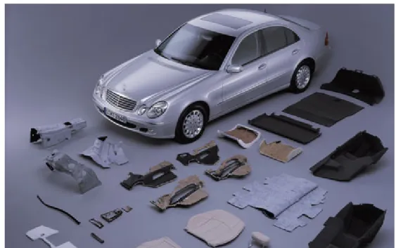
Presently, natural fibres are used as reinforcements for technical applications in the automobile and packaging industries (e.g. egg boxes). Flax and hemp are the two most common fibres used in the automobile industry for door panels, seat backs, headliners, package trays, dashboards, and trunk/boot liners. Most of the developmental work for natural fibre composites in interior trim was focused on polypropylene (PP) based composites produced by compression moulding, thermoforming extruded sheet or commingled mats of PP and plant fibres. Figure 1.9 shows sections of a Mercedes car made of flax fibre reinforced thermoplastic resin.
1.5 Natural fibre composites: present & future applications
Figure 1.9: Various car components that are made of flax fibre reinforced polypropylene for a Mercedes car (Photo courtesy of Daimler Chrysler AG).
Natural fibres are also used to produce door upholstery and furniture (Figure 1.10). Another large-scale application of natural fibre is to use them as building materials. An important advantage of thermosets over thermoplastics in building applications is that they offer better wetting of the fibres due to lower viscosity and hence superior mechanical properties. Composites are emerging with an increasing role in building materials to replace timber, steel, aluminium, concrete etc. In contrary to India where natural fibre reinforced materials have been used for building and similar applications for many years, application in the western world started in the mid-nineties in Japan and in the US followed more recently by Europe. With the scarcity of natural wood, the application of wood and plant fibre filled materials is set to increase. The market for wood plastic composites (WPC) has recorded growth rates of 100% between 1995 and 2000 in the USA [Bledzki et al., 2002].
1.5 Natural fibre composites: present & future applications
1.6 Natural fibre composites: barriers & challenges
The applications of natural fibres are also increasing and products that were once made of natural wood, metals and glass fibre reinforced composites are being replaced by natural fibre materials. The next step for natural fibres is to be used for advanced composite applications such as aerospace and as load bearing structures. There has to be much research carried out on fibre properties, interface properties and fibre quality to develop such advanced composites based on natural reinforcements. However, due to advantages of weight, mechanical stability and price, interest in the application of natural fibre composites is growing in the aerospace industry in both the US and Europe [Bledzki et al., 2002].
Pandeyet al.[2010] have analysed the recent advancement in the application of cellulose based materials in different sectors including: building and construc-tion industry, adhesives and cellulose-based nanocomposites and have given a future perspective of natural fibres and their composites.
1.6
Natural fibre composites: barriers &
chal-lenges
For a successful application of natural-fibre-reinforced thermosetting composites in engineering applications some barriers have to be overcome:
1. Natural fibres are hydrophilic where most polymeric resins are generally hydrophobic, meaning there is poor interaction between the fibre and matrix leading to a weak interface, resulting in inferior mechanical performance [Wambua et al., 2003a] and increased water absorption [Arbelaiz et al.,
2005a].
2. Natural fibres have a high rate of moisture absorption that can affect the durability of the composite in outdoor applications as well as its suscepti-bility to poor dimensional stasuscepti-bility and rotting [Peijs et al., 1998]. Microc-racking of the composite resulting from fibre swelling [Hill & Hughes,2010] can result in degradation of mechanical properties.
3. Natural fibre composites tend to have low impact strength. The reason for this is not yet all that well understood but it maybe due to either the poor
1.7 Research partners
fibre-matrix adhesion resulting in extensive fibre pull-out without much energy being absorbed or a too strong interface leading to brittle fracture without any fibre pull-out.
4. The processing temperature of composites has to be relatively low in order to not degrade the natural fibres
5. The quality of the fibres is variable because it depends on unpredictable in-fluences such weather and soil content. Also the use of fertilisers, herbicides and other chemicals to grow the plant can have hazardous impact on the bio-sphere. This tends to off-set the advantages gained at end-of-use such as CO2 neutral and incineration for energy recovery.
6. The growing of these fibres would occupy land which could be used to grow food.
1.7
Research partners
The work described in this thesis has been performed at QMUL (Queen Mary University of London) from roughly 2004 to 2008. This work has been performed in conjunction with:
• Funding by Technology Strategy Board (TSB): the Engineering and Phys-ical Sciences Research Council (EPSRC),
• The Building Research Establishment (BRE): which is a world leading re-search, consultancy, training, testing and certification organisation,
• Menzolit Ltd : one of the largest producers of SMC and DMC composites in the world
• Hemptechnology Ltd: non-woven hemp mats were purchased from Hemptech-nology Ltd.
Hemp fibre was selected for the study because of its availability in the UK. This study was initiated because of the sustainable nature of hemp fibres along with the economical benefits foreseen from hemp fibres.
1.8 Aims & Objectives
1.8
Aims & Objectives
The overall objective of the present project was to examine the possibility of re-placing E-glass fibres with natural fibres as reinforcement in sheet moulding com-pounds (SMC). The main application area for these composites was for building materials such as false walls and ceiling panels.
The specific aims of the study were:
1. To optimise the mechanical performance of the H-SMC composites in terms of fibre volume fraction and CO2 filler content.
2. To enhance the mechanical properties of these H-SMC composites by modi-fying the fibre-matrix interface via chemical modifications with alkaline and silane treatments.
3. To compare the experimentally obtained tensile strength and modulus of H-SMC composites with theoretical predictions made using micromechanical models of tensile strength and modulus.
4. To study the influence of impact damage on the residual flexural strength of these H-SMC composites.
5. To develop a simple mechanical model to better understand the impact behaviour of the H-SMC composites.
6. To investigate the fracture toughness properties of these H-SMC composites in terms of the critical-stress-intensity factor KIc and critical strain energy release rate GIc.
7. To compare the environmental impact of H-SMC composites with conven-tional glass fibre reinforced (G-SMC) composites.
1.9
Structure of this thesis
In keeping with the layout of a traditional thesis the present report is organised into sub-sections in the following way:
1.9 Structure of this thesis
Chapter 2: A literature review on natural fibres in general and hemp fibres is reported. A brief history on natural fibres and their physical and chemical structures are given. Additionally details of how hemp fibres are extracted from the hemp plant is presented as well as the mechanical properties of various natural fibres in comparison with traditional fibres.
Chapter 3: This chapter involves chopped random hemp fibre mat rein-forced composites. The results on the optimisation of the mechanical properties of hemp/polyester composites manufactured through a sheet moulding process (SMC) followed by compression moulding of these hemp fibre mats impregnated with thermoset unsaturated polyester resin are reported and discussed. The ef-fects of hemp fibre content, CaCO3filler content and fibre-matrix interfacial
adhe-sion on the macromechanical properties of composites are reported and discussed. To provide a better understanding of the mechanical behaviour of the compos-ites the experimental results are compared to theoretically calculated mechanical results generated from modified micromechanical models for random fibre com-posites, which take into account the effect of composite porosity on the composite properties.
Chapter 4: As discussed above, natural fibre reinforced composites have often poor properties in impact. In this chapter the impact behaviour of hemp fibre composites are tested using the falling weight impact method and are presented and discussed. Again the effect of hemp fibre content, CaCO3 filler content and
fibre-matrix interfacial adhesion on the penetration and absorbed energies of the composites are reported and discussed. A simple mechanistic model has been developed for this hemp fibre composite and is used to get a better insight into the impact behaviour of these composites as well as to provide a guideline to compare the experimental results with theoretically calculated data.
Chapter 5: In this chapter the residual flexural properties after low velocity non-penetrating impact of hemp fibre composite are compared to glass fibre com-posites and presented here. The effect of incident impact energy and fibre volume fraction on the damage tolerance and residual properties of H-SMC is discussed. Chapter 6: The fracture toughness properties in terms of the critical-stress-intensity factor KIc, and critical strain energy release rate, GIc, of H-SMC are studied using compact tension (CT) method and presented in this chapter. The
1.9 Structure of this thesis
influence of hemp fibre content and CaCO3 filler content on the fracture
tough-ness rate is reported. Also the influence of fibre surface treatments on fracture toughness is studied and discussed.
Chapter 7: Here a study is presented on the environmental impact of the various types of hemp fibre reinforced materials using a life cycle assessment (LCA) technique.
Chapter 8: Finally, some general conclusions and recommendation for future work are given.
Chapter 2
Natural fibres
The cell is one of the most basic units of life. All living organisms from plants to animals are built up of cells. However, there is one factor that distinguishes plant cells from animal cells. Plant cells have a rigid cell wall whereas animal cells do not. The plant cell walls are usually enlarged and this makes these cells responsible for the good structural integrity of the plants. The cell walls are elongated in shape with a high aspect ratio (length/diameter ratio) and hence they are often called fibres. A single cell of the plant is often termed elementary fibre. The fact that natural fibres come from natural origin means that the dimensions of each fibre is different even if the fibres are from the same plant. The dimensions of some of the most commonly used natural fibres as reinforcement in composite materials are given in Table 2.1. The major part of this research has been done on hemp fibres. However, where results and theories were not available for hemp, information based on other bast and wood fibres has been presented. It is assumed that the observations made on these fibres can be applied to ligno-cellulose fibres from other plants as well.
2.1
Classification of natural fibres
Natural fibres can be derived from either plant or animal sources. The majority of useful natural textile fibres are plant based with the notable exceptions of wool and silk.The classification according to natural and plant origin is shown in
2.2 Natural fibre composition
Table 2.1: Dimensions of selected natural fibres. Data from [Lilholt & Lawther,
2000].
Fibre type Elementary fibre length, mm Elementary fibre width,µm
Flax 33 (9-70) 19 (5-37) Hemp 25 (5-55) 25 (10-50) Jute 2 (2-5) 20 (10-25) Sisal 3 (1-8) 20 (8-41) Cotton 18 (10-40) 20 (12-38) Softwood 3.3 33 Hardwood 1.0 20
Figure 2.1 which is based on the most commonly used fibres. There are at least 1000 types of plants that bear fibres which can be used as reinforcement in com-posite materials. The plant-based fibres are extracted from different parts of the plant such as stems, leaves and seed hairs. The most widely used plant fibres as composite reinforcement are the bast fibres including flax, hemp, kenaf, sisal and jute. These fibres are abundantly available throughout the world, particularly in developing countries like China, India and Brazil and they come from renewable resources. Other large sources of natural fibres are recycled waste paper and wood, also agricultural residues such as rice and coffee husks, bagasse, and many more.
2.2
Natural fibre composition
Although there are considerable differences in the physical features of the various vegetable fibres, there is also a great similarity among all these fibres. In general, natural fibres are composed principally of four chemical groups: cellulose, hemi-cellulose, lignin, and a miscellaneous group which includes pectinaceous materials, inorganic compounds, etc. It is these components that determine the mechanical properties of the fibre and therefore of the plant. The molecular structure and composition of these polymers is very different. Furthermore the content of these polymers is highly variable between plants fibres and is influenced by climatic conditions, age and the digestion process (Table 2.2).
2.2 Natural fibre composition
Figure 2.1: Classifications of fibre according to origin.
Table 2.2: Chemical composition and structural parameters of selected natural fibres [Mohanty et al., 2000]
Fibre Cellulose Lignin Hemicellulose Pectin Wax Microfibril
wt.% wt.% wt.% wt.% wt.% angle (◦) Hemp 70.2-74.4 3.7-5.7 17.9-22.4 0.9 0.8 6.2 Flax 71 2.2 18.6-20.6 2.3 1.7 10.0 Jute 61-71.5 12-13 13.6-20.4 0.2 0.5 0.8 Sisal 67-78 8-11 10.0-14.2 10.0 2.0 20.0 Cotton 82.7 - 5.7 - 0.6 -Softwood 40-44 25-31 25-29 - - -Hardwood 43-47 16-24 25-35 - -
-2.2 Natural fibre composition
Cellulose, the major constituent is a long-chain polymeric poly-saccharide car-bohydrate, of beta glucose. The cellulose monomers are linked together through beta-1,4 glycosidic carbon bonds by condensation (Figure 2.2). The repeating unit in a cellulose chain consists of two glucose units, which are orientated 180◦ to each other. Cellulose is a flat and ribbon-like linear chain polymer. The degree of polymerisation (DP) is the number of glucose units in the chain. On average DP of wood is 10,000 [Siau, 1995], for hemp fibre it is 7000 [Thygesen et al.,
2002]. Cellulose fibres usually consist of over 500,000 cellulose molecules with 2.5 billion hydrogen bonds. It is the large number of hydrogen bonds, which is the basis of high tensile strength of cellulose, with a theoretical strength of about 15 GPa in the chain direction [Lilholt & Lawther, 2000].
Figure 2.2: Structured formula of cellulose [Lu et al., 1999].
Cellulose is synthesised in the cell wall of the plant. The glucose monomers in cellulose form hydrogen bonds within its own chain producing an elementary fibrillar unit, called amicellar strand. When hydrogen bonds are formed between chains they produce a large microfibril. The number of cellulose chains in a mi-crofibril varies depending on the type of plant. The cellulose chain is divided into two distinct regions: regions of high order, i.e. crystalline region, and regions of low order, i.e. amorphous regions. It is generally agreed that these regions are not well defined but, rather, the transition is gradual from crystalline to amor-phous, i.e., there are various degrees of lateral order. The degree of crystallinity varies depending on the fibre; for wood fibres it between 60 and 70% [Siau,1995] and for cotton fibres it is between 40 and 45%. With a few exceptions, natural
2.2 Natural fibre composition
cellulosic fibres have a cellulose I crystal lattice structure.
Hemicellulose is a polysaccharide composed of a variety of carbohydrates in-cluding glucose, xylose, arabinose, galactose and mannose (Figure 2.3). Com-pared to cellulose, hemicellulose molecules are more branched, non-linear and have lower molecular mass with a degree of polymerisation (DP) between 50 and 200. The most prevalent hemicellulose polymer chains are xylans and glucoman-nans. Hemicellulose forms covalent bonds to lignin by attaching ferulic acid and p-coumaric residues [Bjerre et al., 1997]. Hydrogen bonds are formed between xylan and cellulose. The degradation of the bonds in hemicellulose leads to the disintegration of the fibres into cellulose microfibrils resulting in lower fibre bundle strength.
Figure 2.3: Structural formula of hemicellulose (courtesy Sigma-Aldrich).
Lignin is a complex polymer of phenylpropane units, which are cross-linked to each other with a variety of different chemical bonds (Figure 2.4). Lignin is a highly branched molecule which consists of various types of substructures which repeat in random manner. The mechanical property of lignin is about 4 GPa (Young’s modulus), much lower than that of cellulose [Bledzki & Gassan, 1999].
2.2 Natural fibre composition
2.3 Structure of a single natural fibre
2.3
Structure of a single natural fibre
The wall of a plant cell is composed of three major layers: the middle lamella, a primary wall and a second wall (Figure 2.5). The middle lamella, composed mainly of lignin and pectin, serves as the glue bonding adjacent cells together. The wall itself is made up of a primary wall and a three-layered secondary wall. The cellulose microfibrils in the primary and secondary walls are aligned in a certain way, and it is the angle that the microfibrils are to the axis of the cell wall that is defined as the microfibril angle. The microfibril angle generally de-termines the mechanical properties of cellulose based fibres. Table 2.2 gives the microfibril angle of some common natural fibres and wood. In the primary wall the microfibrils form a loose, irregular net-like orientation. The outer layer of the secondary wall is called the transition layer because its structure is intermediate between the structure of the primary wall and the secondary wall. In the outer layer, the microfibrils are more precisely oriented, but are nearly perpendicular to the long axis of the cell at an angle of about 50◦ to the fibre axis. In the middle layer of the secondary wall, the microfibrils run almost parallel to each other in a tight helix structure around the cell, forming an angle of 10 to 20◦. This layer is the thickest, forming between 60 to 80% of the cell wall [Siau,1995] and therefore the microfibril angle in this layer has the greatest effect on the overall properties of the fibre. The smaller the angle the microfibrils make with the long direction of the cell, the stronger the cell is. It is stated that lower microfibril angles in the middle layer results in fibre bundles with high tensile strength, about 1200-1500 MPa for hemp fibre [Garkhail, 2001]. In the inner layer of the cell wall, the microfibrils are once again oriented almost at right angles to the cell’s long axis. Several studies of fibre composition and morphology have found that the microfibril angle tends to control the mechanical properties of cellulosic fibres. It was reported that a lower microfibril angle resulted in higher work of fracture in impact testing [Pavithran et al., 1987].
2.4 Physical & mechanical properties
Figure 2.5: Cross-section of a hemp fibre (Courtesy of DoITPoMS Teaching and Learning Packages, University of Cambridge).
2.4
Physical & mechanical properties
The mechanical and physical properties of different natural fibres are given in Table 2.3 and 2.4. The specific strength and stiffness of natural fibres are com-parable to those of E-glass fibres. However, due to their natural origin they show much higher variability of the various parameters than synthetic fibres [Virket al.,
2010]. The properties of the natural fibres are influenced by several factors such as:
2.4 Physical & mechanical properties
Table 2.3: Mechanical properties of natural fibres compared to conventional fibres [Li et al., 2005]
Fibre Density Elongation Tensile Young’s
(g/cm3) (%) strength (MPa) modulus (GPa)
Hemp - 1.6 690 -Flax 1.5 2.7-3.2 345-1035 40-70 Jute 1.3 1.5-1.8 393-773 26.5 Sisal 1.5 2.0-2.5 511-635 9.4-22.0 Cotton 1.5-1.6 7.0-8.0 287-597 5.5-12.6 Softwood Kraft 1.5 - 1000 40.0 E-glass 2.5 2.5 2000-3500 70.0 Carbon (standard) 1.4 1.4-1.8 3000 230
Table 2.4: Physical characteristics of plant fibres [Garkhail, 2001]
Fibre
Specific
Moisture
Absorption
Volume
gravity (g/cm
3)
regain (%)
(%)
swelling (%)
Cotton
1.52
7-8.5
7-8
-Flax
1.40
12
7
30
Jute
1.46
14
12
45
Hemp
1.48
12
8
-Sisal
1.20-1.45
-
11
40
• All natural fibres containdefects and imperfections, which reduce the strength. The extent of these cracks is dependent on the anisotropy of the fibre struc-ture, and for high anisotropy the stress concentration of transverse cracks is low and thus not a decisive factor for fibre strength. The origin of defects in natural fibres and how, ultimately, they affect the properties of composite materials reinforced with such fibres has been reviewed by [Hughes, 2012].
2.4 Physical & mechanical properties
• Fibre length: the strength of all fibres is dependent on the test length. How-ever, the strength of natural fibres is significantly more dependent on the length of the fibre than for the case of glass fibres [Mieck et al., 2003] be-cause strength at fibre lengths exceeding the cell length is controlled by the bonding between cells rather than the intrinsic strength of the elementary cells or fibres.
• The fibre diameter and cross-sectional shape also influences the tensile strength [Mukherjee & Satyanarayana, 1986] and modulus [Summerscales
et al., 2011] of the fibre, with smaller diameter fibres having higher tensile strength and modulus.
• The degree of cellulose crystallinity. Natural fibres consist of regions which are less ordered i.e. amorphous regions which are potential weak points due to the lower number of chains per cross-sectional area resulting in low local strength.
• The tilt angle of the cellulose microfibrils to the longitudinal axis of the fibre, i.e the microfibril angle greatly influences the tensile strength and stiffness of the fibre. High fibre strength is obtained by a lower microfibril angle i.e. about ±5◦, the microfibril angle for hemp is one of the lowest at 6.2◦ and for flax it is 10◦ [Bledzki & Gassan, 1999]. The microfibril angle for wood fibres varies greatly from 5◦ to 60◦ .
• The degree of polymerisation of the highly orientated cellulose microfibres affects the strength of the fibre, in general the strength is inversely propor-tional to the degree of polymerization for fibres with ideal structure. • The cellulose content of the fibres also influences the fibre strength, fibres
having higher cellulose content results in high tensile strength. The cellulose content and the microfibril angle are presented in Table 2.2, it can be seen that the cellulose content of hemp and flax fibres is 78% and 71% by weight respectively.
Many of these factors work together to reduce the strength of the fibre, e.g., high orientation leads to anisotropy, which reduces the severeness of cracks and
2.4 Physical & mechanical properties
the amorphous region, effecting the degree of polymerisation. Moreover, proper-ties depend on growing (climate), harvesting conditions and processing methods. This poses two problems: quality characterisation of fibres and difficulties in application of traditional composite theories.
Single fibre tensile (SFT) tests are the mos