Patch Panels in the Sky:
A Case for Free-Space Optics in Data Centers
Navid Hamedazimi, Himanshu Gupta, Vyas Sekar, Samir R. Das
Department of Computer Science, Stony Brook University, Stony Brook NY, USA
{navid,hgupta,vyas,samir
}@cs.stonybrook.edu
ABSTRACT
We explore the vision of anall-wireless inter-rack datacen-ter fabric. Such a fabric, if realized, can offer operator the ability to dynamically reconfigure the network topology to adapt to future traffic demands while eliminating concerns related to cabling complexity. A key enabler for our vision is the use of free space optical (FSO) technology which, in contrast to traditional wireless/RF technologies, has lower interference footprint, can support longer range, and offers higher bandwidths. While FSO is an enabler, there are sev-eral significant practical challenges that need to be addressed before this vision turns into reality. We demonstrate the early promise of addressing these challenges and the poten-tial benefits that this offers in comparison to state-of-the-art datacenter architectures.
Categories and Subject Descriptors
C.2.1 [Computer Communication Networks]: Network Ar-chitecture and Design
General Terms
Design, Experimentation, Management, Performance
Keywords
Data center, Free-Space Optics, Reconfigurable
1.
INTRODUCTION
Data centers (DCs) are a critical piece of today’s comput-ing infrastructure that support key Internet applications. In this context, DC network designs must satisfy several poten-tially conflicting goals—performance (e.g., minimize over-subscribed links, low latency) [11, 19], equipment and man-agement cost [11, 28], flexibility to adapt to changing traf-fic patterns [20, 30, 33, 36], incremental expandability to add
Permission to make digital or hard copies of all or part of this work for personal or classroom use is granted without fee provided that copies are not made or distributed for profit or commercial advantage and that copies bear this notice and the full citation on the first page. To copy otherwise, to republish, to post on servers or to redistribute to lists, requires prior specific permission and/or a fee.
Hotnets ’13,November 21–22, 2013, College Park, MD, USA.
Copyright 2013 ACM 978-1-4503-2596-7 ...$10.00.
new servers or racks [13,31], and other practical concerns in-cluding cabling complexity, power, and cooling [16, 25, 27]. Given the highly variable and unpredictable nature of DC workloads [19], early DC designs offered extreme points in the space of cost-performance tradeoffs—either poor perfor-mance at low cost (e.g., a simple tree has many oversub-scribed links) or expensive over-provisioned solutions with good worst-case performance (e.g., fat-trees for full bisec-tion bandwidth [11]). Recent works suggest a middle ground that dynamically augments a simple fixed infrastructure with additional inter-rack wireless [20, 36] or optical links [33] to alleviate congested hotspots. While these do offer some performance benefits, we believe that they do not push the envelop far enough; e.g., they continue to incur high cabling complexity and may only handle specific traffic patterns.
In this work, we explore the vision of aall-wireless inter-rack DC fabric. This vision, if realized, would provide un-precedented degrees of flexibility for DCs. For example, it will allow operators to dynamically reconfigure the entire network topology to adapt to changing traffic demands. Sim-ilarly, it can act as an enabler for operators to deploy topolo-gies that would otherwise remain “paper designs” due to the perceived cabling complexity.
Unfortunately, existing wireless/RF technologies are not suitable on two fronts. First, they incur a large interfer-ence footprint even with advanced phased-array antennas, especially when side lobes are considered [29]. Second, they suffer from a significant drop-off in data rates at longer distances [36], as federal regulations prevent use of higher power or wider bandwidth. In conjunction, these factors fundamentally limit the number and types of inter-rack links that can be created—an issue that exists even with newer de-signs to extend the range via ceiling reflectors [36].
Consequently, we look beyond traditional RF-based so-lutions and explore a somewhat non-standard wireless tech-nology, namelyFree-Space Optics(FSO). FSO uses visible or infra-red lasers to implement point-to-point data links, at very high data rates (>1 Gbps) and at longer ranges. (We elaborate on these in§2.) While the use of FSO in a general communications context is not new, there has been very
lit-tle work to systematically explore the viability of FSO in the DC or highlight the benefits that FSO offers in this context.1 While FSO is an enabler, there are two significant chal-lenges that need to be addressed. First, off-the-shelf FSO links cannot be cost-effectively reconfigured (i.e., realigned) at fast time-scales necessary in the DC context. Second, cost and physical constraints limit the number of FSO links that can be installed on the top of each rack. Thus, we need an ef-fective topology design and management framework that can provide the desired performance and flexibility while oper-ating under the physical and cost constraints.
In this paper, we discuss the viability of an FSO-based all-wireless inter-rack fabric and present early solutions to address the above challenges. To achieve fast reconfigurabil-ity, we leverageswitchable mirrorsthat can be electronically controlled to act as mirrors or pass-through glasses. The use of switchable mirrors avoids the need for careful realignment (§3). We also discuss topology design and reconfiguration heuristics that seem to perform well in practice. We have built a proof-of-concept prototype using off-the-shelf FSO and switchable mirror solutions. Our early simulation results show that our approach provides superior performance com-pared to state-of-art DC networks of comparable cost (§4). We discuss extensions to our basic approach in§5, before concluding in§6. We discuss related work inline throughout the paper.
2.
FSO: MOTIVATION AND VIABILITY
In this section, we provide background on free-space op-tics (FSO) and argue why this technology can serve as the “workhorse” for our goals.2.1
Background on FSO
Free-space optical (FSO) communication [22] uses mod-ulated visible or infrared (IR) laser beams in the free space to implement a communication link. Unlike traditional op-tical networks, the laser beam in FSO is not enclosed in a glass fiber, but transmitted through the air. There are two main benefits of FSO compared to traditional RF technolo-gies (e.g., WiFi or 60 GHz) that make it a promising candi-date for DCs:
(1) Low Interference and Bit-Error Rates.FSO uses very narrow laser beam widths, diverging with an angle of a few milliradians or less (1 milliradian = 0.0573 degree). This re-duces the interference footprint to a negligible level. Thus, unlike traditional RF technologies, FSO communications from multiple senders do not interfere, unless the senders are aligned to the same receiver. Minimal interference and narrowness of the beams also results in very low bit-error rate.
(2) High Bandwidth over Long Ranges. Optical commu-nications inherently provide significantly higher bandwidth
1
The only parallel work we are aware of is a recent patent doc-ument [15]. Unfortunately, this offers little in terms of viability analysis, design space arguments, or performance tradeoffs.
than current RF technologies owing to the use of much higher frequency and absence of regulatory restrictions [22]. Cou-pled with much lower attenuation of power over distance, FSO links are able to offer higher data rates at long distances (several kms) even with modest transmit power (watts) [22]; e.g., commercially available FSO devices provide 2.5Gbps [1], and demonstration systems even report few Tbps [26].
2.2
Feasibility of FSO in the Data center
The main stumbling block for traditional FSO commu-nication comes from atmospheric elements (e.g., rain, fog, dust) and background radiation (e.g., sunlight). In the indoor and controlled environment of a DC, these challenges largely disappear. However, key challenges remain. First, commer-cially available FSO systems are bulky, expensive ($5-10K for a single link), and power hungry. Second, FSO beams require a clear line-of-sight, and thus, obstacle avoidance is a potential issue. (We defer the issue of beam alignment to the next section.)
Cost, Size and Power: Today’s commercial FSO devices are relatively bulky ≈ 2 cubic feet of volume (e.g., [2]). This stems from many factors mandated by outdoor use-cases, viz., use of multiple laser beams to provide spatial diversity, elaborate alignment mechanisms needed for long distance use and recovery from building swaying, ruggedi-zation needs etc. In contrast, a DC-centric FSO device can be conceptually built by repurposing commonly used optical small form-factor pluggable (SFP) transceivers [3]. The real difference between an optical SFP transceiver and an FSO device is that the former interfaces directly with an optical fiber instead of transmitting the laser signal through the air. Converting optical SFP to FSO entails the use of collimating lenses on the optical path and an alignment mechanism (e.g., precision positioners with a camera), though of a lesser level of complexity than that needed for alignment for outdoors and very long distances.
Several projects have demonstrated the viability of this approach without extra amplification [26, 32, 35], including one that uses commodity components [26] and one that tar-gets Tbps speeds between buildings [12]. Given that 10Gbps SFP transceivers cost about US$250 [3], we estimate that an FSO device can be built for roughly $750.
With respect to size, SFPs themselves are small. After reviewing the basic design requirements of the mirror and alignment mechanisms, we believe that the entire assembly can be put together within about≈3” x 8” 2D footprint that could provide a usable range of 100-200m [12, 26]. This range would normally cover the needs of most DCs. Finally, in terms of power, we note that with no additional amplifica-tion needed, the bulk of the power will be consumed in the SFP component, which is≤1 watt.
Circumventing Physical Obstructions: If we have multi-ple FSO devices on the top of each rack, then the devices are likely to be obstacles for other links. We avoid this by leveraging ceiling mirrors [36]. Specifically, we avoid
Rack n Rack i 6 Rack 1 .. FSO FSO .. Traffic PaEerns Pre-‐conf. Alignments Topology Manager RouJng Manager
FSO FSO FSO FSO
Figure 1: System overview: The Topology Manager de-cides the set of links to activate and the Routing Manager sets up routes for end-to-end flows. At any instant, only one candidate link per FSO is active (solid lines).
structions by directing FSO beams upwards and reflecting them from the ceiling mirrors (Figure 2). Conventional mir-rors themselves can easily reflect visible and IR FSO beams with negligible loss (see§3.1) and thus, the cost of a ceiling mirror is negligible.
3.
FSO-BASED INTER-RACK FABRIC
Our vision (see Figure 1) is a DC network where the ToR switches are interconnected using FSO devices. Note that we are not proposing a fully wireless DC [29]; our focus is on the inter-rack fabric. The FSO transceivers are placed on top of each rack and aligned to connect, after reflection from the ceiling mirror, to devices on other racks. We envision a centralizedTopology Managerthat dynamically reconfig-ures the inter-rack topology2 and theRouting Manageracts in concert with the Topology Manager to setup routing table entries for each ToR switch to route flows between racks.Ideally, we would like as many FSO transceivers on each rack and reconfigure the topology with zero delay. In prac-tice, this is not possible. First, given that even a small FSO device is 3” x 8”, we can pack only few tens of FSO devices per rack of size 2’ x 4’. Second, existing steering mech-anisms are not viable at the time/costs we envision: me-chanical systems take a few seconds and non-meme-chanical solutions in the photonics community are still in their in-fancy [24]. While miniaturization and reconfiguration solu-tions for FSOs will likely improve over the next decade, our goal here is to work within these constraints and sketch a cost-effective architecture that is immediately within reach.
3.1
Reconfiguration via Switchable Mirrors
We leverageswitchable mirrors(SMs) made from a spe-cial liquid crystal material that can be electrically controlled to rapidly switch between reflection (mirror) and pure trans-parent (glass) states [4]. We equip each FSO device with multiple SMs, andpre-alignthe SMs (using an offline steer-ing assembly) to connect to an FSO on a different rack. As shown in Figure 2, a link is established by keeping one of
2
And hence the title, our conceptual “patch panel” to reconfigure the topology is “in the air”!
Receiver-1 Laser Sender Ceiling mirror SFP “glass” mode Receiver-2 SFP SFP Telescopic lens Laser Sender Receiver-1 SFP Receiver-2 SFP SFP “glass” mode
Figure 2: In the top half, the second SM is in mirror state, and directs the FSO beam to receiver1. In the bottom half, only the third SM is in mirror state, which directs the beam to receiver2.
the SMs in mirror state and the other SMs in that FSO in transparent state. (An analogous configuration exists at the other end to create a duplex link, but not shown.) In essence, the pre-alignments of the SMs yield a set ofcandidatelinks. At any instant, only one of the candidate links isactiveper FSO based on the SMs’ state. (See Figure 1.) When manu-factured at scale, each small-size SM will cost<$5 [23].
Proof-of-concept:We built a proof-of-concept prototype to evaluate the viability of switchable mirrors. As a pragmatic choice, we use off-the-shelf components: (1) LightPointe FlightStrata G Optical Gigabit Links [2]; (2) A 12” x 15” switchable mirror (SM) from Kentoptronics [4] tuned for IR spectrum; and (3) normal mirrors.3 We found that the switching latency of the SM was around 250 ms. Because the switching latency is proportional to the SM’s surface area [5], we conservatively estimate a 20 ms latency for the (1” x 1”) SM we propose to use. We also confirmed that the FSO beam is reflected from conventional mirrors with neg-ligible loss and achieves full achievable bitrate.
Degree of Reconfigurability. In practice, size constraints will likely limit the number of SMs per FSO device. In our current architecture, we conservatively assume that it is fea-sible to add 5-10 SMs on an FSO device, with the overall de-vice still≈3” x 8” in size. Our design using a finite number of SMs provides a sufficient degree of reconfigurability (i.e., activating some subset of candidate links by switching states of SMs) at fast timescales.4 Reconfiguration using SMs ef-fectively removes the need torealignthe FSO devices. Fur-thermore, since the pre-configuration is done relatively in-frequently, it need not be achieved at a fast timescale.
Our remaining tasks are: (1) Choose an appropriate pre-configuredtopology (i.e., candidate links defined by the SMs’ pre-alignments); and (2) Design dynamic reconfiguration mechanisms (i.e., activating select links) to adapt to traffic patterns. We discuss these next.
3
The prototype is larger than the 3” x 8” form factor we envision as the equipment is designed for outdoor use.
4
Even though mechanically steering the SMs/FSOs provides full reconfigurability, this takes few seconds or minutes.
3.2
Pre-configured Topology
Our goal in this paper is not to design an optimal pre-configuration topology. Rather, we want to demonstrate the potential benefits of an FSO-based inter-rack design. To this end, we discuss two promising starting points.
Regular Random Graphs: Recent work shows that ran-dom regular graphs provide bandwidth and latency compa-rable to structured topologies [31]. Furthermore, a random graph is naturally amenable to incremental expandability. If each FSO is equipped withkSMs, then we create ak-regular random graph over the FSOs by aligning the SMs appropri-ately. In fact, FSOs act as an enabler to leverage the benefits of such structures by eliminating potential concerns about the wiring complexity and mis-wiring (see [31], Section 6).
Hypercube + Random Links: If the node degree is low relative to the number of racks, a random graph may not have good connectivity. This might become relevant in the regimes we are considering—degree is a few tens, and num-ber of racks/nodes may be a few hundred. Thus, we consider an alternative topology where we use some SMs to construct a “baseline” topology that guarantees connectivity proper-ties, and align the remaining SMs randomly.
We believe that a hypercube is a suitable baseline topol-ogy for three reasons: (1) it uses a small number of links and leaves many candidate random links; (2) it has a small diam-eter (lognfornracks); and (3) it has high bisection band-width (n/2overnracks). Furthermore, the performance of a hypercube can be improved by addingdiagonaledges which connect each node to its “complement”; these “short-cuts” halve the diameter (proof omitted). We also conjecture based on simulations that the diagonals also improve (roughly dou-ble) the bisection bandwidth.
3.3
Dynamic Reconfiguration
We have two sub-tasks here. First, given a pre-configured topology, we need to choose a suitable set of active links out of the candidate links depending on current traffic patterns. Second, unlike prior hybrid architectures [17, 33, 36]), our network does not contain a fixed wired backbone. Thus, one potential concern is that reconfigurations (by changing the states of SMs) may result in transient connectivity problems. We sketch solutions to address each challenge.
Reconfiguration Strategy: Designing an optimal strategy is challenging because DC workloads are diverse and hard to predict [19]. Our goal is not to seek optimal solutions, but a feasible yet performant architecture. To this end, we use a heuristic based on prior work [14, 17]:
• Short flows (e.g.,≤1MB [14, 17]) are routed along the shortest path formed by currently active links.
• For large flows (i.e., >1MB), we evaluate if activating some link(s) can provide higher throughput than routing it over the current network. In our current design, we only activate links that yield a shorter and/or less-congested paths to the destination.
We can extend this along several dimensions as discussed in§5. As such, the quantitative benefits we show in§4 can be viewed as an immediately achievable lower bound of the benefits our vision can offer.
Lossless Reconfiguration.Given the finite latency involved in changing SM states, we need to ensure that we don’t drop packets or disrupt the flow of latency-sensitive packets dur-ing this transition. At a high-level, we achieve this by en-suring that there is always a “valid” routing table even dur-ing reconfigurations; i.e., each entry corresponds to an active link. To see the intuition behind our approach, we start with a simple reconfiguration to activate a single edge(x, y), be-tween FSO devicesxandy, and deactivating the currently active links(x, w)and(y, z). The key here is in the ordering of the steps—we remove routes before deactivating links and add routes only after activation is complete as shown below: 1. Avoid this reconfiguration, if deleting active links of the type(x, w)or(y, z)(to free the FSOsxandy) will dis-connect the network.5
2. Update the routing table to reflect removal of links(x, w) and(y, z).
3. Switch the states of appropriate SMs to: (i) deactivate links(x, w)and(y, z), and (ii) activate the link(x, y). Note that this step can take≈20 ms.
4. Aftercompletion of the above step, update the routing table to reflect addition of link(x, y).
We may need to handle multiple potential reconfigura-tions that occur almost simultaneously in response to traffic changes. Multiple reconfiguration can be handled in one of three ways: (i) one at a time, (ii) in batches (i.e., queue and combine them into a single reconfiguration); and (iii) exe-cute each reconfiguration individually butconcurrently. The first two options can be inefficient as large flows wait un-til the desired link(s) become available. We believe that the third option can be achieved by a careful implementation of step #1 above.
4.
PERFORMANCE BENEFITS
In this section, we use a custom simulator to compare the performance of our FSO-based architecture(s) against state-of-art DC designs. As a representative point, we consider a DC with 24,576 machines organized into 512 racks of 48 machines. Our results are qualitatively similar for other con-figurations.
Candidate Architectures and Costs.The specific architec-tures we consider are:6
5
To ensure that a reconfiguration request isneverrejected, we can use some of the FSOs per rack to implement a static connected graph (e.g., ring) and never change these links.
6
We don’t consider the all-wireless architecture of [29] because it has worse cost-performance tradeoffs relative to the below archi-tectures; e.g., for 24k machines, it costs≈50M(based on $1k for a 60GHz radio) but only achieves 300-400 Mbps per-server and has an average/max. hop-count of about 10/100 [29].
Architecture Cost ($) Effective per-server throughput FSO-based (16,5) 18.1M 1.7 Gbps 3D Beamforming 17.1M 1.1 Gbps Fattree/Jellyfish 1Gbps 13M 1 Gbps Fattree/Jellyfish 2 Gbps 26M 2 Gbps FSO (48,10) 37.8M 8.5 Gbps Fattree/Jellyfish 10Gbps 57M 10 Gbps
Table 1: Cost-performance tradeoffs for 512 racks with 48 machines/rack: The FSO designs are specified by (#FSOs, #SMs/FSO).
• Fat-tree [11]:We consider 1Gbps and 2Gbps bisection-bandwidth FatTree networks. A 2Gbps network is essen-tially two 1Gbps networks put together.
• Jellyfish [31]: We construct wired random graphs [31] and similar to FatTree, we consider both 1 and 2 Gbps architectures.
• 3D-Beamforming [36]:We use a wired 1Gbps bisection-bandwidth network augmented with eight 60GHz wire-less radios per rack [36]. We conservatively assume 0.01s antenna rotational delay (lower bound from [36]), no in-terference, and a 1-10 Gbps bandwidth for wireless links based on inter-rack distances [36].
• FSO-based designs:We use two pre-configured topolo-gies (§3.2): (1)Randomand (2)Hypercube+. We use a 64-port 10Gb ToR switch [6]; 48 ports connect to ma-chines and 16 ports to FSO devices. Each FSO link is 10 Gbps, since we use 10Gbps optical SFPs as our cost basis. We assume each FSO device has 5 SMs, with a switching latency of 20 ms.
Ideally, we want to compare architectures by normalizing their cost. Unfortunately, some architectures (e.g., Fat-tree, Hypercube+) do not admit a continuous spectrum of cost-performance tradeoffs. Further, some of these cost estimates are moving targets. As such, we pick configurations where the costs are roughly comparable based on estimates we ob-tain as discussed below.
We assume that a 64-port 10Gb ToR switch for the FSO designs costs $27K: $11K for the bare switch [6], and $16K for 64 10Gbps optical SFP+ transceivers at $250 each [3]. We assume that a 48-port 1Gb switch costs $5000 [7], and each 60GHz radio costs $1000. From§2, each FSO device costs an additional ≈ $500 with $5 for a small-size SM, when manufactured at scale [23]. We assume ceiling mirrors (for FSO and 3D-beamforming) have negligible cost and we conservatively ignore cabling costs for the wired architec-tures. Given the above assumptions, Table 1 summarizes the costs. Here, Fat-tree/Jellyfish 1Gbps use 2600 48-port 1Gb switches. We see that FSO-based designs roughly fall between the 1 Gbps and 2 Gbps wired architectures. As ad-ditional points of reference, the table also shows 10 Gbps architectures for FSO and Fat-tree (discussed later).
Simulation Setup.For scalability, we consider a flow-level simulation using a fluid model, and do not model packet-level or TCP effects. We use synthetic traffic models based on prior measurement studies as follows [19, 36]. We con-sider abaselineworkload where, for each pair of machines,
0 0.5 1 1.5 2 1 1.25 1.5 1.75 2 2.25 2.5 A verag e Th ro ug hp ut Per Ser ver (G bp s)
Average load per server in Gbps
JellyFish JellyFish 2G Optimal Upperbound FSO (Random) 3D-Beamforming (a) Uniform 0 0.2 0.4 0.6 0.81 1.2 1.4 1.6 1.8 (4,5) (4,10) (8,5) (12,5) (8,10) (16,5) (12,10) (16,10) A ver age Thr ou ghpu t Per Serv er (G bp s)
(Hot Spots %, Average Load per Hot spot (Gbps))
JellyFish 2G 3D-Beamforming FSO (Random)
(b) Hotspot
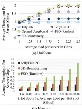
Figure 3: Average per-server throughput for the
Uniform andHotSpotworkloads. The x-axis shows the average load per server which is a product of arrival-rate (per pair), number of servers (512), and average flow size. The result for Hypercube+ is identical to Random and the result for Fat-tree is identical to Jellyfish and are not shown.
flows arrive independently based on a Poisson distribution with aarrival-rateλ/s, with the flow size distribution mea-surements from production DCs [19]. We refer to this as the Uniformworkload. Prior studies have observed hotspots between pairs of racks [19]; thus we consider theHotspot model where in addition to theUniformbaseline, we use a higher arrival-rateλ2and a fixed flow-size of 128MB for a subset of machines chosen as follows [36]. We randomly pick x% of machines, and for each one of them, we pick
x/2% of machines as their destinations with a slight bias [36]; we varyλ2andxin our simulations.
Throughput and Latency. Figure 3(a), shows the average per-server throughput for theUniformworkload. We ob-served that Jellyfish and Fat-Tree architectures are nearly identical and the two FSO-based architectures (Random and Hypercube+) also have the same performance. For ease of presentation, we omit plots for Fat-Tree and Hypercube+.
We see that FSO-based architectures provides 1.7Gbps of average throughput per server, which is significantly higher than 1Gbps Jellyfish/Fattree and 3D-Beamforming, but slightly lower than the 2Gbps Jellyfish/Fattree. As a point of refer-ence, we compute an upper bound on theoptimalthroughput achievable with FSOs. Given a configuration of # FSOs per rack and # SMs per FSO, we compute this bound by esti-mating the minimum possible average shortest-path length; we omit the details due to space limitations. We see that our design performs quite close to the upper-bound of≈2Gbps.
0 0.5 1 1.5 2 2.5 3 3.5 1 3 5 10 15 20 25 30 40 50 A verag e Th ro ug hp ut Per Server (Gb ps)
Number of Switchable Mirrors FSO (HyperCube+) FSO (Random) Optimal (a) Vary #SMs 0 2 4 6 8 10 16 32 48 A verag e Th ro ug hp ut Per Serv er (Gb ps)
FSO's Per Rack
5 SMs per FSO Optimal for 5 SMs/FSO 10 SMs per FSO Optimal for 10 SMs/FSO
(b) Vary #FSOs
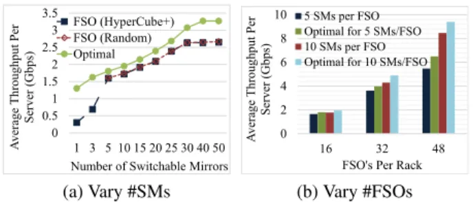
Figure 4: Sensitivity analysis, varying number of FSOs and number of SMs using the baselineUniform work-load
For theHotSpotsworkload in Figure 3(b), as in [36] we use a low baseline load of 0.1Gbps average load per server.7We consider different configurations for the number of hotspots and intensity (i.e.,x%, average load per hotspot) as shown. First, we see that all flexible architectures (FSO-based and 3D-Beamforming) outperform the static Jellyfish (and Fat-Tree) 2Gbps designs. Second, the FSO-based de-sign outperforms 3D-beamforming by large margin (30 to 100%).
We also measured the latency in terms of inter-rack hops per-packet. The average, 95%ile, and max latency for FSO-based proposals were 2.5, 6, and 12 hops respectively (not shown). In comparison, the corresponding numbers for Fat-tree and Jellyfish are 3.9,4,4 and 2.5, 3, 5 hops respectively. We see that in the common case, FSOs provide low latency, but in some very rare cases we incur longer paths.
Sensitivity Analysis. The previous results consider a fixed number of FSOs per rack and SMs per FSO device. In Fig-ure 4, we vary (a) the number of SMs keeping the number of FSOs at 16/rack, and (b) the number of FSOs per rack for 5 and 10 SMs/FSO. (We do not showRandomfor less than 5 SMs, since it does not form a connected graph.) First, we see that the effective per-server bandwidth increases with the increase in SMs, but saturates at around 30 SMs per rack (when we almost get a complete candidate graph). Second, the configuration of 48 FSOs with 10 SMs provides almost 8.5Gbps.
Given our current size estimates, it is actually feasible to place 48 FSOs on each rack; the total cost of this architec-ture is≈$38M. We estimate this assuming a 96-port 10Gb switch (hypothetically) costs $49k (= $25k for the switch + cost for 96 SFP+ modules at $250 each). In compari-son, a 10Gbps Fat-tree architecture would (conservatively) cost around $57M assuming each 48-port 10Gb switch costs $22k (= $10k [8] + cost for 48 SFP+ modules).
5.
DISCUSSION
Rethinking Metrics of Goodness.Traditional metrics such as bisection bandwidth and diameter largely reflect astatic
7
We also tried other baseline loads. FSO outperforms other solu-tions under all scenarios, but the relative gain decreases at higher load as there is less scope for improvement.
perspective of the topology. For the types of flexible net-works we envision, we need to rethink these metrics; e.g., we need a notion ofdynamicbisection bandwidth based on the best achievable bandwidth by somerealizabletopology for a given network partition.
Optimal Topologies. Given new dynamic performance in-dices, we need to reason about the pre-configured alignment of SMs that optimizes these metrics. While the random and extended hypercube designs work well, we do not know if these are provably (near-)optimal. Furthermore, choosing an optimal run-time topology is effectively an online opti-mization problem—given a pre-configured topology, current configuration and traffic patterns, what is the best way to re-configure the network? What makes this challenging is that even the offline version of this problem is intractable.
FSOs for Modularized Data centers. While our current work focuses on the inter-rack fabric, FSOs might also be useful for containerized architectures [17]. This context in-troduces new challenges and opportunities. Specifically, a ceiling mirror is not feasible in outdoor scenarios and we need other mechanisms (e.g., vertically steerable FSOs?) for line-of-sight. At the same time, the coarser aggregation may permit higher switching latencies and thus be amenable to slower (mechanical) steering mechanisms that can provide full reconfigurability.
Multipath and Traffic Engineering. We could further im-prove the performance using multi-path TCP [34] or better traffic engineering [18]. We posit that multi-path TCP has natural synergies with reconfigurability as it can alleviate transient congestion and connectivity issues.
Other Benefits. In addition to the quantitative benefits we explored, FSO-based flexible architectures also offer other qualitative advantages. First, by acting as an enabler for new topologies, it naturally inherits the properties they provide; e.g., random graphs offer incremental expandability [31]. Second, selectively disabling links may also decrease energy costs [21]. Furthermore, by eliminating the wired infrastruc-ture, FSOs can potentially reduce cooling costs by avoiding problems due to airflow obstruction [10].
6.
CONCLUSIONS
We explored an FSO-based inter-rack fabric for data cen-ters, a solution whose benefits have been suggested [9, 15], but has received little attention in depth. We showed that FSOs can be viable with the extensions we propose (e.g., switchable mirrors and pre-configured topologies). Our eval-uations show that FSO-based designs offer good cost vs. per-formance tradeoffs (Table 1) w.r.t. state-of-art solutions; e.g., close to 9 Gbps bisection bandwidth at much less cost com-pared to a Fat-tree, and 90% of the performance for 2 Gbps fat-tree at 70% of the cost. We note that these benefits only represent an early starting point—miniaturization and com-moditization will further improve the cost-performance trade-offs and flexibility that FSO-based designs can offer.
7.
REFERENCES
[1] http: //www.fsona.com/product.php?sec=2500e. [2] http: //discountechnology.com/LightPointe-FlightStrata-G-Optical-Gigabit-Link. [3] http://www.corporatearmor.com/product_ info.php?source=GBUS&products_id= 6340&gclid=COTa4cauurgCFcOe4AodZgYA5g. [4] http://kentoptronics.com/switchable.html. [5] http://www.nanowerk.com/news/newsid= 24852.php#ixzz2ZAueSvFq. [6] http://www.colfaxdirect.com/store/pc/ viewPrd.asp?idproduct=1377. [7] http://www.cisco.com/en/US/prod/ collateral/switches/ps5718/ps6406/ product_bulletin_c25-705278.html. [8] http://www.corporatearmor.com/product_ info.php?source=GBUS&products_id= 5198&gclid=CNPrh9DKvLgCFcee4Aod4j4AVQ. [9] http://conferences.sigcomm.org/hotnets/2009/session1.txt. HotNets-VIII, Scribe Notes. [10] Avoidable mistakes that compromise cooling perfomance.
http://www.mm4m.net/library/Avoidable\ _Mistakes\_that\_Compromise\_Cooling\ _Perfomance.pdf.
[11] M. Al-Fares, , A. Loukissas, and A. Vahdat. A scalable, commodity data center network architecture. InSIGCOMM, 2008.
[12] E. Ciaramella, Y. Arimoto, G. Contestabile, M. Presi, A. D’Errico, V. Guarino, and M. Matsumoto. 1.28-Tb/s (32 ×40 Gb/s) free-space optical WDM transmission system.
Photonics Technology Letters, IEEE, 21(16), 2009. [13] A. Curtis, S. Keshav, and A. Lopez-Ortiz. Legup: using
heterogeneity to reduce the cost of data center network upgrades. InCo-NEXT, 2010.
[14] A. Curtis, W. Kim, and P. Yalagandula. Mahout: Low-overhead datacenter traffic management using end-host-based elephant detection. InINFOCOM, 2011. [15] H. L. Davidson et al. Data center with free-space optical
communications. US Patent 8,301,028, 2012.
[16] N. Farrington. Optics in data center network architecture. http://nathanfarrington.com/papers/ dissertation.pdf.
[17] N. Farrington, G. Porter, S. Radhakrishnan, H. H. Bazzaz, V. Subramanya, Y. Fainman, G. Papen, and A. Vahdat. Helios: a hybrid electrical/optical switch architecture for modular data centers. InSIGCOMM, 2010.
[18] B. Fortz, J. Rexford, and M. Thorup. Traffic engineering with traditional IP routing protocols. IEEE COmmunications Magazine, 2002.
[19] A. Greenberg, J. R. Hamilton, N. Jain, S. Kandula, C. Kim, P. Lahiri, D. A. Maltz, P. Patel, and S. Sengupta. Vl2: a scalable and flexible data center network. InSIGCOMM, 2009.
[20] D. Halperin, S. Kandula, J. Padhye, P. Bahl, and D. Wetherall. Augmenting data center networks with multi-gigabit wireless links. InSIGCOMM, 2011. [21] B. Heller, S. Seetharaman, P. Mahadevan, Y. Yiakoumis,
P. Sharma, S. Banerjee, and N. McKeown. ElasticTree: Saving Energy in Data Center Networks. InProc. NSDI, 2010.
[22] D. Kedar and S. Arnon. Urban optical wireless
communication networks: the main challenges and possible solutions.IEEE Communications Magazine, 42(5), 2004. [23] L. Li. CEO, KentOptronics. Personal Communication.
[24] P. F. McManamon, P. K. Bos, M. J. Escuiti, J. Jeikenfeld, S. Serati, H. Xie, and E. A. Watson. A review of phased array steering for narrow-band electrooptical systems.Proceedings of the IEEE, 2009.
[25] J. Mudigonda, P. Yalagandula, and J. C. Mogul. Taming the Flying Cable Monster: A Topology Design and Optimization Framework for Data-Center Networks. InProc. USENIX ATC, 2011.
[26] L. Mustafa and B. Thomsen. Reintroducing free-space optical technology to community wireless networks. InProc. 19th Americas Conference on Information Systems, Chicago, August, 2013., 2013.
[27] R. N. Mysore, A. Pamboris, N. Farrington, N. Huang, P. Miri, S. Radhakrishnan, V. Subramanya, and A. Vahdat. PortLand: A Scalable Fault-Tolerant Layer 2 Data Center Network Fabric. InProc. ACM SIGCOMM, 2009. [28] L. Popa, S. Ratnasamy, G. Iannaccone, A. Krishnamurthy,
and I. Stoica. A cost comparison of datacenter network architectures. InCo-NEXT, 2010.
[29] J.-Y. Shin, E. G. Sirer, H. Weatherspoon, and D. Kirovski. On the feasibility of completely wireless datacenters. In
Proc. ANCS, 2012.
[30] A. Singla et al. Proteus: a topology malleable data center network. InHotNets, 2010.
[31] A. Singla, C.-Y. Hong, L. Popa, and P. B. Godfrey. Jellyfish: Networking data centers randomly. InNSDI, 2012.
[32] T. Tsujimura, K. Yoshida, T. Kurashima, and M. Mikawa. Trans-window free space optics transmission system. In
Proc. SICE Annual Conference, 2008. IEEE, 2008. [33] G. Wang, D. G. Andersen, M. Kaminsky, K. Papagiannaki,
T. S. E. Ng, M. Kozuch, and M. Ryan. c-through: Part-time optics in data centers. InSIGCOMM, 2010.
[34] D. Wischik, C. Raiciu, A. Greenlagh, and M. Handley. Design, Implementation and Evaluation of Congestion Control for Multipath TCP. Inproceedings of Usenix NSDI, 2011.
[35] K. Yoshida, K. Tanaka, T. Tsujimura, and Y. Azuma. Assisted focus adjustment for free space optics system coupling single-mode optical fibers.Industrial Electronics, IEEE Transactions on, 60(11), 2013.
[36] X. Zhou, Z. Zhang, Y. Zhu, Y. Li, S. Kumar, A. Vahdat, B. Y. Zhao, and H. Zheng. Mirror mirror on the ceiling: flexible wireless links for data centers. InSIGCOMM, 2012.