AS/400e
Networking
AS/400 Communications Management
AS/400e
Networking
AS/400 Communications Management
Contents
Part 1. AS/400 Communications
Management . . . 1
Chapter 1. Print this topic . . . 3
Chapter 2. Configuring AS/400 for
communications . . . 5
Creating a network interface description . . . 5
Creating a network server description . . . 5
Creating a line description . . . 5
Chapter 3. Optimizing communications
performance . . . 7
Improving wide area network performance . . . . 7
Adjusting WAN protocols for optimum AS/400 performance . . . 7
Adjusting the WAN line speed for optimum AS/400 performance. . . 8
WAN line speed considerations for IOPs . . . . 9
Improving local area network performance . . . . 9
Adjusting LANs for optimum communications performance . . . 9
Adjusting LAN lines for optimum communications performance . . . 10
LAN line speed considerations for IOPs . . . . 11
Improving data path performance . . . 11
Considerations for subsystem configuration for error recovery performance . . . 12
Communications performance considerations for interactive jobs . . . 13
Communications performance considerations for batch jobs . . . 14
Mixing interactive and batch jobs on a WAN line 15 Performance considerations for AnyNet communications . . . 15
Subsystems . . . 17
Chapter 4. Communications
applications
. . . 19
User written APPC applications . . . 19
Distributed data management (DDM) . . . 19
Application program interface (API) performance considerations . . . 20
Performance considerations for intersystem communications function . . . 20
Performance considerations for Common Programming Interface Communications . . . 21
Chapter 5. Communicating with host
systems . . . 23
Matching AS/400 parameters for a host system . . 23
Matching AS/400 line description parameters for a host system . . . 23
Matching AS/400 controller description parameters for a host system . . . 25
Matching AS/400 device description parameters for a host system . . . 26
Matching AS/400 mode and class-of-service description parameters for a host system . . . 28
Configuring dependent LU requester (DLUR) . . . 33
Configuring the host controller description . . . 33
Configuring the device descriptions . . . 34
Chapter 6. Communicating with a
remote AS/400 system . . . 35
Matching AS/400 line description parameters for a remote AS/400 system. . . 35
Matching AS/400 controller description parameters for a remote AS/400 system . . . 37
Matching AS/400 device description parameters for a remote AS/400 system . . . 38
Connecting one AS/400 to another AS/400 system 40
Chapter 7. Communicating with remote
workstation controllers. . . 45
Matching AS/400 parameters for 5494 controllers. . 45
Matching AS/400 parameters for a 5494 connected by token-ring . . . 45
Matching AS/400 parameters for a 5494 connected by Ethernet . . . 48
Matching AS/400 parameters for a 5494 connected by frame relay . . . 50
Matching AS/400 parameters for a 5494 connected by SDLC. . . 53
Matching AS/400 parameters for a 5494 connected by X.21 . . . 56
Matching AS/400 parameters for a 5494 connected by X.25 . . . 59
Matching AS/400 parameters for 3x74 controller . . 63
Matching AS/400 parameters for a 3174 controller . . . 63
Matching AS/400 parameters for a 3274 controller . . . 65
Matching AS/400 parameters for finance controllers 67 Matching AS/400 parameters for 470x finance controllers . . . 67
Matching AS/400 parameters for FBSS finance controllers . . . 69
Matching AS/400 parameters for retail controllers 72 Matching AS/400 parameters for 3651 retail controllers . . . 73
Matching AS/400 parameters for 3684 retail controllers . . . 75
Matching AS/400 parameters for 4680/4690 LINE parameter . . . 78
Matching AS/400 parameters for 4680/4690 LINK parameter . . . 78
Matching AS/400 parameters for 4684 retail
controllers . . . 79
Chapter 8. Troubleshooting
communications problems . . . 83
Displaying message queues to solve communication problems . . . 83
Displaying the Product Activity Log to solve communication problems . . . 84
Displaying the Print Error Log to solve communication problems . . . 84
Job logs and communication problems . . . . 84
Solving communication problems using communications trace . . . 85
System service tools and communication problems . . . 86
Trace Common Programming Interface (CPI) Communications (TRCCPIC) command . . . . 86
Solving communication problems using the system problem log . . . 88
Solving communication problems using status information . . . 89
Considerations for system tuning during error recovery . . . 89
Using error messages to aid in error recovery . . . 89
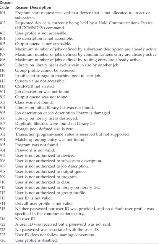
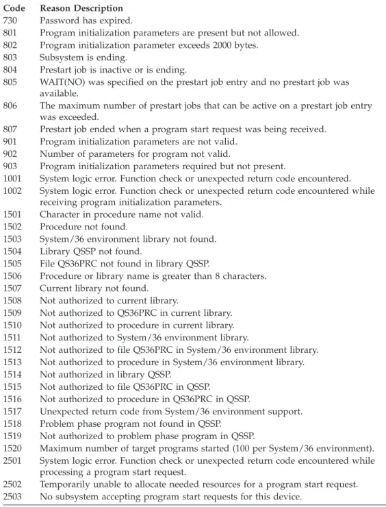
Solving communication problems using reason codes . . . 90
Chapter 9. Networking concepts . . . . 93
Advanced Peer-to-Peer Networking . . . 93
Advanced program-to-program communications . . 94
Dependent LU requester support . . . 94
High-performance routing . . . 95
HPR architecture option sets. . . 95
Internetwork packet exchange support . . . 96
What is Systems Network Architecture . . . 96
What is TCP/IP . . . 96
Chapter 10. Common networking
standards . . . 97
Local area network standards . . . 97
ATM on AS/400 . . . 97
Distributed data interface network. . . 97
Ethernet networks . . . 98
Token-ring networks . . . 98
Wireless network . . . 99
Wide area network standards . . . 99
Asynchronous communications . . . 99
Binary synchronous communications . . . . 100
Frame relay networks . . . 100
Integrated services digital network . . . 100
Synchronous data link control network . . . . 101
X.25 network . . . 101 X.21 network . . . 102 | || || || || || || || || || || || || || || ||
Part 1. AS/400 Communications Management
Display or print a PDF version of this topic.
The AS/400 is an extremely versatile system for networking technologies,
supporting a broad range of communication protocols. Protocols that are supported include TCP/IP, APPC, APPN, HPR, Remote workstation, asynchronous, and binary synchronous communications.
AS/400 communications configuration is done by either manually or automatically creating a set of configuration objects that represent the local and remote systems that are to communicate. The types of objects required for a communications configuration vary, depending on the type of communications being configured.
Many factors can affect the performance of the AS/400 in a communications environment. To achieve the best performance with your particular environment review the topics, Optimizing communications performance, and Communications applications.
You can configure your AS/400 system to communicate with another AS/400 system, a non-AS/400 system, or a remote controller. For information on how to do this, see the following:
v Communicating with host systems
v Communicating with a remote AS/400 system v Communicating with remote workstation controllers
Communication problems are inevitable and will probably be an issue as you manage your network. If you suspect that you are having communication problems, review the topic Troubleshooting communication problems.
Before beginning to work with AS/400 communications, you may want to review the topics, “Chapter 9. Networking concepts” on page 93 and “Chapter 10.
Common networking standards” on page 97. Here, you can find information related to some of the technologies common to deploying modern networking solutions in an AS/400 environment.
© Copyright IBM Corp. 1998, 2000
1
| | | |
Chapter 1. Print this topic
You can view or download a PDF version of this document for viewing or
printing. You must have Adobe®Acrobat®Reader installed to view PDF files. You
can download a copy from Adobe. .
To view or download the PDF version (721 KB or 110 pages), select AS/400 communications management.
To save a PDF on your workstation for viewing or printing:
1. Open the PDF in your browser (click the link above).
2. In the menu of your browser, click File.
3. Click Save As...
4. Navigate to the directory in which you would like to save the PDF.
5. Click Save.
Chapter 2. Configuring AS/400 for communications
Follow these steps to configure your AS/400:
1. Depending on the type of hardware you have, you may need to refer to the following topics:
v Creating a network server description v Creating a network interface description
2. You define lines by creating line descriptions. Depending on your hardware, the lines may be attached to a network server, or a network interface.
Creating a network interface description
Network interface descriptions for asynchronous transfer mode (ATM), frame relay, and integrated services digital network (ISDN) protocols describe the
communications interface.
To create a network interface description, do the following:
1. Type one of these commands on any AS/400 command line for the type of network interface you are creating and press F4:
v Create Network Interface (ATM) (CRTNWIATM)
v Create Network Interface (Frame Relay Network) (CRTNWIFR) v Create Network Interface Description for ISDN (CRTNWIISDN) 2. Use the on-line help information to choose the correct parameter values.
3. Press Enter. The network interface description is created.
Creating a network server description
A network server description describes which Integrated PC Server the local area network (LAN) and the application will be using.
To create a network server description, do the following:
1. Type the Create Network Server Description (CRTNWSD) command on any AS/400 command line and press F4.
2. Use the on-line help information to choose the parameter settings.
3. Press Enter. The network server description is created.
Creating a line description
You create line descriptions to describe the physical line connection and the data link protocol to be used between the AS/400 system and the network.
To create line descriptions, do the following:
1. Type one of these commands on any AS/400 command line to define the type of line you are creating and press F4.
v Create Line Description (Ethernet) (CRTLINETH)
v Create Line Description (Distributed Data Interface (DDI)) (CRTLINDDI) v Create Line Description (Frame Relay) (CRTLINFR)
v Create Line Description for (IDLC) (CRTLINIDLC)
v Create Line Description (Synchronous Data Link Control (SDLC))
(CRTLINSDLC)
v Create Line Description (Token-ring) (CRTLINTRN) v Create Line Description (Wireless) (CRTLINWLS) v Create Line Description (X.25) (CRTLINX25)
2. Use the online help information to choose the correct parameter values.
Chapter 3. Optimizing communications performance
Many factors can affect the performance of AS/400 application programs. To achieve the best performance with your particular communications environment, you may want to review these topics:
v Improving wide area network (WAN) performance. v Improving local area network (LAN) performance. v Improving data path performance.
Improving wide area network performance
To achieve better performance with your AS/400 when communicating in a wide area network (WAN), you need to consider the following:
v “Adjusting WAN protocols for optimum AS/400 performance”
v “Adjusting the WAN line speed for optimum AS/400 performance” on page 8 v “WAN line speed considerations for IOPs” on page 9
Adjusting WAN protocols for optimum AS/400 performance
Wide area network (WAN) protocols affect the communications performance on AS/400. Let us use X.25 for our example. For each X.25 communications controller, the AS/400 has some processing limitation for the line, the line speed, and the total number of virtual circuits that can be used. Performance degradation can be reduced by observing these limitations.
To optimize AS/400 performance for wide area networks, perform these tasks:
v Reduce the total number of frames by using larger frames.
v To take advantage of these large frame sizes, change the MAXFRAME parameter
on the line description (LIND) to reflect the maximum value. For X.25, increase the DFTPKTSIZE and MAXFRAME parameters to their maximum value.
v Configure a WAN line as full-duplex to provide you with a higher throughput
for applications that can take advantage of this mode. This can also provide higher throughput for multiple users.
v Increase frame relay to capacity.
The data rate for a given protocol may increase as frame size increases. Under these circumstances, the central processing unit (CPU) and the input/output processor (IOP) do not do as much processing. Fewer and larger frames also make more efficient use of the communications line (higher effective data rate) because of fewer overhead bytes and line turn-arounds.
Frame relay has equivalent performance over RS449, X.21, and V.35 assuming equal line speeds and conditions. Frame relay performance (CPU time) is similar to or slightly better than Synchronous Data Link Control. For properly tuned large transfer applications, the CPU and IOP have no problem using the line speed to capacity.
For information about configuring AS/400 communications, see the
Communications Configuration book.
© Copyright IBM Corp. 1998, 2000
7
| | |
Adjusting the WAN line speed for optimum AS/400
performance
In many cases, the communications line is the largest contributor to overall
response time in the wide area network (WAN). Therefore, you should closely plan and manage its performance. In general, having the appropriate line speed is the key consideration for gaining the best performance.
To adjust the line speed for your wide area network, perform these tasks:
v Check the difference in performance between half-duplex utilization and
full-duplex utilization on the line description.
v For interactive environments, keep line use below 30% to maintain predictable
and consistent response times. Exceeding 50% line use usually slows down response time. The line use can be measured with the AS/400 performance tools.
v For large transfer environments, or for environments in which only a small
number of users are sharing a line, increase line use to allow for acceptable response times.
v The CPU usage for fractional T1 support and other high-speed WAN
connections is similar to any other line that runs the same type of work. As the speed of a line increases from a traditional low speed to a high-speed or full T1/E1/J1 speed, performance characteristics may change as follows:
– With interactive transactions, performance may be slightly faster. – With a large transfer, performance may be significantly faster.
– With a single job, performance may be too serialized to use the entire bandwidth.
– With high throughput, performance is more sensitive to frame size.
– With high throughput, performance is more sensitive to application efficiency. – With synchronous data link control (SDLC), the communications controller
CPU usage increases because of polling.
Additional considerations for adjusting the wide area network line speed are the following:
v A common misconception about the line speed of each attached communications
line is that central processing unit (CPU) resource is used in a uniform fashion. Exact statements cannot be made about the number of lines that any given AS/400 model can support.
v Most communications applications use a lot of CPU resource (to process data, to
support disk input and output) and communications line resource (to send and receive data or display I/O). The amount of line resource that is used is proportional to the total number of bytes that are sent or received on the line. Some additional CPU resource is used to process the communications software to support the individual sends (puts or writes) and receives (gets or reads). Communications input/output processor resource is also used to support the line activity.
v When a single job is running disk operations or doing non-overlapped CPU
processing, the communications link is idle. If several sessions transfer concurrently, then the jobs are more interleaved and make better use of the communications link.
v Polling is an important consideration for synchronous data link control (SDLC)
environments. All SDLC polling is handled by the communications controller and is governed by parameters in both the line and controller descriptions.
v For information about AS/400 configuration, see the Communications
v For more information about performance tools, see the Performance Tools for
AS/400 book.
WAN line speed considerations for IOPs
When configuring a communications controller, you should consider both subsystem storage and aggregate line speed. Subsystem storage is the amount of storage available on the communications controller. Aggregate line speed is the sum of individual lines speeds that are attached to the communications controller.
The following information can help you understand network line speed considerations for input/output processors (IOPs).
v For interactive environments, you should not exceed 60% use on the
communications IOP. Exceeding this threshold in a large transfer environment or with a small number of concurrent users may still offer acceptable performance. Use the AS/400 performance tools to get the utilization.
v You can attach multiple IOPs to an AS/400 system. The maximum number of
IOPs that can be attached is determined by the AS/400 model. It is important to distribute the work load across several IOPs if the performance capabilities of a single IOP is exceeded.
v Even though an IOP can support certain configurations, a given AS/400 model
may not have enough system resource (for example, CPU processing capacity) to support the work load over the lines.
v The use of larger frames generally improves large transfer performance in terms
of capacity for the communications IOP and in terms of system response time. The amount of time that the IOP spends processing a larger frame is only slightly more than the amount needed to process a smaller frame. If you use larger frames to transfer a single system message or block of data, decreases the total number of frames required to complete the transfer.
v The values for IOP use in synchronous data link control (SDLC) environments
do not necessarily increase consistently with the number of work stations or with the workload. An IOP can spend more time polling when the application is not using the line. It is possible to see a relatively high IOP use at low
throughput levels.
v For information on AS/400 configuration, see the Communications
Configuration book.
v For more information on performance tools, see the Performance Tools for
AS/400 book.
Improving local area network performance
To achieve better performance with your AS/400 when communicating in a local area network (LAN), you need to consider the following.
v “Adjusting LANs for optimum communications performance”
v “Adjusting LAN lines for optimum communications performance” on page 10 v “LAN line speed considerations for IOPs” on page 11
Adjusting LANs for optimum communications performance
Local area networks (LAN) affect the communications performance on AS/400. Improvements to LAN input/output (IOPs) in the areas of increased central processing unit (CPU) time, IOP capacity, and support of IOP assist make them
more efficient. This efficiency allows advanced program-to-program
communications (APPC) to send request units to the IOP, passing the processing cost of processing frame to the IOP.
The following information can help you understand the protocol considerations for local area networks.
v A Data Link Control (DLC) can achieve a significantly higher data rate than
other supported line types. This is due to the desirable combination of having a high media speed along with large frame sizes.
v When several sessions use a line or LAN concurrently, the aggregate data rate
may be higher than when only one session is used.
v To achieve good performance in a multi-user interactive LAN environment, you
should manage the number of active users so that LAN media use does not exceed 50%. (A 25% utilization is recommended for Ethernet environments because of media collisions that causes the program to loop). Operating at higher utilization may decrease response time because of excess queueing time for the line. In a large transfer environment in which a small number of users contend for the line, a higher line use may still offer acceptable performance.
For more information about AS/400 configuration, see the Communications
Configuration book.
Adjusting LAN lines for optimum communications
performance
Several parameters in the line description (LIND) and the controller description (CTLD) play an important role in system performance that you can change.
The following information can help you to understand the line considerations for local area networks.
v MAXFRAME on the line description (LIND) and the controller description
(CTLD): Maximizing the frame size in a LAN environment supplies the best performance for large transfers. A large frame size does not negatively affect performance for small transfers. Configure both the AS/400 system and the other link station for large frames. Otherwise, of the two maximum frame size values, the smaller is used when you transfer data. Bridges may also limit the maximum frame size. You should change the default value from 1994 to a larger size.
v LANMAXOUT on the CTLD (for advanced program-to-program
communications (APPC) environments): This parameter governs how often the sending system waits for an acknowledgment. The LANACKFRQ parameter value on one system should never have a greater value than the LANMAXOUT parameter value on the other system. The parameter values of the sending system should match the values on the receiving system.
v Setting appropriate values for the LANMAXOUT parameter along with the LAN
acknowledgment frequency (LANACKFRQ) parameter for both the sending stations and receiving stations is essential for optimal performance. Other values may decrease throughput by 50% or even more if conditions trigger time-outs.
v LANWDWSTP for advanced program-to-program communications (APPC) on
the controller description (CTLD): If there are network congestion or overruns to certain target system adapters, then increasing the value from the default of *NONE to 2 or more may improve performance.
In general, setting the LANMAXOUT parameter value to *CALC or 2 offers the best performance for interactive environments and adequate performance for larger transfer environments.
v For large transfer environments, changing the LANMAXOUT value may
significantly increase performance. As starting points, use the following guidelines:
– When you are communicating with a recent model personal computer, increase the LANMAXOUT parameter, but keep the LANACKFRQ parameter set to *CALC. For older models of personal computers, use *CALC for both values to limit buffer overruns.
– If LANACKFRQ and LANMAXOUT parameter values are changed without noticeable performance improvements, change the values back to *CALC.
For more information on AS/400 communications, see the Communications
Configuration book.
LAN line speed considerations for IOPs
When configuring an AS/400 system with communications lines and local area networks (LANs), you should not overload an input/output processor (IOP) to prevent possible system performance bottlenecks.
The following information can help you to understand the line speed considerations for IOPs.
v The integrated PC server performance is similar to the 2619 and the 2617 IOPs
for host LAN functions. For send and receive scenarios, performance is equivalent. For large transfers, the 6506 IOP is slightly faster than the 2619 TRLAN IOP, but slightly slower than the 2617 Ethernet IOP. These differences are not significant enough to choose one over the other.
v The 100 Mbps Ethernet support provides the best LAN performance. The IOP
can be optimally configured to have an aggregate transfer rate of 27 Mbps. Multiple concurrent large transfers may be required to drive at that rate.
v When analyzing communications performance that includes the 2619 TRLAN
IOP, you should be aware that resources other than the IOP use can become the bottleneck.
v You should have the highest capacity IOP available for file serving. You should
have the highest capacity IOP available for environments that use many communications input and output operations for each transaction. The highest capacity IOP also minimizes the overall response time.
See the following references for more detail:
v For more information about AS/400 communications, see the Communications
Configuration book.
v For more information on IOP performance, see the Performance Tools for
AS/400 book.
Improving data path performance
To assess the performance of your data path, you may want to review the following topics:
v Considerations for subsystem configuration for error recovery performance v Communications performance considerations for interactive jobs
v Consider communications performance for batch jobs v Mix interactive and batch jobs on a wide area network line v Performance considerations for AnyNet communications v Subsystems
Considerations for subsystem configuration for error recovery
performance
Each piece of work that runs on the AS/400 system is called a job. Each job is a single, identifiable sequence of processing actions that represents a single use of the system. The basic types of jobs performed are interactive jobs, batch jobs, spooling jobs, autostart jobs, and prestart jobs.
Jobs that run in subsystems do all work that is performed on the AS/400. As the number of users on the system increases, it becomes important for you to consider how the communications and interactive subsystems should be configured.
The configuration of subsystems has little impact in normal data path operations. However, multiple subsystems can provide multiple processes to do cleanup and recovery when error conditions occur. This can result in improved performance.
As the number of users on the system increases, you must consider the importance of how subsystems are configured:
v Consider limiting the number of devices that are serviced by a single subsystem.
Between 200 and 300 devices for each subsystem are recommended. Use the following recommendations to divide these users:
– The number of users in any given subsystem – The connectivity used to access the system – The type of work the users do
– The geographic location of the users
v Create additional communications and interactive subsystems to split the work
into multiple subsystems.
v The work that is performed in the QCMN subsystem is for connecting and
disconnecting from the system. Error recovery considerations are important in the configuration of the communications subsystem.
v To prevent a subsystem from ever allocating a device, ensure that there are no
workstation or type entries for the devices that you do what allocated by that subsystem.
v Only use the AT(*ENTER) option if you must allow jobs to transfer into that
subsystem.
v For each subsystem you have defined, you need to identify which users will run
in which subsystems. Use the Add Work Station Entry (ADDWSE) command and the Remove Work Station Entry (RMVWSE) command. You can set up work stations entries that identify which devices that subsystem should allocate, as well as which devices a subsystem should not allocate.
Note: You can use the ADDWSE commands while the subsystem is active.
However, subsystems do not reallocate device locks dynamically. Eventually, it may be necessary to end and restart the subsystems to have the device locks allocated to the desired subsystem.
To specify the devices a communications subsystem should allocate:
ADDCMNE SBSD(libname/sbsname) DEV(devname*) MODE(modename)
To specify the devices a communications subsystem should not allocate:
Note: Database and file servers run only in QSERVER. Do not attempt to allocate sessions running over the QSERVER mode description. You can do this by adding the following communication entry to your subsystem:
ADDCMNE (SBSD(libname/sbsname) DEV(devname*) MODE(QSERVER) MAXACT(0)
See the following example for a way of configuring your communications subsystem.
Example: Communications subsystem configuration
1. Create a duplicate of QCMN:
CRTDUPOBJ OBJ(QCMN) FROMLIB(QSYS) OBJTYPE(*SBSD) TOLIB(MYLIB) NEWOBJ(MYCMN)
2. Set up the communication entries:
ADDCMNE SBSD(MYLIB/MYCMN) DEV(PC*)
ADDCMNE SBSD(MYLIB/MYCMN) DEV(PC*) MODE(QSERVER) MAXACT(0) ADDCMNE SBSD(QSYS/QCMN) DEV(PC*) MODE(QPCSUPP) MAXACT(0)
3. If desired, update your system startup program to start your new subsystems automatically.
Communications performance considerations for interactive
jobs
An interactive job is one that uses a keyboard and character-type display. If a job needs the user to type on the keyboard and display character results, that job is probably considered interactive. Interactive in this sense means that the job and the user depend on each other to get the work done.
To optimize communications performance for interactive jobs, consider the following:
v Attach work stations through communications requires more CPU overhead than
5250 local workstations.
v Use a twinaxial controller to provide better performance than an American
National Standard Code for Information Interchange (ASCII) controller.
v Keep the line utilization below 30 percent for best performance when interactive
users are attached. This will maintain predictable and consistent response times. Exceeding 50 to 60 percent line utilization will usually cause unacceptable response times.
If your system has interactive users who are connected many different ways, you should consider configuring your interactive subsystems to separate the users. Local workstation, remote workstations, 5250 display station pass-through, or Telnet are some examples of these types of connections that should be separated. When you configure interactive subsystems, identify how you want the interactive users to be separated and create the appropriate subsystem descriptions.
During error recovery, when many users risk losing their sessions at one time, an interactive subsystem can be very busy performing device recovery. This device recovery can adversely affect the work of other users in the subsystem who would otherwise be unaffected by the failure. Therefore, you may need to change how the interactive subsystems are configured. However, multiple subsystems can provide multiple processes to do cleanup and recovery when error conditions occur. This can result in improved performance.
The example below shows how to configure an interactive subsystem to allocate devices that begin with devname* and present a signon display on those display devices:
Chapter 3. Optimizing communications performance
13
| | | | | | | | | | |ADDWSE SBSD(libname/sbsname) WRKSTNDEV(devname*) AT(SIGNON)
Use the following example to configure an interactive subsystem so that the device name devname* is not allocated and a signon display does not appear.
ADDWSE SBSD(libname/sbsname) WRKSTNDEV(devname*) AT(*ENTER)
Adding workstation entries with AT(*ENTER) allows you to use the Transfer Job (TFRJOB) function into that subsystem. If the TFRJOB function is not required or necessary, there is no need to add the workstation entries with AT(*ENTER).
To specify the devices an interactive subsystem should allocate when the subsystem is started:
ADDWSE SBSD(libname/sbsname) WRKSTN(devname*) AT(*SIGNON)
To specify the devices an interactive subsystem should not allocate when the subsystem is started:
ADDWSE SBSD(libname/sbsname) WRKSTN(devname*) AT(*ENTER)
v See the following example for a way of configuring your interactive subsystem.
Example: Interactive subsystem configuration
1. Create a subsystem description:
CRTSBSD SBSD(MYLIB/MYINTER) POOLS((1 *BASE) (2 *INTERACT))
2. Create a class
CRTCLS CLS(MYLIB/MYCLASS) RUNPTY(20)
3. add routing entries to your subsystem:
ADDRTGE SBSD(MYLIB/MYINTER) SEQNBR(10) CMPVAL(QCMDI) PGM(QSYS/QCMD) POOLID(2) ADDRTGE SBSD(MYLIB/MYINTER) SEQNBR(9999) CMPVAL(*ANY) PGM(QSYS/QCMD) POOLID(2)
4. Create a job queue, and add the job queue entry to your new subsystem:
CRTJOBQ JOBQ(MYLIB/MYJOBQ)
ADDJOBQE SBSD(MYLIB/MYINTER) JOBQ(MYLIB/MYJOBQ) MAXACT(200)
5. Set up the workstation name entries. Remove all the *ALL workstation type entries first, and then add the appropriate workstation name entries:
RMVWSE SBSD(QSYS/QINTER) WRKSTNTYPE(*ALL) ADDWSE SBSD(QSYS/QINTER) WRKSTN(QPADEV*) ADDWSE SBSD(MYLIB/MYINTER) WRKSTN(PC*)
6. If desired, update your system startup program to start your new subsystems automatically.
Communications performance considerations for batch jobs
Each piece of work run on the AS/400 system is called a job. Each job is a single, identifiable sequence of processing actions that represents a single use of the system. The basic types of jobs that are performed are interactive jobs, batch jobs, spooling jobs, autostart jobs, and prestart jobs.
Batch jobs are predefined groups of processing actions that are submitted to the system to be performed with little or no interaction between the user and the system. Batch jobs can be tuned for optimized performance.
To optimize batch jobs for communications, consider the following:
v Break the application into pieces and having multiple batch threads (jobs)
operate concurrently.
v Reduce the number of open and close operations, input and output operations. v If you have a considerable amount of main storage available, consider using the
Set Object Access (SETOBJACC) command. This command preloads the
| | | | | | | | | | | | | | | | | | |
complete database file, database index, or program into the assigned main storage pool if sufficient storage is available. The objective is to improve performance by eliminating disk-read/write operations.
v Try to limit the number of communications input and output operations by
doing fewer (and perhaps larger) application sends and receives when communications lines are used.
v Block the data in the application. Try to place the application on the same
system as the frequently accessed data.
For more information about batch job performance, see the Communications
Management book.
Mixing interactive and batch jobs on a WAN line
When interactive users and large transfers are running on a communications line concurrently, you may need to change configuration parameters. You should be able to configure AS/400 communications to work with interactive and batch jobs.
To mix interactive and batch jobs on a wide area network (WAN) line, consider the following to keep interactive performance acceptable:
v Use Advanced Peer-to-Peer Networking (APPN) transmission priority to
prioritize the interactive user’s transfer over that of the large transfer. This is the preferred method to transfer batch and interactive jobs.
v Change the request/response unit size to a lower value for the large transfer.
This parameter setting optimizes response time at the expense of large transfer performance.
v Reduce the pacing values for the large transfer to slow it down, which allows
the interactive users more windows for getting on the line.
Note: The overall central processing unit time increases for the large transfer.
For more information about AS/400 communications, see the Communications
Configuration book.
Performance considerations for AnyNet communications
AnyNet communications is a good performance factor for you to consider. It is more expensive to use than any of the OS/400 protocols because you spend twice as much to run two protocols.
To optimize AnyNet performance, consider the following:
v For send and receive pairs, the most efficient use of an interface is with its own
protocol stack. That is, intersystem communications function (ICF) and common programming interface communications (CPI Communications) perform the best with advanced program-to-program communications (APPC). There is additional CPU time when the crossover between the protocols processes.
v Each communications interface performs differently depending on the scenario.
ICF and CPI Communications perform the best with APPC.
Note: An alternative to AnyNet communications is to have SNA and TCP/IP running parallel or over the same lines in your network. Hence, performance implications can be surpassed by not using AnyNet.
For more information about AnyNet/400 sockets, see the book Sockets
Programming .
Setting up the AnyNet environment
AnyNet/400 is an AnyNet family product. These products allow you to use application programs that are written for a certain communications protocol but also run over non-native communications protocols without changing (or even re-compiling) the application program. The choice of the destination address controls whether the request is sent over the native protocols or through the AnyNet code and on to a non-native protocol.
To configure Transmission Control Protocol/Internet Protocol (TCP/IP) over advanced program-to-program communications (APPC), you need to take two basic actions:
1. Identify the set of IP addresses to route over the SNA network.
2. Tell the system how to convert the IP address to the SNA format.
For more information about APPC Over TCP/IP Configuration, see the APPC
Programming book.
For more information about IPX Support, see the Internetwork Packet Exchange
(IPX) Support.
For related information about AnyNet, see:
“AnyNet communications for the AS/400 system”
“Performance considerations for AnyNet communications” on page 15
AnyNet communications for the AS/400 system
AnyNetis an IBM implementation of the Multiprotocol Transport Networking (MPTN) architecture, such as AnyNet/2 and AnyNet/Multiple Virtual Storage (MVS). AnyNet capability allows applications and associated services that use application programming interfaces, such as sockets, intersystem communications function (ICF), or CPI Communications, the flexibility to use alternative network protocols, such as Systems Network Architecture (SNA) or TCP/IP. AnyNet is a family of products that allow applications that are written for one type of network protocol to run over a different type of network protocol. For example, without AnyNet, your choice of application program interface (API) dictates your choice of network protocol, or your choice of network protocol dictates your choice of APIs.
AnyNet allows you to mix and match applications with network protocols. In fact, you can do this without changing your application programs. Your destination address (such as a remote location) determines the type of network protocol to use.
v AnyNet/400 Sockets
This support converts TCP/IP addresses to SNA addresses that are based on tables that are configured by the network administrator. Programs supported include File Transfer Protocol (FTP), Simple Mail Transfer Protocol (SMTP), Simple Network Management Protocol (SNMP), PING, and user-written sockets programs.
– TCP/IP over SNA – TCP/IP over IPX
v AnyNet/400 APPC (advanced program-to-program communications)
This support allows programs that are written to traditional APPC APIs (such as ICF, CPI-Communications, and CICS/400) to be run over non-APPC networks.
The application program uses Location names to specify the source and destination address. A TCP/IP domain name server converts these location names to IP addresses. Programs supported include distributed data
management (DDM), Distributed Relational Database Architecture (DRDA), SNA distribution services (SNADS), display station pass-through, Client Access, user-written CPI-Communications programs, and user-written ICF programs . – APPC over TCP/IP
– APPC over IPX
For more information about using both AnyNet and nonAnyNet sockets, see the
Sockets Programming book.
Subsystems
A subsystem is a single, predefined operating environment through which the system coordinates work flow and resource usage. OS/400 can contain several that are independent operating subsystems. The run-time characteristics of a subsystem are defined in an object that is called a subsystem description. IBM supplies several subsystem descriptions that can be used with or without modification:
QINTER
Used for interactive jobs
QBATCH
Used for batch jobs
QBASE
Used for both interactive and communications batch jobs
QCMN
Used for communications batch jobs
QSERVER
File server system
QSYSWRK
Used for general system work
QUSRWRK
This is the default subsystem used for TCP/IP Client Access Host Servers that used to run in QSYSWRK.
A new subsystem can also be defined with the Create Subsystem Description (CRTSBSD) command.
For more information about creating subsystems, see the Work Management book.
Chapter 4. Communications applications
Communications applications that are used in an APPC (advanced
program-to-program) environment are also available to be used in an APPN and HPR environment; only the method by which data is transported is changed. APPC delivers the data from applications higher in the SNA layers down to APPN for transportation through the network. User-written APPC applications and distributed data management (DDM) are fully supported in an APPN and HPR environment. The topic, Application programming interface (API) performance considerations gives a more complete discussion of APPC applications.
When you encounter problems that indicate that the route to the remote location cannot be found, you can attempt to make the connection again with the Start Pass-Through (STRPASTHR) command. See the topic, Solving remote
communication problems using STRPASTHR for more information.
For information on Connecting Windows 95/NT Clients to your AS/400, see Client Access.
User written APPC applications
APPN performs many functions in a communications environment. Therefore, it is important to consider time-out parameters in APPC programs which use ICF. In particular, it may be important to increase the WAITFILE parameter for these applications so that they do not time-out while waiting for APPN functions to be performed.
APPN function is transparent to APPC programs using APPN take advantage of the following routing functions:
v Non-adjacent nodes appear adjacent and so APPC programs may communicate
directly to programs in non-adjacent nodes (without any APPC programs on the intermediate nodes).
v Performance is improved for APPC programs with session endpoints that are
not physically adjacent in the network.
v APPC programs may communicate directly to programs in nodes in an adjacent
APPN network through network nodes.
Distributed data management (DDM)
DDM is a function of the operating system that allows an application program or user on one system to use database files stored on remote systems. The systems must be connected by a communications network, and the remote systems must also be using DDM.
DDM on the AS/400 allows application programs or users to:
v Access data files that reside on remote systems (target systems). The remote
systems can also access data files on the local AS/400 system.
v An application can add, change, and delete data records in a file that exist on a
target system.
v Create, delete, or rename files on a remote system. v Copy a file from one system to another.
© Copyright IBM Corp. 1998, 2000
19
| | | | | | | |
When DDM is in use, neither the application program nor the program user needs to know if the file that is needed exists locally or on a remote system. Remote and local file processing are essentially handled the same way.
Application program interface (API) performance considerations
To achieve better performance with your AS/400, you need to consider the application programming interface (API) available on the AS/400. To optimize APPC performance, consider the following:
v Using larger sends for a given large transfer (record sizes) provides a higher
application data rate and decreases CPU time. With the larger record size, the CPU has less processing to do because there are fewer application reads and writes to transfer the same amount of data.
v If a value of *CALC is selected for maximum Systems Network Architecture
(SNA) request/response unit (RU), the system selects an efficient size compatible with the frame size. The frame size is on the line description that you choose. Changing the RU size to a value other than *CALC may negate the performance feature.
v Compression with APPC should be used with caution and only for slower speed
wide area network (WAN) environments. Many suggest that compression should be used with speeds 19.2 kbps and slower.
v If you are doing tasks that include repetitive, small puts; better performance is
achieved if you use ICF or CPI Communications.
See the following topics for a more complete discussion of APPC applications:
v Performance considerations for Intersystem Communications Function v Performance considerations for Common Programming Interface
communications
For information about AS/400 communications, see the Communications
Configuration book.
For more information about CICS/400, see the CICS/400 Administration and
Operations Guide.
Performance considerations for intersystem communications
function
You can use intersystem communications function (ICF) to write application programs that you want to communicate with advanced program-to-program communications (APPC). ICF also provides program-to-device communications between the AS/400 system and hardware devices. You must determine which system is to send data first before you write the program. ICF data management handles the communication functions and the data for your program. In particular, ICF should be used to do tasks that include repetitive, small inputs.
To optimize ICF performance, consider the following:
v Eliminate unused record formats.
v Use separate record formats instead of multipurpose record formats with option
indicators.
v Code to use the same record format for repeated operations. v Set the maximum program devices equal to 1.
v Use a nonshared file.
v Use a separate indicator area.
v Use the Request to Send keyword only when necessary.
v Use the Invite Only keyword when soliciting input from multiple devices,
otherwise use the Read keyword instead.
v If using the Invite keyword to solicit from multiple program devices, follow it
with a Read-from-invited operation, not a Read operation.
To create device descriptions to get your system set up for ICF, do the following:
1. Type the appropriate Create Device Description commands on the AS/400 command line and press F4.
2. Use the online help information to choose the parameter values.
3. Press Enter. The device description is created.
For more information about ICF, see
v “Application program interface (API) performance considerations” on page 20 v ICF Programming
Performance considerations for Common Programming
Interface Communications
You can use Common Programming Interface Communications (CPI
Communications) to write application programs that you want to communicate with advanced program-to-communications (APPC). The interface makes use of the System Network Architecture (SNA) LU (logical unit) 6.2 architecture to do the following:
v Establish a conversation v Send and receive data v Exchange control information v End a conversation
v Notify a partner program of errors.
Intersystem communications feature (ICF) and CPI Communications programs have similar performances for small data transfers.
To optimize CPI Communications application programs, do the following:
v Minimize the use of flush and confirm.
v Receive a compile record and parse it in your buffer. v Do not use multiple receive calls to receive a single record. v Use Request-to-Send only when necessary.
To add or change communications entries to get the system set up for CPI Communications, do the following:
1. Type appropriate command on the AS/400 command line and press F4.
v Add Communications Entry (ADDCMNE) v Remove Communications Entry (RMVCMNE) v Change Communications Entry (CHGCMNE)
2. Use the online help information to change, add, or remove parameter values.
3. Press Enter. The communications entries are added, changed or removed.
For more information about configuring CPI Communications, see:
v “Application program interface (API) performance considerations” on page 20 v CICS/400 Administration and Operations Guide
Chapter 5. Communicating with host systems
You can configure the AS/400 system to communicate with a host system by matching AS/400 parameters.
Another option for AS/400 users is Dependent LU Requester Support (DLUR). DLUR allows dependent secondary logical units (LU 0, 1, 2, and 3) an entry point into the APPN network. DLUR support gives the appearance of having an adjacent connection to VTAM, but allows traversing the APPN network through
intermediate nodes. To configure DLUR, see the page Configuring Dependent LU Requester (DLUR).
Matching AS/400 parameters for a host system
You can configure the AS/400 system to communicate with a host system. This configuration requires the coordination of parameters and values. The list contains only those configuration prompts and parameters that require coordination on both the AS/400 and the host system. In addition, some of the parameters that are listed may not apply to your particular configuration.
For examples of connecting an AS/400 to a host system, see “Examples: Connecting AS/400 to a host system” on page 28.
For information about configuring host systems, see the manuals VTAM Installation
and Resource Definition, SC23-0111, and Network Control Program Resource Definition Reference, SC30-3254.
v “Matching AS/400 line description parameters for a host system”
v “Matching AS/400 controller description parameters for a host system” on
page 25
v “Matching AS/400 device description parameters for a host system” on page 26 v “Matching AS/400 mode and class-of-service description parameters for a host
system” on page 28
v For more information on AS/400 parameters, see Communications
Configuration.
Matching AS/400 line description parameters for a host
system
You must match host system communications configuration parameters with AS/400 values. A description of these AS/400 values are in the following table. For information about configuring host systems, see the manuals VTAM Installation and
Resource Definition, SC23-0111, and Network Control Program Resource Definition Reference, SC30-3254.
You can specify some host system parameters on multiple definition statements, such as the GROUP, LINE, PU, and LU. The following table lists only the lowest level definition statement that is used by the host system.
To configure an AS/400 to a host system:
v See “Examples: Connecting AS/400 to a host system” on page 28 for an example
of connecting an AS/400 to a host system.
v Use the following table for the line description parameter.
AS/400 Prompt
AS/400 Parameter
Host Definition
Statement Host Parameter
Local adapter address ADPTADR PATH DIALNO
Host DIALNO parameter is a concatenation of: SSAP/DSAP/remote-adapter-address.
AS/400 CRTLINTRN command ADPTADR value must match the remote-adapter-address portion of the host DIALNO parameter. The DSAP portion of the DIALNO parameter must correspond to the SSAP value specified on the AS/400 controller description.
PU MACADDR
For 9370/LAN only, the AS/400 line description ADPTADR must match the host MACADDR parameter. MACADDR can be coded as an 8- or 12-digit hexadecimal number; the 8-digit variation assumes4000in the first four positions (4000xxxxxxxx).
Connection type CNN GROUP DIAL
If the AS/400 line description CNN parameter is *SWTPP or *SHM, DIAL=YES must be specified for the host system; if CNN is *MP or *NONSWTPP,
DIAL=NO must be specified.
If CNN(*MP) is specified, the SERVICE
macroinstruction must be used to specify the sequence in which stations are served.
Exchange identifier EXCHID PU IDBLK, IDNUM
The AS/400 block number (digits 1-3 of the EXCHID) is always056. The remaining 5 digits (based on the system serial number if *SYSGEN is used) are specified in the IDNUM parameter.
Line speed LINESPEED LINE SPEED
Line speeds specified for each system must match.
Maximum frame size MAXFRAME PU MAXDATA
Values specified for each system must match.
NRZI data encoding NRZI LINE NRZI
Values specified for each system must match.
Station address STNADR PU ADDR
AS/400 system station address must be unique within host PU definitions. (Ignored within 9370/LAN environment.)
For steps on how to create a line description, see “Creating a line description” on page 5 .
Matching AS/400 controller description parameters for a host
system
You must match host system communications configuration parameters with AS/400 values. A description of the AS/400 values are in the following table. For information about configuring host systems, see the manuals VTAM Installation and
Resource Definition, SC23-0111, and Network Control Program Resource Definition Reference, SC30-3254.
You can specify some host system parameters on multiple definition statements, such as the GROUP, LINE, PU, and LU. The following table lists only the lowest level definition statement that is used by the host system.
To configure an AS/400 to a host system:
v See “Examples: Connecting AS/400 to a host system” on page 28 for an example
of connecting an AS/400 to a host system.
v Use the following table for the controller description parameter.
AS/400 Prompt
AS/400 Parameter
Host Definition
Statement Host Parameter
Adjacent link station ADJLNKSTN PU name
AS/400 adjacent link station name must match the name assigned to the PU macro instruction in the host system switched major node definition. This match is required if AS/400 host controller description specifies RMTCPNAME(*ANY), SWITCHED(*YES) or
SNBU(*YES), and LINKTYPE is *SDLC or *IDLC.
This parameter should be specified only if the host system is running VTAM Version 4 Release 1 or later and NCP Version 6 Release 2 or later.
LAN remote adapter address
ADPTADR LINE LOCADD
Values specified for each system must match. If LOCADD is specified, ECLTYPE=PHYSICAL must also be specified on the GROUP definition statement.
PORT MACADDR
For 9370/LAN only, the AS/400 controller description ADPTADR must match the host MACADDR parameter. MACADDR can be coded as an 8- or 12-digit
hexadecimal number; the 8-digit variation assumes4000
in the first four positions (4000xxxxxxxx). Destination service
access point
DSAP PORT SAPADDR
For 9370/LAN only, the AS/400 controller description DSAP must match the host SAPADDR parameter.
The SAPADDR parameter is a decimal value (4-252); the AS/400 value is specified as a 2-digit hexadecimal number.
AS/400 Prompt
AS/400 Parameter
Host Definition
Statement Host Parameter
Local exchange identifier
LCLEXCHID PU IDBLK, IDNUM
For parallel connections only. Required if the AS/400 system specifies RMTCPNAME(*ANY),
SWITCHED(*YES), and LINKTYPE is *SDLC or *IDLC. The LCLEXCHID specified must match the values specified in the switched major node definition PU macro instruction.
Maximum frame size MAXFRAME GROUP MAXDATA
Values specified for each system must match. Remote control point
name
RMTCPNAME VTAMLST SSCPNAME
Required only if APPN(*YES). AS/400 controller description value must match SSCPNAME specified in the Virtual Telecommunications Access Method (VTAM) start options list (ATCSTRyy).
Remote network identifier
RMTNETID VTAMLST NETID
Required only if APPN(*YES). AS/400 controller description value must match NETID specified in the VTAM start options list (ATCSTRyy).
Source service access point
SSAP PU SAPADDR
For 9370/LAN only, the AS/400 controller description DSAP must match the host SAPADDR parameter.
The SAPADDR parameter is a decimal value (4-252); the AS/400 value is specified as a 2-digit hexadecimal number.
SSCP identifier SSCPID VTAMLST SSCPID
Required if APPN(*YES) or if RMTCPNAME is not specified. AS/400 controller description value must match SSCPID specified in the VTAM start options list (ATCSTRyy).
The SSCPID parameter is a decimal value (0-65535); the AS/400 value is specified as a 12-digit hexadecimal number, of which the first 2 digits are05.
Station address STNADR PU ADDR
AS/400 system station address must be unique within host PU definitions. Controller description STNADR must match the value specified in the line description.
For more information on AS/400 parameters, see Communications Configuration.
Matching AS/400 device description parameters for a host
system
You must match host system communications configuration parameters with AS/400 values. A description of the AS/400 values are in the following table. For
information about configuring host systems, see the manuals VTAM Installation and
Resource Definition, SC23-0111, and Network Control Program Resource Definition Reference, SC30-3254.
You can specify some host system parameters on multiple definition statements, such as the GROUP, LINE, PU, and LU. The following table lists only the lowest level definition statement that is used by the host system.
To configure an AS/400 to a host system:
v See “Examples: Connecting AS/400 to a host system” on page 28 for an example
of connecting an AS/400 to a host system.
v Use the following table for the device description parameter.
AS/400 Prompt
AS/400 Parameter
Host Definition
Statement Host Parameter
Local location name LCLLOCNAME DFHTCT NETNAME
AS/400 LCLLOCNAME value must match CICS/VS terminal control table NETNAME parameter and the label used on the LU definition statement.
Local location address LOCADR LU LOCADDR
Values specified for each system must match.
The LOCADDR parameter is a decimal value (0-255); the AS/400 value is specified as a 2-digit hexadecimal number.
Location password LOCPWD DFHTCT BINDPWD
Values specified for each system must match. Dependent location
name
DEPLOCNAME LU LU
This parameter is only used for DLUR support. This value is optional. If specified, it must match LUNAME received on ACTLUREQUEST.
Mode description name
MODE MODEENT LOGMODE
AS/400 mode description name must be defined in the host logon mode table using the LOGMODE parameter on the MODEENT macro instruction. The mode name must also be included in the CICS/VS terminal control table (DFHTCT) MODENAM parameter.
Remote location name RMTLOCNAME LU LOGAPPL
Values specified for each system must match. Remote network
identifier
RMTNETID BUILD NETID
Values specified for each system must match.
For more information on AS/400 parameters, see Communications Configuration.
Matching AS/400 mode and class-of-service description
parameters for a host system
You must match host system communications configuration parameters with AS/400 values. A description of the AS/400 values are in the following table. For information about configuring host systems, see the manuals VTAM Installation and
Resource Definition, SC23-0111, and Network Control Program Resource Definition Reference, SC30-3254.
You can specify some host system parameters on multiple definition statements, such as the GROUP, LINE, PU, and LU. The following table lists only the lowest level definition statement that is used by the host system.
To configure an AS/400 to a host system:
v See “Examples: Connecting AS/400 to a host system” for an example of
connecting an AS/400 to a host system.
v Use the following table for the mode and class-of-service description parameter.
AS/400 Prompt
AS/400 Parameter
Host Definition
Statement Host Parameter
Mode description name
MODD MODEENT LOGMODE
AS/400 mode description name specified on the AS/400 CRTMODD command (MODD parameter) must be defined in the host logon mode table using the LOGMODE parameter on the MODEENT macro instruction. The mode name must also be included in the CICS/VS terminal control table (DFHTCT) MODENAM parameter.
Class-of-service description name
COSD MODEENT COS
AS/400 class-of-service description name specified on the AS/400 Create Class-of-Service Description (CRTCOSD) command (COSD parameter) and CRTMODD command (COS parameter) must be defined in the host logon mode table using the COS parameter on the MODEENT macro instruction. The class-of-service description must also be defined in the VTAM class-of-service table.
For more information on AS/400 parameters, see Communications Configuration.
Examples: Connecting AS/400 to a host system
Configuration parameters must be coordinated when you connect an AS/400 system to a host system.
Example 1: AS/400 to host system over a nonswitched SDLC line.
This diagram shows the AS/400 values that need to match the VTAM values when you use a nonswitched SDLC line.
Example 2: AS/400 to host system over a token-ring line.
This diagram shows the AS/400 values that need to match the VTAM values when you use a token-ring line.
This diagram shows the AS/400 values that need to match the VTAM values when you use AS/400 DLUR and VTAM.
Example 4: AS/400 with APPN connection to VTAM
This diagram shows the AS/400 values that need to match the VTAM values when you connect with APPN.
Configuring dependent LU requester (DLUR)
Dependent LU Requester (DLUR) allows dependent secondary logical units (LU 0, 1, 2, and 3) an entry point into the APPN network. DLUR support gives the appearance of having an adjacent connection to VTAM, but allows traversing the APPN network through intermediate nodes.
Note: DLUR uses logmode CPSVRMGR. This is created internally as part of the APPN and DLUR support. If CPSVRMGR exists as a user-defined logmode on any of the systems in your network, it must be deleted. Use the Work with Mode Descriptions (WRKMODD) command and specify the option to delete CPSVRMGR.
To configure the AS/400 system to communicate with DLUR, perform these steps:
1. Configure a host controller description
2. Configure device descriptions
3. Verify that an APPN connection into the network exists (host or APPC controller with *YES specified for the APPN parameter).
Configuring the host controller description
Use the Create Controller Description (SNA Host) (CRTCTLHOST) command to create the controller description. If you have already created a controller
description for such functions as 3270 emulation or NRF, you must change the link type to *DLUR. Follow these steps:
1. Retrieve the configuration description for the Dependent LU Requester (DLUR) controller description using the Retrieve Configuration Source (RTVCFGSRC) command.
2. Edit the member to change the link type to *DLUR.
3. Convert the source to a CL program.
4. Create the CL program using the CRTCLPGM command.
5. Delete the configuration using the DLTCTLD command.
6. Call the CL program to create the new configuration.
An explanation of some of the fields on the Create Controller Description (SNA Host) (CRTCTLHOST) screen are as follows:
Local exchange identifier
Matches the ID block and ID number parameters from the PU definition on VTAM.
Dependent PU name
Matches the name of the PU specified on the PU definition on VTAM.
Note: If the local exchange identifier and the dependent PU name are specified, both must match the definitions on VTAM. If both parameter values do not match, the ACTPU will be rejected.
If the *DIAL value is specified for the INLCNN parameter, the primary DLUS name (PRIDLUS), and either the local exchange identifier (LCLEXCHID), or the dependent PU name
(DEPPUNAME) must be specified.
Control point name and network identifier for the primary DLUS name
Matches the SSCP name and NETID parameters on the VTAM startup options.
For the last step see, Configuring the device descriptions.
Configuring the device descriptions
Use the Create Device Description (CRTDEVDSP) command to create the device.
Dependent location name
Matches the LU name on the LU definition on VTAM.
Note: This must match the VTAM LU name with the corresponding local location address (LOCADDR) on VTAM.
Chapter 6. Communicating with a remote AS/400 system
Using advanced program-to-program communications (APPC), you can configure the AS/400 system to communicate with another AS/400 system. This
configuration requires the coordination of configuration parameters and values. Only those configuration prompts and parameters that require coordination on both the AS/400, and the remote AS/400 system are listed. In addition, some of the parameters that are listed may not apply to your particular configuration. See the following topics for more information:
v “Matching AS/400 line description parameters for a remote AS/400 system” v “Matching AS/400 controller description parameters for a remote AS/400
system” on page 37
v “Matching AS/400 device description parameters for a remote AS/400 system”
on page 38
For an example of connecting one AS/400 to another AS/400 system, see “Connecting one AS/400 to another AS/400 system” on page 40.
For more information on AS/400 parameters, see the Communications
Configuration book.
Matching AS/400 line description parameters for a remote AS/400
system
You must coordinate communications configuration parameters between local and remote AS/400 systems. These parameters are described in the following table. This table shows those prompts and parameters that must be coordinated when you specify line descriptions for the local and remote AS/400 systems.
To configure a local AS/400 to a remote AS/400:
v See “Connecting one AS/400 to another AS/400 system” on page 40 for an
example of connecting one AS/400 to another AS/400 system.
v Use the following table for the line descriptions.
AS/400 Prompt
AS/400 Parameter
Remote AS/400
Parameter Notes
Local adapter address ADPTADR ADPTADR Adapter address of the local system (specified on the line description) must be matched at the remote system in the controller description ADPTADR parameter.
If the AS/400 system uses an Ethernet line through an 8209 LAN Bridge, see″Appendix C: Local Area Network Addressing Considerations″in the Communications Configurationbook. Insert network
address in packets
ADRINSERT ADRINSERT If X.25 DCE support is specified (X25DCE(*YES) or X25DCE(*NEG)), ADRINSERT(*YES) should be specified for both systems.
Data bits per character
BITSCHAR BITSCHAR Values specified for each system must match.
AS/400 Prompt
AS/400 Parameter
Remote AS/400
Parameter Notes
Connection initiation CNNINIT CNNINIT If X.25 DCE support is specified (X25DCE(*YES)) for either system, CNNINIT(*LOCAL) should also be specified on that system’s line description. The other system (with X25DCE(*NO) specified) should specify CNNINIT(*REMOTE) or CNNINIT(*WAIT).
For switched connections, both systems can also specify X25DCE(*NEG) to negotiate the Distributed Computing Environment (DCE) and data terminal equipment (DTE) roles and CNNINIT(*CALLER) to allow either system to initiate the connection by making the call.
See the X25DCE parameter for additional considerations.
Duplex DUPLEX DUPLEX Depending on the type of communications used, the values specified for the DUPLEX parameters may need to be coordinated.
Ethernet standard ETHSTD ETHSTD Values specified for each system must be coordinated. Both systems must specify the same standard (*ETHV2 or *IEEE8023) or at least one system must specify *ALL. Exchange identifier EXCHID EXCHID Remo